
Related Manuals for Xtreme Power Conversion P90g Series


Summary of Contents for Xtreme Power Conversion P90g Series
- Page 1 P90g Online UPS 1500VA, 3000VA Models User & Installation Manual www.xpcc.com | © 2016 Xtreme Power Conversion Corporation. All rights reserved. (Rev 5/03/16)
-
Page 2: Table Of Contents
Operations....................20 Button Operation...........................20 LCD Panel............................21 Audible Alarms..........................22 Abbreviations in LCD Display......................22 UPS Setting............................23 Operating Mode Description......................27 Fault Reference Codes........................29 Warning Indicators........................29 Troubleshooting..................30 Storage & Maintenance................31 Storage............................31 Maintenance..........................31 Batteries.....................32 Specifications.....................33 Shipping List....................34 Obtaining Service..................35 Xtreme Power Conversion Corporation Page 2... - Page 3 P90g User’s Manual Uninterruptible Power Supply Xtreme Power Conversion Limited Warranty..........36 Xtreme Power Conversion Load Protection Policy........37 Appendix A: P90-BP36 & P90-BP72 User Guide...........40 Important Safety Instructions......................40 Product Overview and Setup......................40 Type of Battery Required.......................42 Battery Replacement........................42 Wiring Diagram..........................47 Storage & Maintenance.........................49...
- Page 4 Thank you for selecting this uninterruptible power supply (UPS). It provides you with protection for connected equipment. Please read this manual before installing the P90g Series UPS models as it provides important infor- mation that should be followed during installation and maintenance of the UPS and batteries, allowing you to cor- rectly set up your system for the maximum safety and performance.
- Page 5 These UPS units are extremely heavy. Caution should be taken in moving and positioning equipment. The instructions contained within this safety manual are deemed important and should be closely followed at all times during installation and follow-up maintenance of the UPS and batteries. Xtreme Power Conversion Corporation Page 5...
- Page 6 RJ45 RECEPTACLE – The receptacle provides network interface connections and telephone or telecommunications equipment should not be plugged into it. Please do not discard the UPS or the UPS batteries as the UPS may have valve-regulated lead-acid batter- ies. Please recycle batteries appropriately. Xtreme Power Conversion Corporation Page 6...
-
Page 7: Introduction
• DC power is converted to AC in the inverter, passing it on to the load. • Power is maintained from the battery during a power failure. • The converter increases voltage appropriately for the inverter. Xtreme Power Conversion Corporation Page 7... -
Page 8: Diagnostic Tests
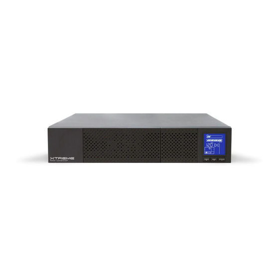
IEC C20 to L6-20R » IEC C20 to 6-20R » IEC C14 to L6-15R See the Specification section of this manual for additional model information. P90g front view P90g-1500 rear view P90g-3000 rear view Xtreme Power Conversion Corporation Page 8... - Page 9 P90g User’s Manual Uninterruptible Power Supply Front Panel Selector buttons Rack Display Tower Display Xtreme Power Conversion Corporation Page 9...
-
Page 10: Communication Connections
The UPS will have to be manually restarted in order to regain power to the outlets on the UPS. Keep Pin 1 and Pin 2 closed for UPS normal operation. To activate EPO function, open the wire between Pin 1 and Pin 2. Xtreme Power Conversion Corporation Page 10... -
Page 11: Hardware Installation Guide
• Space and ventilation requirements must be met. Ensure there is 100mm behind and 50mm on the sides of the UPS for proper ventilation. • Ensure that the front of the UPS remains clear for user operation. Xtreme Power Conversion Corporation Page 11... -
Page 12: Ups Installation
For safety considerations, the UPS is shipped from the factory with battery wire disconnected. Before installing the UPS, please follow these steps to connect of the battery wires. Connecting the batteries Step 1 Remove the front panel Step 2 Connect the battery wires Xtreme Power Conversion Corporation Page 12... - Page 13 Slide the UPS into the rack and secure using hardware provided Rack-mount Installation (using 4-post rail kit) Package contents • Right and left rail sliders, 1 each • (2) M6 nuts • (12) M6 screws Xtreme Power Conversion Corporation Page 13...
- Page 14 Uninterruptible Power Supply Step 1 Use 4 screws to mount right and left rail sliders in front of rack. Step 2 Use 4 screws to mount right and left rail sliders in back of rack. Xtreme Power Conversion Corporation Page 14...
- Page 15 Place the nuts in the proper location in the rack based upon height of UPS. Step 4 Carefully place the UPS on the rail support. Step 5 Fix the UPS in position with screws. Xtreme Power Conversion Corporation Page 15...
- Page 16 Step 6 Rail kit installation is now complete. Tower Installation Step 1 Inter-connect the tower brackets that shipped in the box with the UPS Step 2 Carefully lower the UPS into the brackets as shown Xtreme Power Conversion Corporation Page 16...
-
Page 17: Starting The Ups
CD: 1. Got to the website http://www.power-software-download.com 2. Click ViewPower software icon and then choose your required Operating System to download the soft- Xtreme Power Conversion Corporation Page 17... -
Page 18: Battery Replacement
NOTE: Please beware that once the battery tray is disconnected from the UPS, the equipment connected to the output of the UPS is not protected from power outages. Step 1 Remove the front panel Step 2 Disconnect the battery tray connector from the UPS Xtreme Power Conversion Corporation Page 18... - Page 19 Step 4 Slide the new battery tray back to the original location in the UPS and secure with the two screws to the front panel Step 5 Reconnect the battery tray connector to the UPS Xtreme Power Conversion Corporation Page 19...
-
Page 20: Operations
• Setting mode: Press and hold this button for 5 seconds to enter the UPS setting mode when UPS is off. • Down key: Press this button to display the next selection in UPS setting mode. Xtreme Power Conversion Corporation Page 20... -
Page 21: Lcd Panel
Indicates the output/input voltage, output/input frequency or battery volt- age. V: output voltage, Hz: frequency Load information Indicates the load level by 0-25%, 26-50%, 51-75%, and 76-100%. Indicates overload. Indicates the load or the UPS output is short circuited. Xtreme Power Conversion Corporation Page 21... -
Page 22: Audible Alarms
Audible Alarms Description Buzzer status Battery Mode Sounds every 4 seconds Low Battery Sounds every second Overload Sounding twice every second Fault Continuously sounds Abbreviations in LCD Display Abbreviation Display Meaning Enable Disable Escape Xtreme Power Conversion Corporation Page 22... -
Page 23: Ups Setting
Input Voltage is Out of Bypass Range UPS Setting There are two parameters to set up the UPS. Parameter 1: for program alternatives – there are 9 programs to set up. Parameter 2: for setting information display. Xtreme Power Conversion Corporation Page 23... - Page 24 BAT 60: sets output frequency to 60Hz If converter mode is enabled, you may choose the fol- lowing output frequency: CF 50: sets output frequency to 50Hz CF 60: sets output frequency to 60Hz Xtreme Power Conversion Corporation Page 24...
- Page 25 ENA: ECO mode enable DIS: ECO mode disable 05: AECO enable/disable Interface Setting ENA: Advanced ECO mode enable DIS: Advanced ECO mode disable 06: Bypass Mode enable/disable Interface Setting ENA: Bypass mode enable DIS: Bypass mode disable Xtreme Power Conversion Corporation Page 25...
- Page 26 0-999: setting the backup time limits in minutes from 0-999 for programmable outlets connected to non-crit- ical devices when operating in battery mode. 09: LCD Display Direction Setting Interface Setting RAC: the LCD display is horizontal. TOE: the LCD display is vertical. Xtreme Power Conversion Corporation Page 26...
-
Page 27: Operating Mode Description
(± 3% AECO Mode (Advanced Vo max), UPS will provide Efficiency Corrective voltage to output via static Optimizer) bypass circuit for energy sav- ing. PFC and INVERTER are off in this mode. Xtreme Power Conversion Corporation Page 27... - Page 28 The UPS is in fault mode when no output power is supplied from the UPS and Fault Mode the fault icon flashes on the LCD display, although the in- formation from the UPS can be displayed on the screen. Xtreme Power Conversion Corporation Page 28...
-
Page 29: Fault Reference Codes
Sounds every second EPO enable Sounds every second Over temperature Sounds every second Charger failure Sounds every second Battery fault Sounds every second Bypass out of range Sounds every second Bypass frequency unstable Sounds every second Xtreme Power Conversion Corporation Page 29... -
Page 30: Troubleshooting
Disconnect loads and check to see Fault code is shown as 14 and because short circuit condition oc- if output wiring or connected devic- alarm is sounding continuously. curred on the UPS output. es are in short circuit status. Xtreme Power Conversion Corporation Page 30... -
Page 31: Storage & Maintenance
Batteries may cause electric shock and have a high short-circuit current. Please remove all watches, rings and other metal personal objects before maintenance or repair, and only use tools with insulated grips and handles for maintaining or repairing. Xtreme Power Conversion Corporation Page 31... -
Page 32: Batteries
The life of batteries used in these UPS products is estimated at 3-6 years depending on level of usage. Once the battery is no longer useful and must be replaced, please contact service personnel for assistance. Xtreme Power Conversion Corporation Page 32... -
Page 33: Specifications
Software CD, horizontal brackets, tower pedestals, user manual AVAILABLE OPTIONS 5 year extended warranty, bypass distribution (XBDM), power distribution (XPDU), 4-post rail kit, 2-post shelf kit, wall mount bracket *Depending on load level **P90g-3000 capacity derates 20% at 208VAC output voltage Xtreme Power Conversion Corporation Page 33... -
Page 34: Shipping List
P90g User’s Manual Uninterruptible Power Supply Shipping List 1. ViewPower CD 2. horizontal brackets (front) 3. tower stand brackets 4. manual 5. 4ft USB cable 6. 8ft L6-20P input cable Xtreme Power Conversion Corporation Page 34... -
Page 35: Obtaining Service
RMA number marked on the outside of the boxes. 4. Return the UPS by insured, prepaid carrier to the address provided by the Technician. 5. Refer to the Warranty statements in this manual for additional details on what is covered. Xtreme Power Conversion Corporation Page 35... -
Page 36: Xtreme Power Conversion Limited Warranty
Purchaser’s sole and exclusive remedy for breach of any warranty, expressed or implied, concerning Xtreme Power Conversion equipment, and the only obligation of XPC Corporation under this warranty, shall be the repair or replacement of defective equipment, components, or parts;... -
Page 37: Xtreme Power Conversion Load Protection Policy
P90g User’s Manual Uninterruptible Power Supply Xtreme Power Conversion Load Protection Policy THIS POLICY IS NOT A WARRANTY. REFER TO THE XPC CORPORATION, INC. LIMITED WARRANTY FOR INFORMATION CONCERNING THE WARRANTY FOR YOUR XPC PRODUCT. THE LIMITATIONS AND CONDITIONS CONTAINED IN THIS POLICY DO NOT AFFECT THE TERMS OF THE XPC LIMITED WARRANTY. - Page 38 Purchaser and the name of the power utility supplier for the location of the Connected Equipment. XPC will forward to the Purchaser a Load Protection Policy claims form, which Xtreme Power Conversion Corporation Page 38...
- Page 39 No employee of XPC or any other party is authorized to make any representations beyond those made in this agreement con- cerning the Load Protection Policy. XPC Corporation 230 Yuma Street Denver, CO 80223 1.800.582.4524 Xtreme Power Conversion Corporation Page 39...
-
Page 40: Appendix A: P90-Bp36 & P90-Bp72 User Guide
• Do not plug or unplug the battery connector if UPS works in DC (discharging) mode. Product Overview and Setup NOTE: Before installation, please inspect the unit. Be sure that nothing inside the package is damaged. Please keep the original package in a safe place for future use. Xtreme Power Conversion Corporation Page 40... - Page 41 4. Do not place the unit in a dusty or corrosive environment or near any flammable objects. 5. This unit is not designed for outdoor use. This unit can either be rack mounted or placed vertically on the desk. Rack Installation Xtreme Power Conversion Corporation Page 41...
-
Page 42: Type Of Battery Required
NOTE: MAKE SURE THAT THE BATTERY BOX IS DISCONNECTED FROM THE UPS BEFORE PERFORMING THE FOLLOW- ING SEQUENCE OF OPERATIONS. P90-BP36 Step 1 : Open the package and place the battery box on a horizontal plane. Xtreme Power Conversion Corporation Page 42... - Page 43 Step 4: Remove the metal top cover of the battery box by unscrewing 6 screws present on the two sides (3 on the right side and 3 on the left side), 3 screws on the top and 4 screws on the back side. Xtreme Power Conversion Corporation Page 43...
- Page 44 Note: To install the second string of batteries, repeat the same procedure on the right side of battery box. Step 7: Connect all batteries following the wiring diagram shown in next chapter. Xtreme Power Conversion Corporation Page 44...
- Page 45 Step 4: Remove the metal top cover of the battery box by unscrewing 8 screws present on the two sides (4 on the right side and 4 on the left side), 3 screws on the top and 4 screws on the back side. Xtreme Power Conversion Corporation Page 45...
- Page 46 Note: To install the second string of batteries, repeat the same procedure on the right side of battery box. Step 7: Connect all batteries following the wiring diagram shown in next chapter. Xtreme Power Conversion Corporation Page 46...
-
Page 47: Wiring Diagram
Step 9: Put the metal top cover back on the unit. Close the front fixing plate and the two parts of the front panel and secure it with screws. Step 10: Connect the battery box to the UPS. Wiring Diagram P90-BP36 Xtreme Power Conversion Corporation Page 47... - Page 48 Note: The cable connection from the external battery connector to PCB is already present inside the battery box. All the other cable connections should be made in accordance with the above wiring diagram. P90-BP72 1st battery bench Batt Link PCBA + Batt Link PCBA - BLACK Breaker BLACK 2nd battery bench Xtreme Power Conversion Corporation Page 48...
-
Page 49: Storage & Maintenance
Before storing, charge the unit 4 hours. Store the unit covered and upright in a cool, dry location. During storage, recharge the battery in accordance with the following table: Storage Temperature Recharge Frequency Charging Duration -25°C - 40°C Every 3 months 1-2 hours 40°C - 45°C Every 2 months 1-2 hours Xtreme Power Conversion Corporation Page 49...
Need help?
Do you have a question about the P90g Series and is the answer not in the manual?
Questions and answers