IBM 6400 Setup Manual
Line matrix printer
cabiner and pedestal models
Hide thumbs
Also See for 6400:
- Programmer's reference manual (450 pages) ,
- Maintenance manual (428 pages) ,
- Maintenance information manual (422 pages)

Related Manuals for IBM 6400


Summary of Contents for IBM 6400
-
Page 1: Setup Guide
6400 Line Matrix Printers Setup Guide Cabinet and Pedestal Models Form Number S544–5640–00 ©Copyright IBM Corp., 1998... - Page 3 6400 Line Matrix Printers S544–5640–00 Setup Guide Cabinet and Pedestal Models...
- Page 4 Requests for IBM publications should be made to your IBM representative or to the IBM branch office serving your locality. Publications are not stocked at the address given below.
-
Page 5: Table Of Contents
1–3 The IBM 6400 Printer ......... . . - Page 6 Removing Shipping Restraints (Pedestal Models) ..... 2–21 Remove the Protective Film ........2–22 Remove the Hammer Bank Protective Foam .
- Page 7 Loading Custom Sets or Factory Default Values ..... . 3–23 Changing the Power On Configuration ......3–25 Configuration Menus Overview...
- Page 8 Active Print Language ........4–22 Printer Emulation .
- Page 9 Format Control ..........4–36 Maximum Printable Width .
- Page 10 Data Bit 8 ..........4–48 Data Polarity .
- Page 11 Proprinter III XL Emulation Menu ....... . . 4–61 Print Language .
- Page 12 Elong./Alt. Font ..........4–75 High Speed Print Mode .
- Page 13 Overview ........... . . 5–2 RS–232 and RS–422 Serial Interfaces .
- Page 14 Running a Job ..........7–5 New Ribbon .
-
Page 15: Energy Star
References in this publication to IBM products, programs, or services do not imply that IBM intends to make these available in all countries in which IBM operates. Any reference to an IBM licensed product, program, or service is not intended to state or imply that only IBM’s product, program, or service may be used. -
Page 16: Communication Notices
Properly shielded and grounded cables and connectors must be used in order to meet FCC emission limits. IBM is not responsible for any radio or television interference caused by using other than recommended cables and connectors or by unauthorized changes or modifications to this equipment. - Page 17 TV communication and to other electrical or electronic equipment. Such cables and connectors are available from IBM authorized dealers. IBM cannot be responsible for any interference caused by using other than recommended cables and connectors.
-
Page 18: Electrical Safety
Trademarks and Service Marks The following terms, denoted by an asterisk (*) in this publication, are trademarks of the IBM Corporation in the United States or other countries or both. Application System 1400... -
Page 19: Safety Notices
Safety Notices DANGER: <1> Before powering on the printer ensure the printer is plugged into an appropriate power source. Refer to Chapter 2 of the Setup Guide for information on the proper source. <2> Switch off the printer power and unplug the printer power cord before cleaning the printer. -
Page 21: Introduction
1–3 The IBM 6400 Printer ......... . . -
Page 22: About This Setup Guide
Danger and Caution notices are numbered. These numbers enable you to find translated versions of these notices in the IBM 6400 Line Matrix Printer Safety Notices booklet. Descriptions for each type of notice follow: DANGER: <#>... -
Page 23: Format Conventions
IBM 6400 Line Matrix Printer Maintenance Information Manual (S246–0117) — Explains how to maintain and repair the 6400 line matrix printer at the field service level of maintenance. This manual covers alignments and adjustments, preventive and corrective maintenance, troubleshooting, and basic principles of operation. - Page 24 (S544–5642) — Describes how to install and use this feature to support coax/twinax attachment to host systems. IBM 6400 Code V User’s Manual (S544–5638) — Provides information used with the optional Code V** Printronix** emulation enhancement feature. The Code V Printronix emulation allows you to create and store forms;...
-
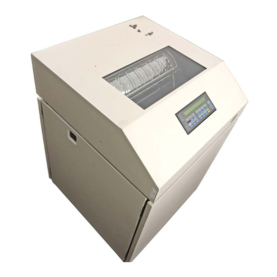
Page 25: The Ibm 6400 Printer
The IBM 6400 Printer The IBM 6400 printers offer software versatility and the latest refinements in line matrix printing technology. Most line printers have specialized architectures that enable them to emulate, or behave like another printer. Your IBM printer, however, introduces an open architecture in which numerous emulations may be selected from the operator panel. - Page 26 Cabinet Models Cabinet Models with Power Paper Stacker Pedestal Models Figure 1–1. The IBM 6400 Line Matrix Printer 1–6 6400 Line Matrix Printers Setup Guide, Cabinet and Pedestal Models...
-
Page 27: Standard Capabilities
Supports similar features across the entire product line to allow maximum flexibility in matching the printer to the requirements ** compliant NERGY The following sections summarize the standard capabilities of the IBM 6400 printer. Host Computer Interfaces The following host computer interface choices are available: RS–232 Serial... - Page 28 This emulation appears as “P-Series XQ” on the operator panel. Printronix Serial Matrix Printer Emulation This printer emulation is very similar to the code systems used by an IBM Graphics Printer, but incorporates several systems into one emulation. This emulation enables a line matrix printer to print files coded for a serial matrix printer, and is sometimes referred to as the Serial Matrix emulation.
-
Page 29: Output Control
Graphics and Vertical Formatting Several graphics and vertical formatting features are available: Three built-in graphics generators: 1) IBM Proprinter III XL bit-image graphics 2) Epson FX dot graphics mode 3) Printronix P-Series Plot Programmable electronic vertical formatting provides rapid vertical paper movement to specified lines for printing repetitive and continuous forms. -
Page 30: Built-In Diagnostic Tools
IBM 3262 Models 3 and 13, IBM 4234 Models 1, 2, and 9, and IBM 5224 Models 1 and 2. This feature can be used with the Intelligent Printer Data Stream (IPDS) feature which is described below. - Page 31 Magnum emulation and those applications that use the Printronix Code V Graphics Language. The Printronix Code V Graphics Language is often referred to as VGL. This feature can co-exist with the IBM Intelligent Printer Data Stream feature, and/or with either coax/twinax feature, or can be used on the ASCII models.
-
Page 32: Protocols And Emulations
When the printer executes the character and control codes of a particular printer protocol, it is “emulating” that printer. If the printer uses the Proprinter III XL protocol, for example, it is emulating an IBM Proprinter III XL printer. If the printer is using the Epson FX printer protocol, for example, we can also say it is in Epson FX emulation mode. -
Page 33: Overview
Setting Up the Printer Chapter Contents Installation, Attachment and Configuration Overview ....2–3 Before You Begin ..........2–5 Select a Site . - Page 34 ..........2–55 2–2 6400 Line Matrix Printers Setup Guide, Cabinet and Pedestal Models...
-
Page 35: Setting Up The Printer
5. Attach the printer to the host system and configure the host system to work with the printer. a. For ASCII attachments, follow the instructions in the 6400 ASCII Programmer’s Reference Manual. Chapter 2. Setting Up the Printer... - Page 36 If you want to order a manual to learn more about these features, see the “Related Documents” section that begins on page 1–3. 2–4 6400 Line Matrix Printers Setup Guide, Cabinet and Pedestal Models...
-
Page 37: Before You Begin
Before You Begin Read this chapter carefully before installing and operating the IBM 6400 printer. The printer is easy to install, but for your safety and to protect valuable equipment, perform all the procedures in this chapter in the order presented. -
Page 38: Select A Site
Ethernet 10Base–T 100 meters (328 feet) Ethernet 10Base–2 185 meters (607 feet) NOTE: For more reliable data transfers, a maximum of six feet is recommended for parallel cable length. 2–6 6400 Line Matrix Printers Setup Guide, Cabinet and Pedestal Models... - Page 39 Printer Cover Cabinet Rear Door Cabinet Model 57.5 in. (146.1 cm) 41.0 in. (104 cm) 27.0 in. (68.6 cm) 29.0 in. (73.7 cm) 83.0 in. (210.8 cm) 27.0 in. 27.0 in. 25 in. 27.0 in. (68.6 cm) (68.6 cm) (68.6 cm) (63.5 cm.) 10.5 in.
-
Page 40: Printer Component Locations
Lower Paper Guide Paper Supports Horizontal Adjustment Tractor Lock Knob Tractor Lock Ribbon Loading Path Diagram Vertical Position Knob Forms Thickness Lever Forms Thickness Pointer Figure 2–2. Cabinet Model Component Locations 2–8 6400 Line Matrix Printers Setup Guide, Cabinet and Pedestal Models... - Page 41 Ribbon Spool Tractor Splined Shaft Tractor Hub Latch Platen Ribbon Hub Base Casting Shuttle Cover Assembly Forms Thickness Lever Ribbon Hammer Bank Guide (2) (beneath shuttle cover assembly) Ribbon Mask Figure 2–2. Cabinet Model Component Locations (Cont.) Chapter 2. Setting Up the Printer 2–9...
- Page 42 Tractor Door Right Tractor Left Tractor Horizontal Adjustment Knob Tractor Lock Operator Panel Forms Thickness Lever Base Ribbon Ribbon Mask Path Paper Scale Diagram Figure 2–3. Pedestal Model Component Locations 2–10 6400 Line Matrix Printers Setup Guide, Cabinet and Pedestal Models...
- Page 43 Ribbon Spool Printer Cover Adjustable Paper Guide Shuttle Adjustable Cover Assembly Hinge Splined Shaft Forms Ribbon Hub Thickness Lever Ribbon Guide (1 of 2) Hub Latch Figure 2–3. Pedestal Model Component Locations (Cont.) Chapter 2. Setting Up the Printer 2–11...
-
Page 44: Removing Shipping Restraints (Cabinet Models)
Save the cardboard packing and protective foam with the other packing materials. To avoid shipping damage, reinstall the shipping restraints whenever the printer is moved or shipped. To reinstall the shipping restraints, simply reverse the steps in this section. 2–12 6400 Line Matrix Printers Setup Guide, Cabinet and Pedestal Models... -
Page 45: Remove The Cardboard Packing And Envelope
Remove the Cardboard Packing and Envelope Cardboard Packing Cardboard Packing Figure 2–4. Removing the Cardboard Packing and Envelope 1. Raise the printer cover. 2. Remove the cardboard packing. 3. Open the tractor doors. Push the tractor locks down. Slide the tractors outward as far as they will go. -
Page 46: Remove The Hammer Bank Protective Foam
1. Slide the paper supports outward as far as they will go. Lift the hammer bank protective foam and remove it from between the ribbon mask and the platen. 2. Rotate the forms thickness lever downward to position “A.” 2–14 6400 Line Matrix Printers Setup Guide, Cabinet and Pedestal Models... -
Page 47: Remove The Platen Protective Foam
Remove the Platen Protective Foam Platen Protective Foam Support Shaft Forms Thickness Lever Figure 2–6. Removing the Platen Protective Foam 1. Rotate the platen protective foam toward the front of the printer and out from under the support shaft. Remove the platen protective foam. Chapter 2. - Page 48 2. Remove the foam strips and the tape securing the foam strips. 3. Carefully peel off the tape and lift the protective film off the operator panel message display. 2–16 6400 Line Matrix Printers Setup Guide, Cabinet and Pedestal Models...
-
Page 49: Release The Paper Chains
Release the Paper Chains Tie Wrap Paper Chains Tie Wrap Plastic Bags Figure 2–8. Releasing the Paper Chains 1. Open the rear cabinet door. 2. Cut the tie wraps and release the paper chains from the bags at the top rear of the printer frame. -
Page 50: Removing Tags
1. Remove the tie wrap that is attached to the paper fence. It is marked with a large, red tag. If you have a Power Paper Stacker, skip this procedure. 2. Close the rear cabinet door. 2–18 6400 Line Matrix Printers Setup Guide, Cabinet and Pedestal Models... -
Page 51: Remove The Power Stacker Shipping Restraints
Remove the Power Stacker Shipping Restraints 3. This section only applies to printers with the power stacker installed. The power stacker can be factory or field installed. 4. The power stacker is a vertically movable paper guide which directs the paper from the printer to the paper stack. - Page 52 2. Remove tie wraps. 3. Raise the paper guide to its highest position by hand. 4. Remove bubble wrap. 5. Verify that both fences are in the down position. 2–20 6400 Line Matrix Printers Setup Guide, Cabinet and Pedestal Models...
-
Page 53: Removing Shipping Restraints (Pedestal Models)
Removing Shipping Restraints (Pedestal Models) Protective films and foam blocks protect printer mechanisms from possible damage during shipment. You must remove these shipping restraints before you operate the printer. Save the foam blocks with the other packing materials. To avoid shipping damage, reinstall the shipping restraints whenever the printer is moved or shipped. -
Page 54: Remove The Protective Film
(in the fully open position). 4. Remove the envelope that contains the sample configuration printout. Store this envelope in a safe place so that you can refer to the configuration printout. 2–22 6400 Line Matrix Printers Setup Guide, Cabinet and Pedestal Models... -
Page 55: Remove The Hammer Bank Protective Foam
Remove the Hammer Bank Protective Foam Hammer Bank Protective Foam Paper Support Tractor Door Tractor Lock Figure 2–12. Removing the Hammer Bank Protective Foam 1. Slide the paper supports outward as far as they will go. 2. Lift the hammer bank protective foam and remove it from between the ribbon mask and the platen. -
Page 56: Remove The Platen Protective Foam
1. Rotate the forms thickness lever downward (to position “A”). See Figure 2–13. 2. Rotate the platen protective foam toward the front of the printer and out from under the support shaft. Remove the platen protective foam. 2–24 6400 Line Matrix Printers Setup Guide, Cabinet and Pedestal Models... -
Page 57: Attach The Input Paper Shelf And Output Basket
Attach the Input Paper Shelf and Output Basket Output Basket Paper Supports Optional Input Paper Shelf Figure 2–14. Attaching the Input Paper Shelf and Output Basket 1. Slide the two paper supports toward the center of the support shaft. Position them so that they divide the space between the tractors into three approximately equal segments. -
Page 58: Connect The Interface And Power Cables (Cabinet Models)
4. Thread the power cable connector up through the notch in the lower right back corner of the cabinet (see Figure 2–15). Plug the power cord into the printer AC power connector, then into the AC power outlet. 2–26 6400 Line Matrix Printers Setup Guide, Cabinet and Pedestal Models... - Page 59 Power Switch Coax Interface Connector PC Parallel Interface Connector Twinax Interface Connector Connector Cover Host Interface Cable RS–232/ RS–422 Serial Connector AC Power Connector Cable–Routing Notches Notes: AC Power Cable The Dataproducts adapter feature attaches to the PC Parallel interface connector. Twinax, Coax, and Ethernet Interfaces appear only if these features are installed.
- Page 60 1. Check the product description label to verify that the voltage source at the printer site conforms to the requirements specified on page 2–6. Figure 2–17. Power Switch 2. Make sure the printer power switch is set to OFF. 2–28 6400 Line Matrix Printers Setup Guide, Cabinet and Pedestal Models...
- Page 61 Parallel Connector Serial Connector Figure 2–18. Removing the I/O Cover 3. Open the rear cabinet door, and remove the cover from the I/O connector you have selected. Figure 2–19. Cable Routing Notch 4. Locate the notch in the lower left corner of the back of the cabinet.
- Page 62 Attach the cable connector to the printer interface connector previously selected in step 3 of this section. Secure the cable to the printer using the two cable standoffs. See Figure 2–15. Figure 2–21. Routing the Power Cord 2–30 6400 Line Matrix Printers Setup Guide, Cabinet and Pedestal Models...
- Page 63 7. Guide the power cord up through the hole in the lower right back corner of the cabinet. Thread the power cord inside the bracket where the gas spring is attached. Figure 2–22. Attaching the Power Cord 8. Plug the power cord into the printer AC power connector, then into the AC power outlet.
-
Page 64: Connect The Interface And Power Cables (Pedestal Models)
Attach the cable connector to the printer interface connector. 4. Plug the power cord into the printer AC power connector, then into the AC power outlet (see Figure 2–23). 2–32 6400 Line Matrix Printers Setup Guide, Cabinet and Pedestal Models... - Page 65 PC Parallel Interface Connector Coax Interface Connector Twinax Interface Connector RS-232/RS-422 Serial Connector Network 10Base2 Network 10BaseT Power Switch NOTES: The Dataproducts adapter feature attaches to the PC Parallel interface connector. Twinax and Coax Interfaces appear only if these features are installed. The Multi–Platform Interface Coax/Twinax feature is not shown in this illustration.
- Page 66 Figure 2–24. Removing the I/O Cover 5. Remove the cover from the I/O connector you have selected. Figure 2–25. Attaching the Cable Connector 6. Attach the cable connector to the printer interface connector. 2–34 6400 Line Matrix Printers Setup Guide, Cabinet and Pedestal Models...
- Page 67 Power Cord AC Power Connector Figure 2–26. Attaching the Power Cord 7. Plug the power cord into the printer AC power connector, then into the AC power outlet. Chapter 2. Setting Up the Printer 2–35...
- Page 68 Network 10 Base 2 Network 10 Base T Coax / Twinax 90 BNC connector required for Coax connection with the Power Stacker. Figure 2–28. Optional Interfaces for Auxiliary I/O 2–36 6400 Line Matrix Printers Setup Guide, Cabinet and Pedestal Models...
-
Page 69: Attach The Operator Panel Overlay Label
Attach the Operator Panel Overlay Label Attach the operator panel overlay label by adhering it to your operator panel. See Figure 2–29. Power READY Ready Processing Micro Line Form Start Cancel Menu Scroll Enter Feed Feed Micro View Set Top Stop Eject/ Printer Con–... -
Page 70: Install The Ribbon
Install the Ribbon 1. Refer to the ribbon path diagram molded onto the shuttle cover for the following steps. See Figure 2–2. Figure 2–30. Opening the Printer Cover 2–38 6400 Line Matrix Printers Setup Guide, Cabinet and Pedestal Models... - Page 71 2. Open the printer cover. See Figure 2–30. 3. On pedestal models, swing the operator panel out of the way. The operator panel can be pulled toward you to provide clearance. See Figure 2–30. Tractor Door Forms Thickness Lever Figure 2–31. Forms Thickness Lever 4.
- Page 72 7. With the ribbon supply to the outside, squeeze the right hub latch and place the full spool on the right ribbon hub. Press the spool down until the hub latch snaps into place. See Figure 2–32. 2–40 6400 Line Matrix Printers Setup Guide, Cabinet and Pedestal Models...
- Page 73 Paper Ribbon Mask Hammer Bank Cover Platen Ribbon Front of Printer Hammer Figure 2–33. Ribbon Path 8. Referring to Figure 2–33 and the ribbon path diagram on the shuttle cover, thread the ribbon as follows: Starting from the right ribbon spool, thread the ribbon around the right ribbon guide, under the right tractor door, between the hammer bank cover and ribbon mask, and along the ribbon path to the left ribbon guide.
- Page 74 11. Continue with the next procedure to load paper in the printer. Cabinet Models Left Ribbon Hub Left Ribbon Hub NOTE: Raise the Operator Panel when replacing ribbon on Pedestal models. Pedestal Models Figure 2–34. Left Ribbon Hub 2–42 6400 Line Matrix Printers Setup Guide, Cabinet and Pedestal Models...
-
Page 75: Load The Paper
Load the Paper Figure 2–35. Opening the Printer Cover 1. Open the printer cover. See Figure 2–35. Tractor Door Forms Thickness Lever Figure 2–36. Forms Thickness Lever 2. Raise the forms thickness lever as far as it will go. See Figure 2–36. 3. - Page 76 Ensure that the paper pulls freely from the box. Paper Slot is 8 inches below printer base Paper Slot Figure 2–38. Feeding the Paper 2–44 6400 Line Matrix Printers Setup Guide, Cabinet and Pedestal Models...
- Page 77 5. Feed the paper up through the paper slot. On pedestal models, be sure the paper feeds between the two wire guides. Hold the paper in place with one hand (to prevent it from slipping down through the paper slot) while pulling it through from above with your other hand.
- Page 78 To avoid damage to the printer caused by printing on the platen, always align the edge of the left tractor door with the number “1” on the paper scale. 2–46 6400 Line Matrix Printers Setup Guide, Cabinet and Pedestal Models...
- Page 79 Vertical Position Knob Thin Paper Medium Paper Thick Paper NOTE: Thin Paper = single sheet Medium Paper = two–part form Thick Paper = six–part form Figure 2–42. The Forms Thickness Scale 9. Turn the vertical position knob to feed the paper up into the paper guide assembly.
-
Page 80: Power Paper Stacker Option
Paper Throat Pinch Rollers Rear Operator Panel Motor Bracket Paper Length Indicator Wire Paper Tent (Optional) Bearing Bracket Paddle Shaft Alignment Rod (2) Figure 2–43. Power Paper Stacker Component Locations 2–48 6400 Line Matrix Printers Setup Guide, Cabinet and Pedestal Models... -
Page 81: Setting Up The Power Paper Stacker
Setting Up the Power Paper Stacker 1. Turn the printer on. Paper Advance Stacker Up Stacker Down Figure 2–44. Rear Operator Panel 2. Using the rear operator panel, press ONLINE to take the printer offline. Press STACKER UP button and wait for the stacker to reach the top of its travel. - Page 82 The stacker frame returns to its proper position for printing. 6. Check to ensure paper is still centered between paper guides. 7. Close the rear cabinet door. 2–50 6400 Line Matrix Printers Setup Guide, Cabinet and Pedestal Models...
-
Page 83: Checking The Paper Feed
Checking the Paper Feed Paper Guide Assembly Figure 2–46. Checking the Paper Feed (Cabinet Models) 1. Cabinet models: Check that the paper feeds correctly. Press the Form Feed key several times to ensure that the paper feeds properly beyond the tractors and over the paper guide assembly. - Page 84 3. Cabinet models: Close the front and rear cabinet doors, if the length of the form allows. 4. Cabinet and pedestal models: Continue with the next procedure to set the top-of-form. 2–52 6400 Line Matrix Printers Setup Guide, Cabinet and Pedestal Models...
-
Page 85: Set The Top-Of-Form
Set the Top-of-Form Forms Thickness Lever Figure 2–48. Raising the Forms Thickness Lever 1. Raise the forms thickness lever as far as it will go. The “CLOSE PLATEN” message will appear on the operator panel. Press any key on the operator panel to silence the alarm. See Figure 2–48. Left Tractor Door TOF Indicator Paper Perforation... - Page 86 5. Press Set Top of Form. The paper moves downward to the top-of-form print position. 6. Continue with the next procedure to test the printer. 2–54 6400 Line Matrix Printers Setup Guide, Cabinet and Pedestal Models...
-
Page 87: Test The Printer
On the configuration printout, examine the print quality of the characters. They should be fully formed and of uniform density. If text characters do not appear correctly formed or if the test does not run, contact your IBM service representative. - Page 88 2–56 6400 Line Matrix Printers Setup Guide, Cabinet and Pedestal Models...
-
Page 89: Configuring The Printer
Configuring the Printer Chapter Contents Overview ........... . . 3–2 The Configurations . -
Page 90: Overview
This chapter explains how to use the operator panel to change individual parameters and save them as a custom configuration. Operator panel keys are described in the 6400 Operator’s Guide. Your programmer’s reference manuals provide information about control codes. -
Page 91: Active Versus Saved Configurations
Active versus Saved Configurations When you change a parameter value, it is active as long as the printer is on or until it is changed again. This is true whether you use the operator panel or send a control code from the host. Parameter values defined by control codes override the active operator panel parameters when the printer is using any of the parallel or serial interfaces. -
Page 92: The Configuration Main Menu
Each feature is shipped with a document that describes the feature in detail. For more information about these documents, see the “Related Documents” section that begins on page 1–3. 3–4 6400 Line Matrix Printers Setup Guide, Cabinet and Pedestal Models... - Page 93 One Char Enquiry Serial Hotport Notes: The Twinax and Coax interface menus only appear in the menus if the IBM Coax/Twinax feature is installed. If the Multi–Platform Interface Coax/Twinax feature To view options, press: is installed the Twinax and Coax Interface menus are not displayed because the Multi–Platform Interface feature does not use these menus.
-
Page 94: Using The Operator Panel
This chapter provides numerous examples of how to use the operator panel keys and indicator message display to configure the printer. The operator panel key functions are described in detail in your 6400 Operator’s Guide. 3–6 6400 Line Matrix Printers Setup Guide, Cabinet and Pedestal Models... -
Page 95: Program Mode
Program Mode The printer is in Program mode whenever the configuration menus and option values are displayed on the operator panel message display. Program mode is either locked or unlocked. In order to select new configuration values, you must unlock Program mode. In order to prevent accidental changing of the configuration settings, you may lock Program mode. -
Page 96: Printing The Current Configuration
The second method for printing the current configuration, as well as several other configurations, is to use the Print Custom Set Values menu option, shown on the following page. 3–8 6400 Line Matrix Printers Setup Guide, Cabinet and Pedestal Models... - Page 97 CONFIGURATION MANAGEMENT Protect Print Custom Recall Save Current Delete Change Custom Sets Set Values Custom Set Values Custom Set Power On Set Current Custom Set* Factory Default Power On Custom Set * = Factory Default All Custom Sets Custom Set 1 Custom Set 2 Custom Set 3 Custom Set 4...
-
Page 98: Factory Default Configuration Values
120 Dots per inch Eject/Restore Standard PTR Setup Option Setup Parse Disable Setup SFCC File System Overwrite Files Enable View File List Version 69 Bytes Optimize&Reboot Print File List 3–10 6400 Line Matrix Printers Setup Guide, Cabinet and Pedestal Models... - Page 99 CONFIGURATION MANAGEMENT Recall Custom Set Factory Default Save Current Values Custom Set 1 Delete Custom Set Custom Set 1 Change Power On Set Factory Default Protect Custom Sets Disable Print Custom Set Values Current Custom Set (10) ETHERNET PARAMETERS Buffer Size in Kilobytes IPO Address 192.168.022.013 Gateway Address...
- Page 100 Enable TOF Action at Prime Signal Form Feed at Reset Buffer Size in Kilobytes Dataproducts Data Bit 8 Enable PI Ignored Enable Data Polarity Standard Data Request Polarity Standard 3–12 6400 Line Matrix Printers Setup Guide, Cabinet and Pedestal Models...
- Page 101 Strobe Polarity Standard IEEE 1284 Parallel Hotport Trickle Time 1/4 Sec Timeout 10 Sec. Report Status Disable SERIAL INTERFACE Interface Type RS 232 Data Protocol XON/XOFF Baud Rate 9600 Baud Data Bits Stop Bits Parity None Data Terminal Ready READY and Buffer Not Full Request to Send True Buffer Size in Kilobytes...
- Page 102 Alternate Character Set PC Character Set 1 Define CR Code CR = CR Auto LF Enable Define LF Code LF = LF FF Valid at TOF Enable 20 CPI Condensed Enable 3–14 6400 Line Matrix Printers Setup Guide, Cabinet and Pedestal Models...
- Page 103 Enable Define LF Code LF = LF Printer Select Disable 20 CPI Condensed Enable P–Series Emulation Character Sets IBM PC Print Language IBM PC Select Subset Primary ASCII (USA) Select Subset Extended 0437 PC Character Set Multinational ASCII (USA) ECMA Latin 1...
- Page 104 XXX.X Hours Printing Time: XX Hours Print Strokes XXXXXXX 11 Inch Pages XXXX RibbonMinder New Ribbon Ribbon Action Disable Ribbon Size 100 Yards Ribbon Adjust Fault Action New Ribbon 3–16 6400 Line Matrix Printers Setup Guide, Cabinet and Pedestal Models...
- Page 105 Notes: Twinax and Coax Interface only appear in the menus if these features are installed. Menus are shown in Chapter 4. If the Multi–Platform Interface Coax/Twinax feature is installed the Twinax and Coax Interface menus are not displayed because the Multi–Platform Interface Coax/Twinax feature does not use these menus.
-
Page 106: Changing Parameters
Unlocks the Operator Menu, OPERATOR MENU UNLOCKED which allows you to make Scroll Scroll configuration changes. Displays the first OPERATOR MENU Menu Configuration Main Menu PRINTER CONTROL option, PRINTER CONTROL. 3–18 6400 Line Matrix Printers Setup Guide, Cabinet and Pedestal Models... - Page 107 Step Result Notes Moves into the PRINTER PRINTER CONTROL Enter CONTROL menu. INTERFACE SELECTION Moves to the PRINT PRINTER CONTROL Scroll UNTIL DIRECTION parameter. PRINT DIRECTION Moves into the PRINT PRINT DIRECTION Enter DIRECTION menu. The BIDIRECTIONAL* asterisk (*) shows that this is the active value.
-
Page 108: Saving Your Configuration In A Custom Set
NOTE: To avoid overwriting an existing custom set, the Protect Custom Sets parameter must be set to ENABLE. See page 4–19 for details. 3–20 6400 Line Matrix Printers Setup Guide, Cabinet and Pedestal Models... - Page 109 Step Result Notes Press: Places the printer in NOT READY Stop NOT READY mode. Unlocks the Operator OPERATOR MENU Scroll Scroll Menu, which allows UNLOCKED you to save configuration changes. Displays the OPERATOR MENU Menu PRINTER CONTROL PRINTER CONTROL option on the Configuration Main Menu.
- Page 110 Operator Menu. Places the printer in READY Start READY mode, prepared for normal operation. It is recommended you make a printout of your current configuration, as described on page 3–8. 3–22 6400 Line Matrix Printers Setup Guide, Cabinet and Pedestal Models...
-
Page 111: Loading Custom Sets Or Factory Default Values
Loading Custom Sets or Factory Default Values CONFIGURATION MANAGEMENT Change Recall Delete Protect Print Custom Save Current Power On Set Custom Set Custom Set Custom Sets Set Values Values Factory Default* Custom Set 1 Custom Set 2 Custom Set 3 Custom Set 4 Custom/Preloaded Set 5 Custom/Preloaded Set 6... - Page 112 NOT READY mode. Locks Program mode OPERATOR MENU Scroll Scroll LOCKED and the Operator Menu. Places the printer in READY Start READY mode, with the Factory Default values loaded. 3–24 6400 Line Matrix Printers Setup Guide, Cabinet and Pedestal Models...
-
Page 113: Changing The Power On Configuration
Changing the Power On Configuration CONFIGURATION MANAGEMENT Delete Protect Recall Save Current Change Power Print Custom Custom Set Custom Sets Custom Set Values On Set Set Values Factory Default* Custom Set 1 Custom Set 2 Custom Set 3 Custom Set 4 Custom/Preloaded Set 5 Custom/Preloaded Set 6 Custom/Preloaded Set 7... - Page 114 CHANGE POWER ON SET Enter POWER ON SET FACTORY DEFAULT option, FACTORY DEFAULT. Displays CHANGE POWER ON SET Scroll CUSTOM SET 1 as the CUSTOM SET 1 POWER ON SET option value. 3–26 6400 Line Matrix Printers Setup Guide, Cabinet and Pedestal Models...
- Page 115 Step Result Notes An * appears after the CHANGE POWER ON SET Enter change is complete. CUSTOM SET 1* Returns the printer to NOT READY Stop NOT READY mode. Locks Program mode OPERATOR MENU Scroll Scroll LOCKED and the Operator Menu. Places the printer in READY Start...
- Page 116 3–28 6400 Line Matrix Printers Setup Guide, Cabinet and Pedestal Models...
-
Page 117: Configuration Menus
Configuration Menus Chapter Contents Overview ........... . . 4–7 The Configuration Main Menu . - Page 118 ..........4–36 4–2 6400 Line Matrix Printers Setup Guide, Cabinet and Pedestal Models...
- Page 119 Maximum Printable Width ........4–36 C/T Hotport .
- Page 120 ........4–62 4–4 6400 Line Matrix Printers Setup Guide, Cabinet and Pedestal Models...
- Page 121 Define CR Code ..........4–62 Auto LF .
- Page 122 ..........4–94 4–6 6400 Line Matrix Printers Setup Guide, Cabinet and Pedestal Models...
-
Page 123: Overview
Chapter 4, “Configuration Menus,” because many customers order this feature at the factory. The Coax/Twinax interface for the Multi–Platform Interface Coax/Twinax feature is documented in the 6400 Coax/Twinax Multi–Platform Interface Option Installation and Operation Guide. The menus for the IPDS, Code V, and IGP are documented in Appendix E: Code V, IGP, and IPDS Menus. - Page 124 The Scroll± key moves backward through the options at a particular menu level. These keys are summarized in a legend box at the lower right corner of each configuration menu diagram. 4–8 6400 Line Matrix Printers Setup Guide, Cabinet and Pedestal Models...
-
Page 125: The Configuration Main Menu
Serial Hotport Ribbon Action Ribbon Size The Twinax and Coax interface menus only appear in the menus if the IBM Coax/Twinax feature is installed. If the Multi–Platform Interface Coax/Twinax feature Ribbon Adjust is installed the Twinax and Coax Interface menus are not displayed because the Fault Action Multi–Platform Interface feature does not use these menus. -
Page 126: Printer Control Menu
Either the Ethernet Interface menu or the Parallel Interface menu = Factory Default will be displayed. They can not both be displayed at the same time. Figure 4–2. Printer Control Menu 4–10 6400 Line Matrix Printers Setup Guide, Cabinet and Pedestal Models... -
Page 127: Interface Selection
Interface Selection INTERFACE SELECTION enables or disables physical interfaces for attachment switching. If an interface is disabled, it is set offline and any data received will be ignored. When coax or twinax is selected, a POR status is sent to the host. Selecting Autoswitching provides automatic interface switching among parallel, serial, and either coax or twinax communication. -
Page 128: Hex Print Mode
When paper jam detection is disabled, the printer does not monitor paper motion. If a paper jam occurs, the printer ignores the condition and continues to print, possibly causing severe damage to the printer. 4–12 6400 Line Matrix Printers Setup Guide, Cabinet and Pedestal Models... -
Page 129: Forms Speed
Forms Speed FORMS SPEED affects the speed at which paper moves into the stacking area of the printer. NORMAL SPEED (the default) will slew and stack paper, such as single–sheet data processing paper, at maximum speed. SLOW SPEED will slew and stack at a slower pace. This ensures that forms, such as multiple–sheet (i.e. -
Page 130: Energy Saver Timer
TOP EXIT TEAR (pedestal models only) When STANDARD mode is selected, the Eject/Restore key operates as follows: Pressing Eject/Restore causes the paper to advance a preset distance of 22 inches. 4–14 6400 Line Matrix Printers Setup Guide, Cabinet and Pedestal Models... -
Page 131: Ptr Setup Option
Pressing Ready or pressing Eject/Restore a second time causes the paper to return to its original position. NOTE: If you are using this function to tear off forms, you might want to press Form Feed before using the Eject/Restore function. This will avoid unloading the paper as it is restored to its original position. -
Page 132: File System
This parameter determines whether or not the power paper stacker is enabled, which is the default, or disabled. This parameter is not presented if the power paper stacker is not installed. 4–16 6400 Line Matrix Printers Setup Guide, Cabinet and Pedestal Models... -
Page 133: Configuration Management Menu
Configuration Management Menu CONFIGURATION MANAGEMENT (From page 4–9) Recall Delete Change Save Current Custom Set Custom Set Power On Set Values Factory Default* Custom Set 1* Custom Set 1* Factory Default* Custom Set 1 Custom Set 2 Custom Set 2 Custom Set 1 Custom Set 2 Custom Set 3... -
Page 134: Recall Custom Set
Epson and Proprinter default values. This could be useful when the printer has the Coax/Twinax feature, but is sometimes run as an ASCII printer. Refer to the 6400 Coax/Twinax Programmer‘s Reference Manual for more information. -
Page 135: Save Current Values
Save Current Values This option allows you to save your custom sets to meet different print job requirements. This eliminates the need to change the parameter settings for each new job. The custom sets are stored in NVRAM—they will not be lost if you power off the printer. -
Page 136: Twinax Interface Menu
Enter Does not apply to IPDS. To select an option, press: The Twinax and Coax interface menus only appear in the menus if the IBM To exit the configuration menus Start To exit the configuration menus Coax/Twinax feature is installed. If the Multi–Platform Interface Coax/Twinax... - Page 137 PRINT LANGUAGE (From page 4–20) Standard Print Alternate Print Language Language 0037 English (USA/Canada)* English US* 0037 English (Netherlands) Austrian/German 0500 Swiss Bilingual Belgian 0500 Belgian New Brazilian 0273 Austrian/German Canadian French 0274 Belgian Old Danish/Norwegian 0275 Brazilian Finnish/Swedish 0260 Canadian French French 0277 Danish/Norwegian Italian...
-
Page 138: Print Language
Print Character Table PRINT CHARACTER TABLE prints out a table of the twinax interface current character set. Character sets are shown in the 6400 Coax/Twinax Programmer’s Reference Manual. Active Print Language ACTIVE PRINT LANGUAGE specifies which print language set will be the active set. -
Page 139: Printer Address
6400 Coax/Twinax Programmer’s Reference Manual. You can configure the printer to use the STANDARD CHARACTER SET so the printer contains the IBM World Trade character set, such as the Austria/Germany character set. Or, you can select EXTENDED CHARACTER SET and use the multinational character set as a base with the selected world trade character set overlaid. -
Page 140: Hex Transparent Control
Hex Transparent Control This option allows you to enable (the default) or disable additional features that are not available in standard IBM emulations. To access these features, send lead–in character text commands in the data stream. You can also use ASCII codes 80 hex through 9F hex as control codes if configured to do so. -
Page 141: Undefined Character Substitution
SGEA command, refer to the 6400 Coax/Twinax Programmer’s Reference Manual. ENABLE (the default) is the host setting for the SGEA and is used by the printer. If the SGEA command is requested to stop on graphic errors, the printer will stop when a graphic error is detected. -
Page 142: Override Host
DISABLE (the default) does not reflect distance, generated by the Code V feature, IGP feature, and Hex Transparent control code sequence, in the new position (after absolute and relative move commands are executed). 4–26 6400 Line Matrix Printers Setup Guide, Cabinet and Pedestal Models... -
Page 143: Maximum Printable Width
Maximum Printable Width MAXIMUM PRINTABLE WIDTH sets the maximum width of the printer when using a CT host interface. 13.2 INCHES (the default) 13.6 INCHES NOTE: The twinax interface menu and coax interface menu option for maximum printable width use the same internal variable. Setting this option in either menu will make it the current setting for the printer, independent of the interface used. - Page 144 Timeout in order to service the other ports. The available selections are 10 to 180 seconds. The default is 15 seconds. 4–28 6400 Line Matrix Printers Setup Guide, Cabinet and Pedestal Models...
-
Page 145: Coax Interface Menu
Does not apply to IPDS. Enter To select an option, press: The Twinax and Coax interface menus only appear in the menus if the IBM Coax/Twinax feature is installed. If the To exit the configuration menus To exit the configuration menus Start Multi–Platform Interface Coax/Twinax feature is installed... - Page 146 To exit the configuration menus 1147 Euro French (Azerty 105) and return to READY, press: 1148 Euro Swiss Bilingual = Factory Default 1149 Euro Icelandic Figure 4–7. Coax Print Language Menu 4–30 6400 Line Matrix Printers Setup Guide, Cabinet and Pedestal Models...
-
Page 147: Print Language
Print Character Table PRINT CHARACTER TABLE prints out a table of the coax interface current character set. All coax character sets are shown in the 6400 Coax/Twinax Programmer’s Reference Manual. Active Print Language ACTIVE PRINT LANGUAGE specifies which print language set will be the active set. -
Page 148: Pa2
DISABLE (the default) means the printer will suppress the Early Print Complete response until all printing is complete. 4–32 6400 Line Matrix Printers Setup Guide, Cabinet and Pedestal Models... -
Page 149: Cancel Buffers
Hex Transparent Control You can enable additional features that are not available in standard IBM emulations. To access these features, send lead–in character text commands in the data stream. You can also use ASCII codes 80 hex through 9F hex as control codes if configured to do so. -
Page 150: Mono/Dual Case
“SET TEXT ORIENTATION” command from the host. When a RIGHT TO LEFT language is selected, the host will be notified of print direction changes when the printer is made READY. 4–34 6400 Line Matrix Printers Setup Guide, Cabinet and Pedestal Models... -
Page 151: Image Buffer Size
Image Buffer Size IMAGE BUFFER SIZE (screen buffer size) allows you to select the following image buffer sizes: 4K (the default) A POR status is sent to the host when the printer is made READY. Intervention Required Select from SEND TO HOST or NOT SEND TO HOST (the default). If SEND TO HOST is selected, the printer sends a signal to the host computer when any of the following occur: Printer faults occur. -
Page 152: Format Control
Gives the printer the ability to handle multiple data streams simultaneously. It allows the printer to service hosts attached to the serial, parallel, and either coax or twinax ports as if they were the only interface connected. 4–36 6400 Line Matrix Printers Setup Guide, Cabinet and Pedestal Models... -
Page 153: Hex Print Mode
Port Type Selects the type of port to be used. The Disable selection disables the port from the hotport process. The available selections are: Twinax (the default) Coax Disable Timeout This is the value used by the printer to time out from the current port and check the other ports for data to print. -
Page 154: Compatibility Options Menu (Coax Only)
To select an option, press: Start To exit the configuration menus To exit the configuration menus and return to READY, press: * = Factory Default Figure 4–8. Compatibility Options Menu 4–38 6400 Line Matrix Printers Setup Guide, Cabinet and Pedestal Models... -
Page 155: Compatibility Option 1: Carriage Return At Mpp+1
Compatibility Option 1: Carriage Return at MPP+1 MPP is Maximum Print Position, which is also known as line length. OPTION 1 controls a carriage return at the end of a print line and at MPP+1. ON produces a carriage return to the first print position of the next line. OFF (the default) produces a carriage return to the first print position of the current line. -
Page 156: Compatibility Option 5: Null Suppression
(unless a form feed command was the last one in the buffer). The printer is set to print at print position 1 of the first line of the next form. 4–40 6400 Line Matrix Printers Setup Guide, Cabinet and Pedestal Models... -
Page 157: Compatibility Option 8: Automatic Ff After Operator-Initiated Copy
Compatibility Option 8: Automatic FF After Operator-Initiated Copy This option determines the print position after an operator-initiated local copy (print screen function). OFF (the default) performs an automatic new line command after completing a print buffer (unless a new line, form feed or carriage return command was the last one executed). -
Page 158: Ethernet Parameters Menu
Buffer Size in Kilobytes This parameter determines the size of the input buffer, in 1K increments. A selection of up to 16K is shown. The default of 16K is the forced selection. 4–42 6400 Line Matrix Printers Setup Guide, Cabinet and Pedestal Models... -
Page 159: Novell Protocol
Novell Protocol This option determines whether the Novell protocol will be available. The selections are as indicated below: Enable (the default) makes the Novell protocol available with the ethernet installed. Disable will make the Novell protocol unavailable during printer operation. NetBIOS Protocol This option determines whether the NetBIOS protocol will be available. -
Page 160: Ethernet Hotport
When this option is enabled, faults are reported even if the fault is not on the current active port. If the option is disabled, a fault on the printer is reported only if it occurs on the active port. 4–44 6400 Line Matrix Printers Setup Guide, Cabinet and Pedestal Models... -
Page 161: Parallel Interface Menu
Parallel Interface Menu More information about these interfaces is in Chapter 5, “Printer Interfaces.” PARALLEL INTERFACE (From page 4–9) Interface Parallel PC Parallel Dataproducts IEEE1284 Type Hotport See page 4–47. PC Parallel* See page 4–50. Trickle Time Dataproducts 1/4 Sec* IEEE 1284 1/2 Sec Parallel Hot Port... -
Page 162: Parallel Hotport
When this option is enabled, faults are reported even if the fault is not on the current active port. If the option is disabled, a fault on the printer is reported only if it occurs on the active port. 4–46 6400 Line Matrix Printers Setup Guide, Cabinet and Pedestal Models... -
Page 163: Pc Parallel Menu
PC Parallel Menu The PC PARALLEL menu configures the electrical signals to operate as a PC Parallel printer. PC PARALLEL (From page 4–45) Strobe Response Busy On Data Polarity Data Bit 8 Polarity Polarity Strobe Enable* Standard* Standard* Standard* Enable* Disable Inverted Inverted... -
Page 164: Data Bit 8
This parameter is enabled by default. When this parameter is disabled, the printer interprets bit 8 of each incoming data character as a zero, regardless of its actual setting. The extended ASCII character set is shown in the 6400 ASCII Programmer’s Reference Manual. Data Polarity The DATA POLARITY parameter must be set to match the data polarity of your host computer. -
Page 165: Latch Data On
Latch Data On The LATCH DATA ON parameter specifies whether the data is read on the leading or trailing edge of the data strobe signal. LEADING EDGE (the default) TRAILING EDGE Prime Signal ENABLE (the default). When set and the host asserts the PRIME SIGNAL, the parallel port will perform a warm start. -
Page 166: Dataproducts Menu
To select an option, press: To exit the configuration menus To exit the configuration menus Start and return to READY, press: * = Factory Default Figure 4–12. Dataproducts Menu 4–50 6400 Line Matrix Printers Setup Guide, Cabinet and Pedestal Models... -
Page 167: Data Bit 8
Data Bit 8 The DATA BIT 8 parameter allows access to the extended ASCII character set. This parameter is enabled by default. When this parameter is disabled, the printer interprets bit 8 of each incoming data character as a zero, regardless of its actual setting. -
Page 168: Ieee 1284
IEEE 1284 The IEEE 1284 interface has no parameters that are adjustable via the operator panel. For more information, see Chapter 5, “Printer Interfaces.” 4–52 6400 Line Matrix Printers Setup Guide, Cabinet and Pedestal Models... -
Page 169: Serial Interface Menu
Serial Interface Menu IMPORTANT The serial parameters in the printer must be set to match the serial interface in the host computer (at the other end of the printer data cable). Otherwise, the printer may not operate correctly, and data characters from the computer may not print or may appear as “garbled”... -
Page 170: Interface Type
This parameter sets the baud rate of the serial interface in the printer. Baud rate is the speed at which serial data is transferred between the host computer and the printer. 600 BAUD 1200 BAUD 4–54 6400 Line Matrix Printers Setup Guide, Cabinet and Pedestal Models... -
Page 171: Data Bits
2400 BAUD 4800 BAUD 9600 BAUD (the default) 19200 BAUD 38400 BAUD 57600 BAUD 115200 BAUD Data Bits The DATA BITS parameter sets the length of the serial data word. The length of the data word must match the corresponding data bits setting in the host computer. -
Page 172: Request To Send
When enabled, and the IGP feature is available, a status byte is sent back to the host when the poll character or the command SFCC enquiry is sent to the printer (serial interface only). The poll character is received and the status 4–56 6400 Line Matrix Printers Setup Guide, Cabinet and Pedestal Models... -
Page 173: Serial Hotport
byte is sent whether the printer is online or offline. The SFCC enquiry will only be processed when the printer is online. The status byte sent to the host is defined as follows: 1 = printer fault 1 = IGP busy 0 = offline, 1 = online 1 = serial input buffer exceeds xoff/on Serial Hotport... -
Page 174: Emulation Configuration Menu
READY, press: If IGP or Code V Emulation are installed, P–Series * = Factory Default is the ASCII Printer Emulation default. Figure 4–14. Emulation Configuration Menu 4–58 6400 Line Matrix Printers Setup Guide, Cabinet and Pedestal Models... -
Page 175: Ascii Printer Emulation
(These features may have been installed at the factory if the features were ordered with the printer.) For the IPDS Coax/Twinax emulation, the IBM Coax/Twinax feature must be installed. All the emulations contain the same configuration submenus shown on page 4–9. -
Page 176: Printer Emulation Configuration
PROPRINTER III XL EMULATION EPSON EMULATION P–SERIES EMULATION P–SERIES XQ EMULATION SERIAL MATRIX EMULATION Print Format This parameter configures page formatting. The submenus are described beginning on page 4–82. 4–60 6400 Line Matrix Printers Setup Guide, Cabinet and Pedestal Models... -
Page 177: Proprinter Iii Xl Emulation Menu
Proprinter III XL Emulation Menu PROPRINTER III XL EMULATION (From page 4–58) Print Alternate Define CR Auto LF Language Character Set Code 0437 PC Character Set* PC Character Set 1* CR = CR* Enable* 0737 Greek PC Character Set 2 CR = CR + LF Disable 0813 Greek... -
Page 178: Print Language
Note that when 0876 OCR A or 0877 OCR B is selected as the print language, the print quality is changed to OCR A or OCR B, respectively. See the 6400 ASCII Programmer’s Reference Manual for more information on character sets. -
Page 179: Define Lf Code
Define LF Code The DEFINE LF CODE (Define Line Feed Code) option controls the action of the printer when it receives a Line Feed code (ØA hex) from the host computer. If this feature is enabled, each time the printer receives a Line Feed, it inserts an additional Carriage Return code (ØD hex) into the data stream. -
Page 180: Cpi Condensed
To select an option, press: 1134 Hebrew Old To exit the configuration menus Start To exit the configuration menus and return to READY, press: = Factory Default Figure 4–16. Epson Emulation Menu 4–64 6400 Line Matrix Printers Setup Guide, Cabinet and Pedestal Models... -
Page 181: Auto Lf
This parameter selects a character set for the Epson emulation. Note that when OCR A or OCR B is selected as the print language, the print quality is changed to OCR A or OCR B, respectively. See the 6400 ASCII Programmer’s Reference Manual for more information on character sets. -
Page 182: Define Lf Code
ENABLE (the default) prints narrow characters when compressed print is chosen by the host computer. DISABLE will not compress the character widths, even if condensed print is chosen by the host. 4–66 6400 Line Matrix Printers Setup Guide, Cabinet and Pedestal Models... -
Page 183: P-Series Emulation Menu
(From page 4–58) Print Control Character Control Define CR Language Code 08 Sets Code 06 Code IBM PC* See page 4–68. 8.0 LPI* Elongated* CR = CR* Multinational 10.3 LPI Backspace CR = CR + LF ECMA Latin 1 6.0 LPI... - Page 184 To select an option, press: To exit the configuration menus To exit the configuration menus Start and return to READY, press: = Factory Default Figure 4–18. P–Series Print Language Menu 4–68 6400 Line Matrix Printers Setup Guide, Cabinet and Pedestal Models...
-
Page 185: Character Sets
OCR B 0858 PC EURO MULTILINGUAL 0923 LATIN 9 8859–15 NOTE: See the 6400 ASCII Programmer’s Reference Manual for information on character sets. Print Language If you selected one of the character sets other than OCR A/OCR B, 0858, or 0923 (which have only one available print language), you must also select a print language for that character set. -
Page 186: Control Code 06
DISABLE (the default) discards any data past the forms width. ENABLE performs an automatic carriage return and line feed when data is received past the forms width. 4–70 6400 Line Matrix Printers Setup Guide, Cabinet and Pedestal Models... -
Page 187: Overstrike
The option SFCC can range from 0 through 7F. The factory default value is 1. See the 6400 ASCII Programmer’s Reference Manual for more information. EVFU Select The EVFU SELECT (Electronic Vertical Format Unit Select) option determines if EVFU skips can be defined. -
Page 188: Alternate Set 80-9F
CONTROL CODE (the default) interprets data in the range of hex 80 through hex 9F as a control code. PRINTABLE prints data in the range of hex 80 through hex 9F. 4–72 6400 Line Matrix Printers Setup Guide, Cabinet and Pedestal Models... -
Page 189: P–Series Xq Emulation Menu
P–Series XQ Emulation Menu P–SERIES XQ EMULATION (From page 4–58) Control Define CR Compressed Define LF Auto LF Code 06 Code Print Code 8.0 LPI* CR = CR* Disable* LF = CR + LF* Char 01 SOH* 10.3 LPI CR = CR + LF Enable LF = LF Char 03 ETX... -
Page 190: Control Code 06
The next print position will be position 1 of the next line. LF = LF does not perform an automatic carriage return. The next print position will be the current print position of the next line. 4–74 6400 Line Matrix Printers Setup Guide, Cabinet and Pedestal Models... -
Page 191: Compressed Print
EVFU skips can be defined. An EVFU skip is an instruction to move the paper to a specific location on a form. See the 6400 ASCII Programmer’s Reference Manual for more information. ENABLE (the default) defines EVFU skips. -
Page 192: Uppercase Select
EVFU Slew Relative command is received. For further information, refer to the EVFU information in the 6400 ASCII Programmer’s Reference Manual. 1–16 LINES (the default) 1–15 LINES 4–76 6400 Line Matrix Printers Setup Guide, Cabinet and Pedestal Models... -
Page 193: Serial Matrix Emulation Menu
(From page 4–58) Control Define CR Character Print Auto LF Code 06 Code Sets Language IBM PC* See page 4–78. 8.0 LPI* CR = CR* Enable* Multinational 10.3 LPI CR = CR + LF Disable ECMA Latin 1 6.0 LPI... - Page 194 To select an option, press: To exit the configuration menus To exit the configuration menus Start and return to READY, press: = Factory Default Figure 4–21. Serial Matrix Print Language Menu 4–78 6400 Line Matrix Printers Setup Guide, Cabinet and Pedestal Models...
-
Page 195: Print Language
OCR B 0858 PC EURO MULTILINGUAL 0923 LATIN 9 8859–15 NOTE: See the 6400 ASCII Programmer’s Reference Manual for more information on character sets. Print Language If you selected one of the character sets other than OCR A/OCR B, 0858, or 0923 (which have only one available print language), you must also select a print language for that character set. -
Page 196: Define Cr Code
ENABLE (the default) prints the second line on top of the first line. DISABLE replaces the characters from the first line with the second line. 4–80 6400 Line Matrix Printers Setup Guide, Cabinet and Pedestal Models... -
Page 197: Define Lf Code
Define LF Code The DEFINE LF CODE (Define Line Feed Code) option determines whether an automatic carriage return should occur whenever a line feed command is received. LF = LF (the default) does not perform an automatic carriage return. The next print position will be the current print position of the next line. -
Page 198: Print Format Menu
READY, press: characters for coax/twinax, you must first change maximum = Factory Default printable width to 13.6 inches. Does not apply to IPDS. Figure 4–22. Print Format Menu 4–82 6400 Line Matrix Printers Setup Guide, Cabinet and Pedestal Models... -
Page 199: 12.0 Characters Per Inch
Characters Per Inch CHARACTERS PER INCH (CPI) specifies the number of characters that will print per horizontal inch. 10.0 CHARACTERS PER INCH (the default) 12.0 CHARACTERS PER INCH 13.3 CHARACTERS PER INCH 15.0 CHARACTERS PER INCH 16.7 CHARACTERS PER INCH 17.1 CHARACTERS PER INCH 18.0 CHARACTERS PER INCH 20.0 CHARACTERS PER INCH... -
Page 200: Forms Width
13.6 inches. NOTE: Receipt of a data stream control code that changes the page width overrides the page width previously specified via the operator panel. 4–84 6400 Line Matrix Printers Setup Guide, Cabinet and Pedestal Models... - Page 201 The following table lists the maximum number of characters that can be printed for a given Characters Per Inch (CPI) setting. CPI Setting Maximum Forms Width (in Characters) 10.0 * 136 12.0 13.3 15.0 16.7 17.1 18.0 20.0 * = Default IMPORTANT If the forms width is set in characters and the CPI is changed, the effective page width is changed to be equal to the forms width in...
-
Page 202: Forms Length
NOTE: This only applies if the forms length is set in lines. If the forms length is set in inches or millimeters, changing the LPI does not affect the effective forms length. 4–86 6400 Line Matrix Printers Setup Guide, Cabinet and Pedestal Models... -
Page 203: Print Quality
NOTE: Receipt of a data stream control code which changes the forms length overrides the forms length previously specified via the operator panel. Print Quality NOTE: When using bold or emphasized printing, the printer prints two dots instead of one to produce the desired effect. This does not affect characters per inch. -
Page 204: Print Attributes
BOTTOM OF LINE is the default TOP OF LINE The following example shows both Top of Line and Bottom of Line text positions for a 6 LPI line spacing: 4–88 6400 Line Matrix Printers Setup Guide, Cabinet and Pedestal Models... -
Page 205: Margins
Margins NOTE: LEFT MARGIN and RIGHT MARGIN selections are not available with the Coax/Twinax emulation. The only variable available with the Coax/Twinax emulation is BOTTOM MARGIN. The MARGINS parameter defines where the bottom, left, and right page margins are located. LEFT MARGIN defines where print position 1 is located. -
Page 206: Operator Print Tests Menu
Underlines — An underline pattern useful for identifying hammer bank misalignment. 4–90 6400 Line Matrix Printers Setup Guide, Cabinet and Pedestal Models... - Page 207 NOTE: This page contains important system and ethernet information and should be maintained with your system configuration printout. NOTE: Your IBM Customer Service Representative will typically run these tests. Chapter 4. Configuration Menus 4–91...
-
Page 208: Printer Information Menu
The range is 0 through 4,000,000,000 shuttle strokes. 11 Inch Pages The cumulative number of pages the printer has printed. The range is 0 through 363,000,000 pages. 4–92 6400 Line Matrix Printers Setup Guide, Cabinet and Pedestal Models... -
Page 209: Ribbonminder
RIBBONMINDER Menu RibbonMinder** monitors ink consumption to ensure quality printing. The “RibbonMinder” chapter explains how to use this feature and its options in more detail. RIBBONMINDER New Ribbon XXX% Ribbon Action Ribbon Size Ribbon Adjust Press the ENTER key to reset 100 Yards* Disable* ribbon life to 100%. -
Page 210: Ribbon Action
NEW RIBBON resets the ribbon life to 100 percent when you open the platen to change the ribbon. DO NOTHING means that the ribbon life may only be reset via the New Ribbon menu option. 4–94 6400 Line Matrix Printers Setup Guide, Cabinet and Pedestal Models... -
Page 211: Printer Interfaces
Printer Interfaces Chapter Contents Overview ........... . . 5–2 RS–232 and RS–422 Serial Interfaces . -
Page 212: Overview
(PCBA) and a cable connector for the data line. Communication signals and data may be sent over parallel or serial lines. Each IBM 6400 printer is equipped with three parallel interface protocols and two serial interface protocols. Coax and twinax interface protocols are available as optional features. -
Page 213: Rs-232 And Rs-422 Serial Interfaces
RS–232 and RS–422 Serial Interfaces NOTE: The RS–232 and RS–422 serial interface circuit characteristics are compatible with the Electronic Industry Association Specifications EIA–232–E and EIA–422–B. The RS–232 and RS–422 serial interfaces enable the printer to operate with bit serial devices that are compatible with an RS–232 controller. The input serial data transfer rate (in baud) is selectable from the printer operator panel. -
Page 214: Rs-232 And Rs-422 Serial Interface Signals
+TD, –TD — Differentially driven serial data stream for transmitting status and control information to the host. Subject to protocol selection. NOTE: RD and TD form signal and return paths of a differential line signal. 5–4 6400 Line Matrix Printers Setup Guide, Cabinet and Pedestal Models... -
Page 215: Rs-232 Serial Interface Protocols
RS–232 Serial Interface Protocols DTR — (DTE Ready). The printer controls the data flow by asserting or de–asserting this hardware signal to the host. If there is enough room in the printer buffer, the printer will send a high signal; if the buffer is full the printer will send a low signal. -
Page 216: Rs-232 And Rs-422 Serial Interface Configuration
Data Terminal Ready logic Request to Send logic Some application programs require a unique configuration. If the printer is not working properly in the configuration you selected, contact an IBM service representative. One Char Enquiry When enabled, and the IGP feature is available, a status byte is sent back to the host when the poll character or the command SFCC enquiry is sent to the printer (serial interface only). -
Page 217: Pc Parallel Interface
PC Parallel Interface The PC Parallel interface (also referred to as the “Centronics” interface) enables the printer to operate with controllers designed for buffered PC Parallel printers. The length of the data cable from the host computer to the printer must not exceed 15 feet (5 meters). NOTE: For a more reliable data transfer, a maximum cable length of six feet is recommended. -
Page 218: Pc Parallel Interface Signals
Paper Empty (PE) — A high true level from the printer to indicate the printer is in a fault condition. Busy — A high true level from the printer to indicate the printer cannot receive data. 5–8 6400 Line Matrix Printers Setup Guide, Cabinet and Pedestal Models... -
Page 219: Pc Parallel Interface Configuration
TOF Action at Prime Signal (do nothing or form feed) Buffer Size in kilobytes (1 to 16) Some application programs require a unique configuration. If the printer is not working properly in the configuration you have selected, contact an IBM service representative. Chapter 5. Printer Interfaces... -
Page 220: Dataproducts Parallel Interface
The Dataproducts parallel interface allows the printer to operate with a 50-pin Amplimite (AMP) HDH-20 data cable connector. This adapter can be obtained as a feature on the 6400. The length of the data cable from the host computer to the printer must not exceed 40 feet (12 meters). -
Page 221: Dataproducts Parallel Interface Signals
Dataproducts Parallel Interface Signals Dataproducts-compatible interface signals between the host computer and the printer are defined as follows: Data Lines 1 through 8 — Provide eight standard or inverted levels from the host that specify character data, plot data, or a control code. Data Line 8 allows access to the extended ASCII character set. -
Page 222: Dataproducts Parallel Interface Configuration
Strobe Polarity (standard or inverted) Some application programs require a unique configuration. If the printer is not working properly in the configuration you have selected, contact an IBM service representative. 5–12 6400 Line Matrix Printers Setup Guide, Cabinet and Pedestal Models... -
Page 223: Ieee 1284 Parallel Interface
IEEE 1284 Parallel Interface The IEEE 1284 is a parallel interface with bidirectional capabilities. Features include the following: Faster data transmission. Timing of the signals has been reduced. Bidirectional communication. Both the host and the printer can send data. Versatility. If a device cannot send data along particular lines, the 1284 can work around this and send data via other operating modes, such as Nibble Mode which is discussed later. -
Page 224: The Negotiation Phase
Xflag – Driven by the printer. A high true level indicating the printer is ready for data transfer and the printer is on–line. (Data bits 2 and 6 in Nibble Mode.) 5–14 6400 Line Matrix Printers Setup Guide, Cabinet and Pedestal Models... - Page 225 Host Busy / Host Acknowledge / NDStrobe – Driven by the host. Activates auto–line feed mode. Peripheral Logic High – Driven by the printer. When set to high, the printer indicates all of its signals are in a valid state. When set to low, the printer indicates its power is off or its signals are in an invalid state.
- Page 226 Signal Ground (PError, Select, nAck) Signal Ground (Busy, nFault) Signal Ground (nAutoFd, nSelectIn, nInit) Host nInit Printer NFault nDataAvail aDataAvail Not Defined Not Defined Not Defined Host nSelectIn 1284 Active 1284 Active 5–16 6400 Line Matrix Printers Setup Guide, Cabinet and Pedestal Models...
-
Page 227: Terminating Resistor Configurations
Terminating Resistor Configurations The factory equips the printer with several resistors that are used for parallel interface configurations and are suitable for most applications. These 470 ohm pull-up and 1K ohm pull-down terminating resistors are located within the electronics of the machine and should be accessed only by a trained service representative. - Page 228 5–18 6400 Line Matrix Printers Setup Guide, Cabinet and Pedestal Models...
-
Page 229: Routine Service And Diagnostics
Routine Service and Diagnostics Chapter Contents Overview ........... . . 6–2 Cleaning Requirements . -
Page 230: Overview
Clean the windows with plain water or mild window cleaner. ATTENTION Always apply the cleaning solution to the cloth; never pour cleaning solution directly onto the printer. 6–2 6400 Line Matrix Printers Setup Guide, Cabinet and Pedestal Models... -
Page 231: Cleaning Inside The Cabinet
Cleaning Inside the Cabinet Over time, particles of paper, ink, and ribbon accumulate inside impact printers. This is normal. These particles must be removed periodically to avoid degraded print quality. Most paper particles accumulate around the ends of the platen and ribbon path. To clean the interior of the printer, refer to Figure 6–1 (cabinet models) or Figure 6–2 (pedestal models) and perform the following steps: 1. - Page 232 (1 of 2) Hub Latch Ribbon Hub Ribbon Path Forms Thickness Diagram Lever Shuttle Cover Ribbon Guide Assembly (1 of 2) Base pan Figure 6–1. Cleaning the Printer, Cabinet Models 6–4 6400 Line Matrix Printers Setup Guide, Cabinet and Pedestal Models...
- Page 233 Ribbon Spool Left Tractor Splined Shaft Shuttle Cover Assembly Right Tractor Operator Panel Base Pan Forms Thickness Lever Ribbon Path Diagram Ribbon Hub Hub Latch Ribbon Guide (1 of 2) Figure 6–2. Cleaning the Printer, Pedestal Models Chapter 6. Routine Service and Diagnostics 6–5...
-
Page 234: Printer Self-Tests
Underlines An underline pattern useful for identifying hammer bank misalignment. NOTE: The Operator Print Test menu is displayed in Chapter 4, “Configuration Menus,” on page 4–90. 6–6 6400 Line Matrix Printers Setup Guide, Cabinet and Pedestal Models... -
Page 235: Running The Printer Self-Tests
Running the Printer Self-Tests Step Result Notes Make sure that the ribbon is installed and the printer is powered on and loaded with paper. Press: Places the printer in Not NOT READY Stop READY mode. Press both keys at the same OPERATOR MENU Scroll Scroll... - Page 236 Returns the printer to the NOT READY Stop NOT READY mode. Locks Program mode and OPERATOR MENU Scroll Scroll the Operator Menu. LOCKED Returns the printer to the READY Start READY mode. 6–8 6400 Line Matrix Printers Setup Guide, Cabinet and Pedestal Models...
-
Page 237: Hex Code Printout
To convert an ASCII/EBCDIC character to its corresponding hex code (or vice-versa), refer to the ASCII code chart in the 6400 ASCII Programmer’s Reference Manual, or the EBCDIC code chart in the 6400 Coax/Twinax Programmer’s Reference Manual. - Page 238 ENABLE, the alternate ENABLE option. Press: Asterisk (*) indicates this HEX PRINT MODE Enter choice is now active. ENABLE* Press: Returns the printer to Not NOT READY Stop READY mode. 6–10 6400 Line Matrix Printers Setup Guide, Cabinet and Pedestal Models...
- Page 239 Step Result Notes Press: Press both keys at the same OPERATOR MENU Scroll Scroll time to relock the Operator LOCKED Menu. Press: Returns the printer to READY Start READY mode. The message HEX DUMP HEX DUMP ACTIVE ACTIVE flashes briefly. A hex code printout results when data is sent to the printer with HEX PRINT MODE enabled.
- Page 240 Figure 6–4. Sample Coax Hex Code Printout Figure 6–5. Sample Twinax Hex Code Printout 6–12 6400 Line Matrix Printers Setup Guide, Cabinet and Pedestal Models...
-
Page 241: Fault Messages
6. Run your print job again. If the fault message reappears, turn off power to the printer, then call your IBM service representative. Otherwise, no further attention is required. The following table explains each fault message and offers suggestions for correcting the fault condition. - Page 242 012 STRUCTURED FIELD ERROR Applications software has Contact your system violated structured data field administrator. parameters. 013 ACTIVATE LOST Printer detects twinax The printer reports the error. protocol communication errors. 6–14 6400 Line Matrix Printers Setup Guide, Cabinet and Pedestal Models...
- Page 243 019 STACKER FAULT Stacker is not functioning Check for obstructions in the correctly stacker area. If fault persists, CHECK STACKER contact your IBM service representative. 021 RECEIVE BUFFER OVERRUN Receive overrun. (Serial Check printer serial port interface) configuration setup. Ensure that...
- Page 244 Host sends data after the Check printer serial port printer buffer is full. (Serial configuration setup. Ensure that interface.) the Data Terminal Ready setting matches both host and printer settings. 6–16 6400 Line Matrix Printers Setup Guide, Cabinet and Pedestal Models...
- Page 245 Refer to page 4–19 DELETE FIRST ”Delete Custom Set.” 044 EC FIRMWARE/HARDWARE ERROR Fatal firmware error on the Contact your IBM service controller board. representative. 046 EC STOPPED AT STATE Controller self-test and Contact your IBM service initialization sequence was representative.
- Page 246 080 POWER SUPPLY HOT Circuits are overheating on Contact your IBM service the power supply board. representative. 082 POWER SUPPLY 8.5V FAILED Internal power failure. Contact your IBM service representative. 6–18 6400 Line Matrix Printers Setup Guide, Cabinet and Pedestal Models...
- Page 247 083 INTAKE FAN FAULT Sensors cannot detect Power off the printer and remove current in fan circuit. paper guide assembly (for instructions, refer to your 6400 Maintenance Information Manual). Check that the fan cable is connected. Check for obstruction of vents and fan airway;...
- Page 248 Contact your IBM service controller board. representative. SEE USER’S GUIDE 120 ACCESS NULL POINTER Fatal firmware error on the Contact your IBM service controller board. representative. SEE USER’S GUIDE 6–20 6400 Line Matrix Printers Setup Guide, Cabinet and Pedestal Models...
- Page 249 Message Correct- Explanation Solution able? 121 PAPER NOT AT SPEED Fatal firmware error on the Contact your IBM service controller board. representative. SEE USER’S GUIDE 122 PAPER NOT SCHEDULED Fatal firmware error on the Contact your IBM service controller board.
- Page 250 Contact #, #, # your IBM service representative. NOT READY Printer state message: No action necessary. printer is offline, not in communication with host. 6–22 6400 Line Matrix Printers Setup Guide, Cabinet and Pedestal Models...
- Page 251 No action necessary. P05 DIAGNOSTIC TEST PASSED Non-error status message. No action necessary. P17 SECURITY VIOLATION Security code of PAL on Contact your IBM service controller board does not representative. match code of firmware on the controller board. PLEASE WAIT...
- Page 252 6–24 6400 Line Matrix Printers Setup Guide, Cabinet and Pedestal Models...
-
Page 253: Ribbonminder
RibbonMinder Chapter Contents Overview ......... . . 7–2 Configuring the RibbonMinder . -
Page 254: Overview
When 0% usable ink appears, the printer is typically configured to stop printing and display the following message: RIBBON OUT OF INK CHANGE RIBBON Continue with the next sections for configuring RibbonMinder options. 7–2 6400 Line Matrix Printers Setup Guide, Cabinet and Pedestal Models... -
Page 255: Configuring The Ribbonminder
Configuring the RibbonMinder This section explains how to unlock the PROGRAM MODE, find the RibbonMinder options, make changes, exit the configuration menu, and lock the PROGRAM MODE. Following this section is a procedure for changing the Ribbon Size option of RibbonMinder. - Page 256 Ribbon Size Enter 100 Yards* Exits the menu. OPERATOR MENU Scroll Scroll UNLOCKED Returns the printer to the READY Start READY mode. Close the printer cover. You can resume printing. 7–4 6400 Line Matrix Printers Setup Guide, Cabinet and Pedestal Models...
-
Page 257: Running A Job
Running a Job Once you have set up options for RibbonMinder, it works without attention. When you begin printing with RibbonMinder enabled and Ribbon Action set to DISPLAY, the message display shows a ribbon life value of 100%. The ribbon life decreases as the ink is consumed. New Ribbon The New Ribbon option provides information concerning the percentage of ribbon used and allows you to reset the ribbon life when you replace a worn... -
Page 258: Ribbon Size
–20%, it would print 800 pages (1000 – 20%) before the display reached 0%. Pressing the Scroll key increases the percentage, while pressing the Scroll ± key decreases the percentage. 7–6 6400 Line Matrix Printers Setup Guide, Cabinet and Pedestal Models... -
Page 259: Fault Action
Fault Action FAULT ACTION selects the way the fault message will be reset. New Ribbon (the default) the Ribbon Out of Ink, Change Ribbon fault will be reset when the platen is opened. Opening the platen will also reset the ribbon life to 100%. Do Nothing, the ribbon life may only be reset using the new ribbon menu option. - Page 260 7–8 6400 Line Matrix Printers Setup Guide, Cabinet and Pedestal Models...
-
Page 261: A Printer Specifications
Printer Specifications Contents Ribbon Specifications ......... . . A–2 Paper Specifications . -
Page 262: Ribbon Specifications
Ribbon Specifications NOTE: The ribbon life figures listed below are based on IBM tests conducted in accordance with ANSI Standard X3A.182. Actual ribbon life may vary depending upon the user’s quality criteria, printer condition, machine settings, paper quality, and bar code requirements. Label yield depends on label format, bar code symbology, and other parameters. -
Page 263: Paper Specifications
8 ips 6400–P10 16 ips 8 ips 6400–015 20 ips 10.4 ips 6400–015 w/Stacker 25 ips 10.4 ips Labels On Backing: One–part continuous perforated fan–fold back form. Labels must be placed at least 1/6 inch (0.42 cm) from the fan–fold perforation. Backing adhesive must not be squeezed out during printing. -
Page 264: Printer Dimensions And Weight
306 lbs. (135 kg) packed with power stacker Pedestal Models Height: 35.5 inches (90.2 cm) Width: 24.6 inches (62.5 cm) Depth: 30 inches (76.2 cm) Weight: 120 pounds. (54.4 kg) unpacked 160 pounds. (72.6 kg) packaged A–4 6400 Line Matrix Printers Setup Guide, Cabinet and Pedestal Models... -
Page 265: Environmental Characteristics
Environmental Characteristics Temperature Operating: 50 to 104 F (10 to 40 C) Storage: –40 to 158 F (– 40 to 70 C) Relative Humidity Operating: 10% to 90% (noncondensing) Storage: 5% to 95% (noncondensing) Acoustic Noise Level Cabinet Models Pedestal Models Acoustic Noise Levels per ISO 9296 Printing... -
Page 266: Electrical Characteristics
Energy Star All H’s Max Typical 60 Hz Star Watts BTU/Hour Operating DP Mode Standby 220 VAC Not Energy Energy Star All H’s Max Typical 50 Hz Star Watts BTU/Hour A–6 6400 Line Matrix Printers Setup Guide, Cabinet and Pedestal Models... - Page 267 6400–010 6400–P10 Operating DP Mode Standby 120 VAC Not Energy Energy Star All H’s Max Typical 60 Hz Star Watts BTU/Hour 1025 Operating DP Mode Standby 220 VAC Not Energy Energy Star All H’s Max Typical 50 Hz Star Watts BTU/Hour 6400–015...
-
Page 268: Interfaces
IEEE 1284, Twinax, Coax, Ethernet Transfer Rates: Up to 200K bytes/sec on parallel interfaces Up to 115,200 baud on serial interfaces Buffer: 16 kilobytes on serial interfaces 16 kilobytes on parallel interfaces A–8 6400 Line Matrix Printers Setup Guide, Cabinet and Pedestal Models... -
Page 269: Cables
Contact your IBM service representative to order the following: EIA–232–E Cable PC–Parallel Cable Dataproducts Adapter Feature AS/400: The 6400 is connected to the AS/400 ASCII Workstation Controller via the following IBM cables, available through your IBM service representative: 20 ft. RS–232 40 ft. -
Page 270: Printing Rates
D is maximum number of dots that may be placed on E horizontal positions F is number of vertical dots for uppercase symbols G is number of dots available for descenders A–10 6400 Line Matrix Printers Setup Guide, Cabinet and Pedestal Models... - Page 271 A Quick Look at Line Matrix Printing Contents Character Formation ..........B–2 Printing Speed .
-
Page 272: Character Formation
Character Formation The IBM 6400 is an impact printer: it creates characters by printing ink dots on paper. Dots overlap to produce a solid-appearing character of uniform density. The dots are made by an assembly of steel hammers mounted on a rapidly oscillating shuttle. - Page 273 During each sweep of the shuttle, hammers are activated to print dots at the required positions in the dot row. When the shuttle reaches the end of a sweep, it reverses direction, and the paper advances one dot row. The hammers print the next row of dots as the shuttle sweeps in the opposite direction, as shown in Figure B–2, unless unidirectional printing is chosen.
-
Page 274: Printing Speed
Draft Quality option. Character formation and print speed are faster in Draft Quality because the printer uses fewer dot rows to form characters. Printing rates are listed in Appendix A, “Printer Specifications.” B–4 6400 Line Matrix Printers Setup Guide, Cabinet and Pedestal Models... -
Page 275: C Host Attachment
Host Attachment Contents Host Attachment ..........C–2 Compatibility and Limitations . -
Page 276: Host Attachment
Ethernet and Token Ring LANs via the Network Print Server features. Ethernet LANs via the 6400 Ethernet feature. NOTE: When a coax/twinax feature is installed, it attaches to host devices and workstations that support coax/twinax. C–2 6400 Line Matrix Printers Setup Guide, Cabinet and Pedestal Models... - Page 277 Extended Services Version 2.1, and OS/2 Communications Manager Version 1.0. Existing non–graphics printing applications for the IBM 4234 (Model 001) and IBM 3262 (Models 3, 13) are System 370 and 390 supported and can be used with this (MVS, VM and VSE Environments) printer.
- Page 278 When attaching this printer to a Digital Equipment Corporation** VAX machine, the preferred attachment is through EIA–232–E serial interface. NOTE: For more specific information, refer to either the 6400 ASCII Programmer’s Reference Manual, or the 6400 Coax/Twinax Programmer’s Reference Manual. C–4...
-
Page 279: Compatibility And Limitations
IBM 6400 and Printronix printers. Downloaded character overlays and downloaded character sets are not supported. Detailed information on supported fonts and control codes can be found in the 6400 ASCII Programmer’s Reference Manual. For Printronix P–Series XQ Variant, the IBM 6400 only prints condensed print at 15 CPI, like the Printronix P600, but unlike the P300, which printed condensed print at either 13.3 or 16.7 CPI. - Page 280 The IBM 6400 does not support compatibility with the Printronix P1013 or the P4160. Printronix printers with the following interfaces are not supported: S/370 Channel Attachment (Printronix P9012), QMS** 2780 or 3780 Bisync–to–ASCII attachment, RS–232 as Current Loop, and Dataproducts Long Lines.
- Page 281 (NLQ) mode printing, whereas 4234 NLQ mode was Gothic for 13.3, 16.7 and 18 CPI. The dot sizes are different. Also, the 6400 has a single dot size vs three with the 4234. For bar code applications, some combinations of unit module width, wide–to–narrow ratio, and element height may...
- Page 282 IBM 6400 vs. 4234 IPDS Comparisons — Differences: The 6400 will report Loaded Font command set (LF2) in the Sense Type and Model (STM), but will not support Load Symbol Set (LSS). The 6400 will support Page Continuation Actions (PCA) without highlighting.
- Page 283 Physical Unit (PU) types and examples ....D–18 Summary of LU Types and Representative IBM Products D–18 Appendix D. Attaching Host Systems to a Coax/Twinax Printer...
-
Page 284: Attaching Printer To An As/400, Mvs, Or Vm Host System
The following information describes how to attach this printer to an MVS host system or AS/400 Systems. If you are installing this printer with the IPDS feature, review the 6400 IPDS Programmer’s Reference Manual for information on attaching a printer to host systems using IPDS. -
Page 285: Changing Your As/400 Printer Configuration
Changing Your AS/400 Printer Configuration Your printer can be configured either as a 6400 printer or as a 4234–12 printer by setting 4234 Emulation Mode to Yes or No. For more information on configuring a printer, see AS/400 Device Configuration Guide or the online configuration information on the system. - Page 286 (Default font identifier) Form feed FORMFEED * Cont NOTE: AFP *Yes can be specified if the level of OS/400 supports the printer as an AFP printer and PSF/400 is installed. D–4 6400 Line Matrix Printers Setup Guide, Cabinet and Pedestal Models...
-
Page 287: Attaching Printer To Remote Control Unit With Twinax Interface
Power off the print and disconnect the power cord before connecting or disconnecting communication port, teleport, or attachment cable connector. This section contains instructions for attaching your printer to an IBM System/36. For additional information not found here, see your System/36 documentation. -
Page 288: Attaching Printer To Mvs Host S/370 And S/390 Systems
VSE, MVS, and/or other software depending upon your operating environment and printing requirements. If you are attaching a printer with the IPDS feature installed, review the 6400 IPDS Programmer’s Reference Manual for information on configuring IPDS. Types of Installation covered for MVS/JES2 Below is a list of configurations covered in this appendix: LU1–SCS–Local SNA 3174 Control Unit... -
Page 289: 6400-Lu1-Scs-Local Sna 3174 Control Unit
LU3–DSE–Local SNA 3174 Control Unit LU3–DSE Remote SNA 3174 Control Unit LU0–DSC–Local Non–SNA 3174 Control Unit 6400–LU1–SCS–Local SNA 3174 Control Unit LU1–SCS mode is utilized when neither PSF support nor IPDS is required to accomplish the print function desired. An existing local 3174 SNA–connected control unit is assumed. -
Page 290: 6400-Lu1-Scs-Remote Sna 3174 Control Unit
Refer to the vendor documentation for defining an SCS printer to the program for its use. If there is no specific information on the 6400 you may use the IBM 4234 for reference. - Page 291 1. Define to NCP, point to LU1 logmode entry defined below 2. Define to VTAM by adding logmode entry to VTAM Logmode Table 3. Define to JES2 (May not required if VPS. See details below) 4. Define to JES328X Print Facility, VPS, or equivalent product. 5.
-
Page 292: 6400-Lu3-Dse-Local Sna 3174 Control Unit
Refer to the vendor documentation for defining an SCS printer to the program for its use. If there is no specific information on the 6400 you may use the IBM 4234 for reference. - Page 293 Step 1 – VTAM Definition The following should be added to the Local Major Node VTAM definition. The printer will be attached as an LU1–IPDS capable printer. LOC3174 VBUILD TYPE=LOCAL LOCPU74 PU CUADDR=nnn... LOC6400 LU LOCADDR=n,MODETAB=MYMODETB,DLOGMODE=printer,ISTATUS=AC TIVE The following entry should be placed in the VTAM MODE TABLE specified above or another of your choice.
-
Page 294: 6400-Lu3-Dse-Remote Sna 3174 Control Unit
Step 1 – NCP Definition GROUP TYPE=NCP,... LINK ADRESS=(032),... ADDR=C1,... &luname LOCADDR=#, (# replaced by port on control unit) DLOGMOD=6400DSEL,(Default LOGMODE ENTRY NAME) MODETAB=MYTABLE (Table name containing MODEENT)* D–12 6400 Line Matrix Printers Setup Guide, Cabinet and Pedestal Models... - Page 295 Step 2 – VTAM Definition * The following entry should be placed in the VTAM MODE TABLE specified above or another of your choice. 6400DSER MODEENTLOGMODE=6400DSER FMPROF=X’03’,TSPROF=X’03’,PRIPROT=X’B1’, SECPROT=X’90’,COMPROT=X’3080’,RUSIZES=X’87C6’, PSERVIC=X’038000000000185018507F00’. PSNDPAC=X’01’,SRCVPAC=X’01’ Step 3 – JES2 Definition This definition is not required if you are using VPS and using U1 – U9999 as the printer ID.
-
Page 296: 6400-Lu0-Dsc-Local Non-Sna 3174 Control Unit
LOCPU74 PU CUADDR=nnn... LOC6400 LU LOCADDR=n,MODETAB=MYMODETB,DLOGMODE=printer,ISTATUS=AC TIVE The following entry should be placed in the VTAM MODE TABLE specified above or another of your choice. 6400DSCL MODEENTLOGMODE=6400DSCL, FMPROF=X’02’,TSPROF=X’02’,PRIPROT=X’60’, SECPROT=X’40’,COMPROT=X’0000’,RUSIZES=X’C7C7’, D–14 6400 Line Matrix Printers Setup Guide, Cabinet and Pedestal Models... - Page 297 PSERVIC=X’000000000000185018507F00’ PSNDPAC=X’80’,SRCVPAC=X’00’,SSNDPAC=X’00’ Step 2 – JES2 Definition (SYS1.PARMLIB) RMT1 LUTYPE0,BUFSIZE=3840,LINE=1,NUMRD=0,NUMPR=1,NOCOMP,NOCM PCT, SETUPHDR,CONSOLE R1.PR1 CLASS=A,NOSEP,PRWIDTH=132,NOFCBLOD,WS=(W,R,Q,PMD,LIM,F, T/C,P), CKTPAGE=30 DESTID NAME=LOC6400,DEST=R1 Step 3 – Define to CICS or another application program Host commands for changing printer settings are not supported in this mode. Refer to the vendor documentation for defining an DSC printer to the program for its use.
-
Page 298: Attaching Printer To Vm Host System
’SMSG RSCSCOAX START SNA6C004 CLASS * QUEUE FIFO FORM *’ JUST_VM: ’CP SPOOL PRINT TO RSCSCOAX’ ’CP TAG DEV PRT TO SNA6C004 SYSTEM 1’ ’CP TA DE PRT SNA6C004 SYSTEM 1’ D–16 6400 Line Matrix Printers Setup Guide, Cabinet and Pedestal Models... -
Page 299: Non-Sna Attachment
Non–SNA Attachment Sample exec file for attaching to a LOCAL 3174 NON SNA port /* Signal JUST_VM to avoid redefining printer */ ’DISABLE XXXX’ ’ATT 1601 TO RSCSCOAX AS XXXX’ ’SMSG RSCSCOAX STOP PRTXXXX’ ’SMSG RSCSCOAX DELET PRTXXXX’ ’SMSG RSCSCOAX DEFINE PRTXXXX LINE XXXX TYPE 3270P PARM BUF=2560’... -
Page 300: Physical And Logical Unit Types
PU type 2.1 The PU type 2.1 is the physical unit type that is required for an LU 6.2 (see LU type description following). Examples of PU type 2.1 is an IBM 3820, IBM 3935, or PSF/2. Summary of LU Types and Representative IBM Products Listed below are the LU types that SNA currently defines and the kind of configuration or application that each type represents. - Page 301 LU type 0 printers are Non–SNA Local or Bisync connections. This mode is also commonly called DSC (Data Stream Compatibility) mode printing. An example of an LU 0 printer connection is an IBM 3816 attached to a non–SNA 3174 control unit. Not all printers support this type connection.
- Page 302 VTAM–to–VTAM communication, or an application program that uses CICS/VS and communicates with another application program that uses CICS/VS, (2) An application program which uses VTAM and PSF/MVS communicating with an IBM 3820, 3935, or PSF/2; or (3) Two AS/400’s communicating in APPC mode. LU type 7 An LU type 7 is for an application program and a single display workstation in an interactive environment.
- Page 303 Code V, IGP, and IPDS Menus Contents Code V Feature (VGL) ......... . E–4 Configuration .
- Page 304 ........E–30 E–2 6400 Line Matrix Printers Setup Guide, Cabinet and Pedestal Models...
- Page 305 For detailed information on these menu selections, refer to the documentation that was shipped with the feature. Code V and IGP with twinax require that the IBM Twinax emulation be set to 4234–2 or 5225. Appendix E. Code V, IGP, and IPDS Menus...
-
Page 306: Code V Feature (Vgl
Refer to Chapter 3, “Configuring the Printer.” Configure the Code V according to your specific requirements. The Code V configuration menu is shown in Figure E–1 on the following page. E–4 6400 Line Matrix Printers Setup Guide, Cabinet and Pedestal Models... -
Page 307: Code V Configuration Menu
Code V Configuration Menu Emulation Configuration Code V Emulation SFCC and Lines Per Graphics Error Character Power On Inch Options Handling Filtering Ignore Characters Slashed Zero Error Messages Select SFCC Select Character 1 Ignore Dots Value Error Markers Power On ^X Append Rotated Off Page Errors Select Character 2... -
Page 308: Select Sfcc
Obtain a configuration printout to determine the currently selected SFCC. Power On ^X Selects the ignore mode power up condition. Refer to the 6400 Code V User’s Manual for more information. Disable. The default. Does not select the ignore mode as the power–up default. -
Page 309: Lines Per Inch
Lines Per Inch Defines the number of lines per inch for the Code V to use. Can also be set by using the ^@L command. The following number of lines per inch may be selected: 6 The default. Graphics Option Slashed Zero Disable. - Page 310 The Rotated Character Size option determines if rotated (clockwise/counter–clockwise), expanded characters have a different size than a non–rotated character with the same size parameters (Adjusted) or the same size (Not Adjusted). Adjusted. The default. Not Adjusted E–8 6400 Line Matrix Printers Setup Guide, Cabinet and Pedestal Models...
- Page 311 Ignore Spaces Disable. The default. Trailing spaces are NOT deleted from alphanumeric elements in a graphics pass. Enable. Trailing spaces are deleted from alphanumeric elements in a graphics pass. Midline PY Enable. Allows printable characters to precede the ^PY command. Disable.
-
Page 312: Error Handling
Enable. Reports errors for elements that start or end beyond the right edge of the page. Bar Code Errors Enable. The default. Prints an error message when invalid bar code data is encountered. E–10 6400 Line Matrix Printers Setup Guide, Cabinet and Pedestal Models... -
Page 313: Character Filtering
Disable. Does not print an error for invalid bar code data and the bar code will be printed as is. Character Filtering Ignore Characters Determines if character filtering is enabled, or if one or both characters are ignored. Disable. The default. Does not ignore the characters selected with the select character options. -
Page 314: Font Set
0, which is U.S. ASCII. Valid selections are 0 to 32. The following predefined values are available: U.S. ASCII German Swedish Danish Norwegian Finnish English Dutch French Spanish Italian Turkish 0858 PC Euro Multilingual 0923 Latin 9 8859–15 E–12 6400 Line Matrix Printers Setup Guide, Cabinet and Pedestal Models... -
Page 315: Pi Control
PI Control Printer PI Disable. The default. Does not inform the Code V that the ASCII emulation is configured with the PI line enabled. Enable. Informs the Code V that the ASCII emulation is configured with the PI line enabled. Host PI Disable. -
Page 316: Igp Feature (Pgl
Refer to Chapter 3, “Configuring the Printer.” Configure the IGP according to your specific requirements. The IGP configuration menu is shown in Figure E–2 on the following page. E–14 6400 Line Matrix Printers Setup Guide, Cabinet and Pedestal Models... -
Page 317: Igp Configuration Menu
IGP Configuration Menu Emulation Configuration Emulation Define CR Define LF Select PI Slew Auto LF Code SFCC Range Code Edit CR = CR* LF = LF* Disable* 1–FF Disable* CR = CR + LF LF = CR + LF Enable Enable Select Slash Ø... -
Page 318: Define Cr Code (Carriage Return
You can specify which hex code (1–FF) will be used as the Special Function Control Character (SFCC). The factory default setting is 7E. The SFCC denotes that the following data is an IGP command. E–16 6400 Line Matrix Printers Setup Guide, Cabinet and Pedestal Models... -
Page 319: Pi Slew Range
PI Slew Range You can specify how many lines the paper will feed. 15. A paper slew of 1–15 will move 1–15 lines. A paper slew of 0 will move 1 line. 16. The default. A paper slew of 0–15 will move 1–16 lines. CR Edit This parameter determines if a carriage return will be followed by a line feed. -
Page 320: Lines Per Inch
This parameter determines if a data string before an IGP command will be ignored. Disable. The printer will print any data before an IGP command. Enable. The default. The printer ignores all text before an IGP command. E–18 6400 Line Matrix Printers Setup Guide, Cabinet and Pedestal Models... -
Page 321: Power On Igp
Power On IGP You can set the IGP feature so that it is enabled or disabled when the printer is powered on. Disable. The IGP is disabled when the printer is powered on. (The IGP feature is initialized to the Quiet mode.) Enable. -
Page 322: Ignore Character
Block: The default. These are block characters compatible with the IGP–X00 printers. Alt Block 1: This is a customized block character set that is only available for the non–overlay multinational group of character sets. E–20 6400 Line Matrix Printers Setup Guide, Cabinet and Pedestal Models... -
Page 323: Optimized Ratio
Optimized Ratio This option selects different bar code ratios for certain bar codes including Code 39 and interleaved 2 of 5. It is included for compatibility with IGP–X00 printers. Disable. The default. Use standard bar code ratios. Enable. Select the alternate bar code ratios. Appendix E. -
Page 324: Ipds Feature
Refer to Chapter 3, “Configuring the Printer.” Configure the IPDS according to your specific requirements. The IPDS configuration menu is shown in Figure E–3 on the following page. E–22 6400 Line Matrix Printers Setup Guide, Cabinet and Pedestal Models... -
Page 325: Ipds Configuration Menu
IPDS Configuration Menu NOT READY Twinax Coax Interface Interface Undefined Undefined Early Print Early Print Character Character Complete Complete Substitution Substitution Disable* Disable* Enable 40 – FE Enable 40 – FE Emulation Configuration IPDS Override Graphics Bar Code Image IPDS Host Quality Quality... -
Page 326: Early Print Complete
Do no enable or disable Early Print Complete while a print job is in process. If you do, you will need to restart the printer. E–24 6400 Line Matrix Printers Setup Guide, Cabinet and Pedestal Models... - Page 327 Disable. The default. The printer waits for all print data in the chain to print before issuing a print complete status. The next print job is not started until printing of the previous job is completed. This can cause the printer to print at less than rated speed but can help ensure that all data is printed.
-
Page 328: Override Host
NOTE: The higher the resolution selected, the slower the print speed. When selecting a resolution, try to balance the resolution quality your application requires with how fast you want the print job to print. E–26 6400 Line Matrix Printers Setup Guide, Cabinet and Pedestal Models... - Page 329 NOTE: There is one bit of image data per pel. If your print job contains an image created to print 144 by 144, which is very common for IBM 4234 printers, some bits of data will be dropped out to support the best fit resolution, which is 120 by 144.
-
Page 330: Ipds Emulation Mode
PSF/MVS. Other PSF applications only support this printer as a 4234 printer. Please review Chapter 4, “IPDS Command Differences” in your 6400 IPDS Programmer’s Reference Manual for information on using IPDS commands when you select 6408/6412 from the IPDS Emulation Mode menu. -
Page 331: Upc/Ean Barcode Hri
Data Stream Setting. The printer uses the HRI flag in the IPDS bar code application command to determine whether or not to print HRI with UPC and EAN bar codes. See the 6400 IPDS Programmer’s Reference Manual for more information about IPDS bar code application commands. -
Page 332: Compressed Font
Enable. Compressed fonts are printed when requested by IPDS application commands. See the 6400 IPDS Programmer’s Reference Manual for more information about selecting these fonts with application commands. E–30 6400 Line Matrix Printers Setup Guide, Cabinet and Pedestal Models... - Page 333 Glossary A to D Analog to Digital. active column The horizontal location on the paper where the next character will print. After printing a character, the printer advances the active column. active line The vertical location on the paper where the next character will print.
- Page 334 An instruction, such as a form feed command, sent from a computer to the printer (sometimes called a control code or non–printable character). As opposed to data, which is information to be printed. Glossary–2 6400 Line Matrix Printers Setup Guide, Cabinet and Pedestal Models...
- Page 335 Characters per second: a measurement of the print speed of a serial (character) printer. Central Processing Unit. Carriage Return. CTØ Abbrev. for Coax/Twinax only: a model available in a previous generation of the IBM Line Matrix Printer. Abbrev. for Coax/Twinax/ASCII. Glossary–3...
- Page 336 A limited dot font used for rough copy. Low print quality but fast printing speed. DRAM Dynamic Random Access Memory. Data Set Ready. Data Terminal Ready. DVFU Abbrev. for Dataproducts direct access Vertical Format Unit. Glossary–4 6400 Line Matrix Printers Setup Guide, Cabinet and Pedestal Models...
- Page 337 EBCDIC Extended Binary Coded Decimal Interchange Code. Engine Controller. ECMA European Computer Manufacturers Association. Electronic Industries Association. Elite A name indicating a monospaced font with a pitch of 12 cpi (and usually 10 points in height). A unit of measure in typesetting: the width of a piece of type about as wide as it is tall.
- Page 338 The hammer spring with a hammer tip mounted onto it. hammer spring The flat piece of metal, made of spring steel, which supports and pushes the hammer tip. Glossary–6 6400 Line Matrix Printers Setup Guide, Cabinet and Pedestal Models...
- Page 339 hammer tip The small, round point, located near the end of the hammer spring, which strikes the ribbon and leaves a dot on the paper. hex codes Based on a numeral system with a radix of 16. host (computer) The computer that stores, processes, and sends data to be printed, which communicates directly with the printer.
- Page 340 Abbrev. for near letter quality font. This is the highest resolution mode supported on the 6400. Not Ready mode Offline. The printer is not ready to receive and process commands and data. Glossary–8 6400 Line Matrix Printers Setup Guide, Cabinet and Pedestal Models...
- Page 341 Nanosecond. NVFU Direct Access Vertical Format Unit. See also DAVFU. NVRAM Abbrev. for non–volatile random access memory. This storage is permanent, in the sense that information is not lost when the printer is powered off. Abbrev. for Optical Character Recognition. A process by which a machine can “read”...
- Page 342 Random Access Memory. Can be read from or written to at any time. RAM is volatile: Whatever information is in RAM is lost when power is removed or interrupted. Receive Data. Glossary–10 6400 Line Matrix Printers Setup Guide, Cabinet and Pedestal Models...
- Page 343 read To retrieve data from memory or from mass storage (hard disk, floppy diskette, etc.). Ready mode Online. The printer is ready to receive and process commands and data. reset To turn off, deactivate, disable, or return to a previously determined state.
- Page 344 Two or more bytes of data or code treated as a unit. style, type See type style. symbol set See character set. Task Control Block. Transmit Data. Top Of Form. Glossary–12 6400 Line Matrix Printers Setup Guide, Cabinet and Pedestal Models...
- Page 345 Transistor-Transistor Logic. type family See typeface. type size See point. type style Refers to either the upright or italic character style in a specific font family. Roman is upright, italic is slanted. typeface A descriptive name or brand name that identifies a particular design of type.
- Page 346 Glossary–14 6400 Line Matrix Printers Setup Guide, Cabinet and Pedestal Models...
- Page 347 Index Numbers 032 FORMS JAMMED TIMEOUT, 6–16 034 RIBBON STALL TIMEOUT, 6–16 001 END OF FORMS, 6–14 037 STACKER JAM TIMEOUT, 6–16 002 FORMS JAMMED, 6–14 038 STACKER FULL TIMEOUT, 6–16 003 FORMS EJECTED, 6–14 039 STACKER FAULT TIMEOUT, 6–16 004 VIEW FORMS, 6–14 041 BUFFER OVERFLOW, 6–16 006 HOST SYSTEM REQUEST...
- Page 348 131 PAPER FEED INTERRUPT, 6–21 twinax interface, 4–22 132 RIBBON INVALID COMMAND, 6–21 Adjust Ribbon, 7–6 133 RIBBON INVALID STATE, 6–21 Alarm control parameter, 4–11 134 PLATEN INVALID COMMAND, 6–22 Alignment, horizontal, 2–46 6400 Line Matrix Printers Setup Guide, Cabinet and Pedestal Models Index–2...
- Page 349 All E’s + FF test, 4–90, 6–6 Buffer, definition, Glossary–2 Buffer Reprint, 4–32 All E’s test, 4–90, 6–6 Buffer size in kilobytes , ethernet parameters All H’s test, 4–90, 6–6 menu, 4–42 Alternate character set parameter, Proprinter Buffer size in kilobytes parameter III XL emulation, 4–62 PC parallel, 4–49 Alternate set 80–9F parameter...
- Page 350 E–7 print language, 4–31 UPC descenders, E–8 print text direction, 4–34 width limit, E–9 printer emulation, 4–32 translate table, 4–35 Code V configuration menus, barcodes, E–9 6400 Line Matrix Printers Setup Guide, Cabinet and Pedestal Models Index–4...
- Page 351 Code V feature loading custom sets or factory default values, 3–23 configuration, E–4 menu, E–15 parameters, E–4 PC parallel interface, 5–9 Code V feature (VGL), E–4 printout, 3–8 Command, definition, Glossary–2 RibbonMinder, 7–3 Command delimiter, definition, Glossary–3 RS–232 serial interface, 5–6 Command sequence, definition, Glossary–3 RS–422 serial interface, 5–6 Communication notices...
- Page 352 4–51 Custom sets, 4–17 Dataproducts parallel interface, 5–10 Custom sets or factory default values, configuration, 5–12 loading, 3–23 pin assignments, 5–10 Custom/preloaded sets, 3–9, 4–18 signals, 5–11 6400 Line Matrix Printers Setup Guide, Cabinet and Pedestal Models Index–6...
- Page 353 4–75 Diagnostic tests, 6–6 EM, definition, Glossary–5 Diagnostics, 6–1 Em, definition, Glossary–5 Emulation, definition, Glossary–5 Dimensions, 6400 printer, A–4 Emulation configuration menu, 4–58 Direction, printing, 4–11 ASCII printer emulation, 4–59 Disable, definition, Glossary–4 print format, 4–60 Display language parameter, 4–11 printer emulation configuration, 4–60...
- Page 354 File System Option Parameter, 4–16 NetBIOS protocol, 4–43 Fixed-pitch fonts, definition, Glossary–6 novell frame, 4–43 FM Header, definition, Glossary–6 novell protocol, 4–43 printer manager port number, 4–43 Font, definition, Glossary–6 6400 Line Matrix Printers Setup Guide, Cabinet and Pedestal Models Index–8...
- Page 355 Graphics features Host interface cable connectors Epson dot graphics mode, 1–9 cabinet models, 2–27 IBM bit-image graphics, 1–9 pedestal models, 2–33 IBM, Epson and P-Series graphics HS, definition, Glossary–7 generators, 1–9 HT, definition, Glossary–7 P-Series plot, 1–9 Humidity requirements, 2–6, A–5 Graphics Options, E–7...
- Page 356 Initialization, definition, Glossary–7 enhanced barcode mode, E–29 Installation graphics quality, E–26 cable connections image quality, E–27 cabinet models, 2–26 IPDS emulation mode, E–28 pedestal models, 2–32 override host, E–26 6400 Line Matrix Printers Setup Guide, Cabinet and Pedestal Models Index–10...
- Page 357 E–22 MAC Address, ethernet parameters menu, IPM, definition, Glossary–7 4–42 Italic, definition, Glossary–7 Maintenance, 6–2 Manuals, related to 6400, 1–3 Margins parameter, 4–89 Keys, format conventions, 1–3 Matrix printing, line matrix vs. serial matrix, B–1 Keys and indicators, 3–6 Maximum print speed, 1–7...
- Page 358 126 PAPER FEED BAD TABLE, 6–21 062 EXHAUST FAN FAULT, 6–18 127 PAPER FEED ILLEGAL STATE, 065 HAMMER BANK FAN FAILURE, 6–21 6–18 128 PAPER FEED INVALID 069 DATA CLEARED, 6–18 COMMAND, 6–21 6400 Line Matrix Printers Setup Guide, Cabinet and Pedestal Models Index–12...
- Page 359 129 PAPER FEED INVALID TESTING HARDWARE / PLEASE WAIT, PARAMETER, 6–21 6–23 TOP OF FORM SET, 6–23 130 PAPER FEED PARTLY ENERGIZED, 6–21 Messages, fault, 6–13 131 PAPER FEED INTERRUPT, 6–21 MM, definition, Glossary–8 132 RIBBON INVALID COMMAND, Mono/dual case parameter, 4–34 6–21 Monospaced, definition, Glossary–8 133 RIBBON INVALID STATE, 6–21...
- Page 360 1–9 Dataproducts parallel interface, 5–11 draft printing mode, 1–9 PC parallel interface, 5–8 emphasized printing, 1–9 near-letter quality printing mode, 1–9 Paper jam detection parameter, 4–12 6400 Line Matrix Printers Setup Guide, Cabinet and Pedestal Models Index–14...
- Page 361 Paper loading, 2–43 PC parallel interface, 5–7 configuration, 5–9 adjusting tractor doors, 2–45 align with horizontal adjustment knob, PC parallel interface signals, 5–8 2–46 acknowledge, 5–8 aligning and feeding paper, 2–44 busy, 5–8 checking the paper feed, 2–51, 2–52 data lines 1 through 8, 5–8 setting top-of-form, 2–53 data strobe, 5–8 online/select, 5–8...
- Page 362 Print attributes parameter, 4–88 humidity requirements, 2–6 Print character table parameter maintenance, 6–2 coax interface, 4–31 running self-tests, 6–7 print format, 4–87 specifications, A–1 twinax interface, 4–22 temperature requirements, 2–6 6400 Line Matrix Printers Setup Guide, Cabinet and Pedestal Models Index–16...
- Page 363 Emulation, 1–8 twinax interface, 4–22 Printronix Serial Matrix Printer Emulation, Printer emulations, 1–7 1–8 Printer information menu, 4–92 Product overview, the 6400 printer, 1–5 11 inch pages, 4–92 installed memory, 4–92 Program mode power-on time, 4–92 defined, 3–7 print strokes, 4–92 entering, 3–7...
- Page 364 P-Series XQ emulation menu, 4–73 Reset command parameter, 4–89 auto LF, 4–74 Resetting RibbonMinder, 4–93 compressed print, 4–75 Resistors, configuration, 5–17 control code 06, 4–74 define CR code, 4–74 Resolution, definition, Glossary–11 6400 Line Matrix Printers Setup Guide, Cabinet and Pedestal Models Index–18...
- Page 365 Response polarity parameter, 4–48 parity error handling, 5–5 pin assignments, 5–3 Ribbon protocol, 5–5 configuration menu, 4–93 request to send (RTS), 5–4 setting size, 7–6 X–ON/X–OFF protocol, 5–5 size parameter, 4–94 RS–232 serial interface signals, 5–4 specifications, A–2 data terminal ready (DTR), 5–4 Ribbon Ink Out, 6–23 received data (RD), 5–4 Ribbon installation, 2–38...
- Page 366 LF code, 4–81 overstrike, 4–80 Spacing, definition, Glossary–12 print language, 4–79 Specifications printer select, 4–81 acoustic noise level, A–5 Serial Matrix print language menu, 4–78 cable requirements, A–9 6400 Line Matrix Printers Setup Guide, Cabinet and Pedestal Models Index–20...
- Page 367 dimensions, printer, A–4 TESTING HARDWARE / PLEASE WAIT, 6–23 electrical, A–6 environmental, A–5 Tests humidity, relative, A–5 after installation, 2–55 interfaces, A–8 diagnostic, 6–6 labels, A–3 Theory, line matrix printing, B–1 paper, A–3 Time printer, A–1 power-on, 4–92 printing rates, A–10 printing, 4–92 ribbon, A–2 Timeout parameter...
- Page 368 Write, definition, Glossary–13 Unidentified Character Substitution parameter, 4–34 Undefined character substitution parameter, 4–25 X–ON/X–OFF protocol Underlines test, 4–90, 6–6 RS–232 serial interface, 5–5 Unidirectional printing, 4–11 RS–422 serial interface, 5–5 6400 Line Matrix Printers Setup Guide, Cabinet and Pedestal Models Index–22...
- Page 370 Part Number: 24H8774 S544-5640-00...
Need help?
Do you have a question about the 6400 and is the answer not in the manual?
Questions and answers