
Related Manuals for IBM 6400-D Generation II Series


Summary of Contents for IBM 6400-D Generation II Series
-
Page 1: Setup Guide
6400-D Generation II Series Line Matrix Printers Setup Guide Form Number S550-0376-00 Copyright IBM Corp., 2004... - Page 3 6400-D Generation II Line Matrix Printers Setup Guide...
- Page 4 Requests for IBM publications should be made to your IBM representative or to the IBM branch office serving your locality. If you request publications from the address given below, your order will be delayed because publications are not stocked here. Many of the IBM Printing Systems Division publications are available from the web page listed below.
-
Page 5: Table Of Contents
About This Setup Guide............... 11 Notes And Notices ................ 11 Format Conventions ..............12 Related Documents............... 12 The IBM 6400-D Generation II Series Printer........12 Standard Capabilities................14 Host Computer Interfaces ............. 14 Printer Emulations ................. 14 Optional Feature ................15 Protocols And Emulations ............. - Page 6 Table of Contents Install The Ribbon ................. 47 Load The Paper ................50 Power Paper Stacker Option ............... 56 Power Paper Stacker Component Locations ........ 56 Setting Up The Power Paper Stacker ........... 57 Loading And Starting The Power Paper Stacker ......58 Checking The Paper Feed ............
- Page 7 Table of Contents Shuttle Timeout ................99 Energy Saver Timer ..............99 Eject/Restore................. 99 PTR Setup Option ............... 100 Print DBCS Font File History Log..........100 File System ................. 100 Configuration Management Menu ............. 102 Recall Custom Set ..............102 Save Current Values ..............
- Page 8 Table of Contents Ripple Print.................. 116 All E’s ..................116 All H’s ..................117 All E’s + FF.................. 117 Underlines ................... 117 Printer Information Menu ..............117 Installed Memory ................. 117 Power-on Time: ................117 Printing Time: ................118 Print Strokes:................118 11 Inch Pages: ................
- Page 9 Table of Contents Fault Correction Procedure ............137 7 RibbonMinder............ 145 Overview.................... 145 Configuring The RibbonMinder............146 Running A Job................146 New Ribbon................. 147 Ribbon Action ................147 Ribbon Type ................148 Ribbon End Point ................ 148 New Ribbon Detect ..............148 A Printer Specifications ........
- Page 10 Table of Contents...
-
Page 11: Introduction
Danger and Caution notices are numbered. These numbers enable you to find translated versions of these notices in the IBM 6400 Line Matrix Printer Safety Information booklet. Descriptions for each type of notice follow: DANGER: <#>... -
Page 12: Format Conventions
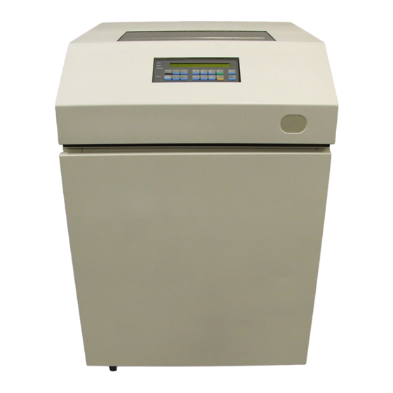
— Provides descriptions of KSSM printer codes and character codes. The IBM 6400-D Generation II Series Printer The IBM 6400-D Generation II Series printers offer software versatility and the latest refinements in line matrix printing technology. Either LQ-1600K, KS, or KSSM will be the standard emulation. To load all of the configuration parameters (forms length, line spacing, etc.), simply power... - Page 13 You can select every function on your printer at the operator panel or you can send commands from the host computer. Cabinet Models Pedestal Models Figure 1. The IBM 6400-D Generation II Series Line Matrix Printer...
-
Page 14: Standard Capabilities
Each configuration provides a different set of configuration menus, control codes, and character sets. The LQ-1600K printer emulation is standard for the IBM Hanzi printer, and the KS or KSSM printer emulation is standard for the IBM Hangul printer. LQ-1600K Emulation The LQ-1600K Emulation is used for the printing of Hanzi characters and supports the GB18030-2000 CAT-A character set. -
Page 15: Optional Feature
Refer to the documentation shipped with the feature for more details. For detailed information about these features or for information on ordering a feature, contact your IBM sales representative or IBM Authorized Remarketeer. Protocols And Emulations A protocol is a set of rules governing the exchange of information between the printer and host computer. - Page 16 Chapter Standard Capabilities...
-
Page 17: Setting Up The Printer
Setting Up The Printer Installation, Attachment, And Configuration Overview DANGER: <4> Do not connect or disconnect any communication port, teleport, attachment connector, or power cord during an electrical storm. <5> Power off the printer and disconnect the power cord before connecting or disconnecting any communication port, teleport, or attachment cable connector. -
Page 18: Before You Begin
“Related Documents” section that begins on page 12. Before You Begin Read this chapter carefully before installing and operating the IBM 6400-D Generation II Series printer. The printer is easy to install, but for your safety and to protect valuable equipment, perform all the procedures in this chapter in the order presented. -
Page 19: Select A Site
Select A Site Select A Site Select a printer site that meets the following requirements: • Cabinet models: Permits complete opening of the printer cover and both doors of the floor cabinet. See dimension requirements in Figure 2. • Pedestal models: Permits complete opening of the printer cover and good access to the paper areas at the front and rear of the printer. - Page 20 Chapter Installation, Attachment, And Configuration Overview 57.5 in. 41.0 in. (146.1 cm) (104 cm) 27.0 in (68.6 cm) 29.0 in. (73.7 cm) 27.0 in. 83.0 in. (68.6 cm) (210.8 cm) 27.0 in. (68.6 cm) 25 in. (63.5 cm) 10.5 in. (26.7 cm) 48.0 in.
-
Page 21: Printer Component
Printer Component Locations Printer Component Locations Familiarize yourself with the names and locations of the printer components shown in the following figures before continuing with the rest of the installation procedure. Tractor Door Paper Scale Paper Support Tractor Lock Vertical Position Knob Forms Thickness Lever... - Page 22 Chapter Printer Component Ribbon Spool Tractor Hub Latch Ribbon Hub Base Casting Shuttle Cover Assembly Vertical Position Knob Forms Thickness Hammer Bank Lever (beneath shuttle Ribbon Guide cover assembly) Ribbon Mask Figure 4. Cabinet Model Component Locations (Cont.)
- Page 23 Printer Component Locations Tractor Door Tractor Lock Operator Panel Base Pan Ribbon Path Diagram Paper Scale Figure 5. Pedestal Model Component Locations...
- Page 24 Chapter Printer Component Ribbon Spool Printer Cover Adjustable Paper Guide Shuttle Cover Assembly Adjustable Hinge Ribbon Hub Forms Thickness Lever Ribbon Guide Ribbon Latch Figure 6. Pedestal Model Component Locations (Cont.)
-
Page 25: Removing Shipping Restraints (Cabinet Models)
Removing Shipping Restraints Locations Removing Shipping Restraints (Cabinet Models) Follow the instructions on the shipping package to perform these steps: 1. Remove shipping restraints from front of shipping pallet. 2. Move printer from shipping pallet. 3. Remove remaining shipping restraints from pallet. 4. -
Page 26: Remove The Cardboard Packing And Envelope
Chapter Removing Shipping Restraints (Cabinet Models) Remove The Cardboard Packing And Envelope Envelope Cardboard Packing Figure 7. Removing the Cardboard Packing and Envelope 1. Raise the printer cover. 2. Remove the cardboard packing. 3. Open the tractor doors. Push the tractor locks down. Slide the tractors outward as far as they will go. -
Page 27: Remove The Hammer Bank Protective Foam
Remove The Hammer Bank Protective Foam Remove The Hammer Bank Protective Foam Hammer Bank Protective Foam Tractor Door Paper Supports (2) Forms Thickness Lever Figure 8. Removing the Hammer Bank Protective Foam 1. Slide the paper supports outward as far as they will go. Lift the hammer bank protective foam and remove it from between the ribbon mask and the platen. -
Page 28: Remove The Platen Protective Foam
Chapter Removing Shipping Restraints (Cabinet Models) Remove The Platen Protective Foam Platen Protective Foam Support Shaft Forms Thickness Lever Figure 9. Removing the Platen Protective Foam 1. Rotate the platen protective foam toward the front of the printer and out from under the support shaft. -
Page 29: Remove Wood Blocks
Remove Wood Blocks Remove Wood Blocks Wood Blocks (6) Figure 10. Removing the Foam Strips and Protective Film 1. Slide the two paper supports toward the center of the support shaft. Position them so that they divide the space between the tractors into three approximately equal segments. -
Page 30: Adjust The Paper Supports
Chapter Removing Shipping Restraints (Cabinet Models) Adjust The Paper Supports Paper Supports (2) Tractor Doors (2) Figure 11. Paper Supports with Directional Arrows Showing the Adjustment Capabilities Slide the paper supports inward until they are approximately four inches from the tractor doors. -
Page 31: Release The Paper Chains
Release The Paper Chains Release The Paper Chains Tie Wraps (2) Paper Chains (8) Bags (2) Figure 12. Releasing the Paper Chains 1. Open the cabinet rear door. 2. Cut the tie wraps and release the paper chains from the bags at the top rear of the printer frame. -
Page 32: Remove Tags
Chapter Removing Shipping Restraints (Cabinet Models) Remove Tags Passive Stacker Paper Fence Tie Wrap Tie Wrap Passive Stacker Paper Fence Red Tag Red Tag Figure 13. Remove Tag and Clamp from Fence or Passive Paper Stacker 1. Remove the tie wrap that is attached to the paper fence. It is marked with a large, red tag. -
Page 33: Removing Shipping Restraints (Pedestal Models)
Remove The Protective Film And Envelope Removing Shipping Restraints (Pedestal Models) Protective films and foam blocks protect printer mechanisms from possible damage during shipment. You must remove these shipping restraints before you operate the printer. Save the foam blocks with the other packing materials. To avoid shipping damage, reinstall the shipping restraints whenever the printer is moved or shipped. -
Page 34: Remove The Hammer Bank Protective Foam
Chapter Removing Shipping Restraints (Pedestal Models) Remove The Hammer Bank Protective Foam Hammer Bank Protective Foam Paper Supports (2) Tractor Door Tractor Lock Figure 15. Removing the Hammer Bank Protective Foam 1. Slide the paper supports outward as far as they will go. 2. -
Page 35: Remove The Platen Protective Foam
Remove The Platen Protective Foam Remove The Platen Protective Foam Platen Protective Foam Support Shaft Forms Thickness Lever Figure 16. Removing the Platen Protective Foam 1. Rotate the forms thickness lever downward (to position “A”). See Figure 16. 2. Rotate the platen protective foam toward the front of the printer and out from under the support shaft. -
Page 36: Attach The Input Paper Shelf And Output Basket
Chapter Removing Shipping Restraints (Pedestal Models) Attach The Input Paper Shelf And Output Basket Optional Paper Output Basket Input Shelf Figure 17. Attaching the Input Paper Shelf and Output Basket 1. Slide the two paper supports toward the center of the support shaft. Position them so that they divide the space between the tractors into three equal segments. -
Page 37: Connect The Interface And Power Cables
Connect The Interface And Power Cables Cabinet Models Connect The Interface And Power Cables Cabinet Models DANGER: <1> Before powering on the printer ensure the printer is plugged into an appropriate power source. Refer to Chapter 2 of the Setup Guide for information on the proper source. <4>... - Page 38 Chapter Connect The Interface And Power Cables Host Interface Connectors Power Switch PC Parallel Interface Connector Connector Cover AC Power Connector Host Interface Cable AC Power Cord Cable Routing Notches Figure 18. Interface and Power Cable Connections, Cabinet Models...
- Page 39 Connect The Interface And Power Cables Cabinet Models Product Description Label Figure 19. Product Description Label Location 1. Check the product description label to verify that the voltage source at the printer site conforms to the requirements specified on page 19. See Figure 19.
- Page 40 Chapter Connect The Interface And Power Cables I/O Connector Serial Connector Figure 21. Removing the I/O Cover 3. Open the cabinet rear door and remove the cover from the I/O connector you have selected. I/O Cable Grommet Figure 22. Cable Routing Notch 4.
- Page 41 Connect The Interface And Power Cables Cabinet Models I/O Plate I/O Connector Cable Connector Figure 23. Cable Connector Attachment 6. Pull the cable up through the notch until it reaches the I/O plate. Attach the cable connector to the printer interface connector previously selected in step 3 of this section.
- Page 42 Chapter Connect The Interface And Power Cables Power Cord Figure 25. Routing the Power Cord 10. Guide the power cord up through the hole in the lower right back corner of the cabinet. Thread the power cord inside the bracket where the gas spring is attached.
-
Page 43: Pedestal Models
Connect The Interface And Power Cables Pedestal Models Pedestal Models DANGER: <1> Before powering on the printer ensure the printer is plugged into an appropriate power source. Refer to Chapter 2 of the Setup Guide for information on the proper source. <4>... - Page 44 Chapter Connect The Interface And Power Cables Parallel Connector Auxiliary I/O Power Switch Serial Connector Figure 27. Interface and Power Cable Connections, Pedestal Models Figure 28. Removing the I/O Cover 5. Remove the cover from the I/O connector you have selected.
- Page 45 Connect The Interface And Power Cables Pedestal Models I/O Cover Figure 29. Attaching the Cable Connector 6. Attach the cable connector to the printer interface connector. Interface Connector Cable Connector Figure 30. Attaching the Power Cord 7. Plug the power cord into the printer AC power connector, then into the AC power outlet.
-
Page 46: Install Basic Components
Chapter Install Basic Components Install Basic Components Attach The Operator Panel Overlay Label Attach the operator panel overlay label by adhering it to your operator panel. See Figure 31. Power READY Ready Processing Micro Line Form Start Cancel Menu Scroll Enter Feed Feed... -
Page 47: Install The Ribbon
Install The Ribbon Install The Ribbon 1. Refer to the ribbon path diagram molded onto the shuttle cover for the following steps. See Figure 3. Figure 32. Opening the Printer Cover 2. Open the printer cover. See Figure 32. 3. On pedestal models, swing the operator panel up and forward to provide clearance. - Page 48 Chapter Install Basic Components Tractor Door Forms Thickness Lever Figure 33. Forms Thickness Lever and Tractor Doors 4. Raise the forms thickness lever as far as it will go. See Figure 33. 5. Open the tractor doors. See Figure 33. 6.
- Page 49 Install The Ribbon Cabinet Models Left Ribbon Spool Forms Thickness Lever Left Ribbon Spool Pedestal Models Forms Thickness Lever Figure 35.Cabinet and Pedestal Models, Interior View of Ribbon Installation 8. Starting from the right ribbon spool, thread the ribbon around the right ribbon guide, under the right tractor door, between the hammer bank cover and ribbon mask, and along the ribbon path to the left ribbon guide.
-
Page 50: Load The Paper
Chapter Install Basic Components Load The Paper Figure 36. Opening the Printer Cover 1. Open the printer cover. See Figure 36. Tractor Door Forms Thickness Lever Figure 37. Forms Thickness Lever 2. Raise the forms thickness lever as far as it will go. See Figure 37. 3. - Page 51 See Figure 39. NOTE: For the pedestal model, this procedure shows loading paper when using the rear paper exit. For information on loading paper using the top paper exit, see the IBM 6400-D Series Operator’s Guide.
- Page 52 Chapter Install Basic Components Paper Tractor Door Tractor Lock Figure 40. The Left Tractor 6. Pull the paper above and behind the ribbon mask, which is a silver- colored metal strip. Refer to the ribbon path diagram on the shuttle cover. Load the paper onto the left tractor sprockets and close the left tractor door.
- Page 53 Load The Paper ATTENTION To avoid damage to the printer caused by printing on the platen, always align the edge of the left tractor door with the number “1” on the paper scale. NOTE: Thin Paper single sheet Medium Paper two-part form Thick Paper six-part form...
- Page 54 Chapter Install Basic Components Right Tractor Door Figure 43. Paper Loaded onto the Right Tractor Sprockets 9. Unlock the right tractor. 10. Load the paper onto the right tractor sprockets. 11. Close the tractor door. 12. Make sure the leading edge of the first sheet of paper is parallel to the tractor splined shaft.
- Page 55 Load The Paper Forms Thickness Lever Figure 44. The Forms Thickness Scale 15. Turn the vertical position knob to feed the paper up into the paper guide assembly. 16. Lower the forms thickness lever, and set it to match the paper thickness. (The A-B-C scale corresponds approximately to 1-, 3-, and 6-part paper thickness.) NOTE: Do not set the forms thickness lever too tightly;...
-
Page 56: Power Paper Stacker Option
Chapter Power Paper Stacker Option Power Paper Stacker Option This section explains how to set up and use the optional power paper stacker. The power stacker mechanically directs the paper from the printer to the paper stacker. Power Paper Stacker Component Locations Familiarize yourself with the names and locations of the components shown in the following illustration before operating the power paper stacker. -
Page 57: Setting Up The Power Paper Stacker
Setting Up The Power Paper Stacker Setting Up The Power Paper Stacker Elevator Disable Switch Elevator Lift Handle Paper Advance Stacker Up Stacker Down Figure 46. Cabinet Model Rear Door Open Showing Rear Operator Panel 1. Turn the printer ON. 2. -
Page 58: Loading And Starting The Power Paper Stacker
Chapter Power Paper Stacker Option Paper Length Indicator Paddle Shaft Bearing Bracket Figure 48. Interior Side View of the Cabinet Model Showing the Paper Length Indicator 5. Set the desired paper length (5-12 inch range), as follows: Grasping the paddle shaft, push or pull toward the front or the rear of the printer, setting the desired paper length by aligning indicator notch on the bearing bracket with the paper length indicator. -
Page 59: Checking The Paper Feed
Checking The Paper Feed Checking The Paper Feed Paper Guide Assembly Figure 49. Checking the Paper Feed (Cabinet Models) 1. Power on the printer. 2. Cabinet models: Check that the paper feeds correctly. Press the Form Feed key several times to ensure that the paper feeds properly beyond the tractors and over the paper guide assembly. - Page 60 Chapter Power Paper Stacker Option Rear Paper Exit Top Paper Exit Paper Guide Paper Guide Assembly Assembly Figure 50. Checking the Paper Feed (Pedestal Models) 3. Pedestal models: NOTE: See the Operator’s Guide for instructions on switching between the two paper exit modes. When using the top exit paper path, paper can not be stacked.
-
Page 61: Top-Of-Form
Set The Top-Of-Form Top-Of-Form The printer must be told where you want the top of your form to be. This procedure must be performed the first time paper is introduced into the printer, as well as every time new paper is loaded. Set The Top-Of-Form Forms Thickness Lever Figure 51. - Page 62 Chapter Top-Of-Form 2. Locate the TOF indicator. It is the small tab located on the left tractor door. See Figure 52. 3. Turn the vertical position knob up or down to align the top of the first print line with the TOF indicator. See Figure 52. Forms Thickness Lever Figure 53.
-
Page 63: Test The Printer
On the configuration printout, examine the print quality of the characters. They should be fully formed and of uniform density. If text characters do not appear correctly formed or if the test does not run, contact your IBM Customer Service Representative. - Page 64 Chapter Test The Printer...
-
Page 65: Configuring The Printer
This chapter explains how to use the operator panel to change individual parameters and save them as a custom configuration. Operator panel keys are described in the IBM 6400-D Series Operator’s Guide. Your programmer’s reference manuals provide information about control codes. -
Page 66: Active Versus Saved Configurations
Chapter The Configuration Main Menu Active Versus Saved Configurations When you change a parameter value, it is active as long as the printer is on or until it is changed again. This is true whether you use the operator panel or send a control code from the host. - Page 67 The Configuration Main Menu Active Versus Saved Configurations Printer Configuration Quick Setup Parallel Control Management see page 102 Interface see page 96 see page 102 see page 105 Recall Custom Set Interface Type Recall Custom Set Interface Selection Save Current Values PC Parallel Save Current Values Display Language...
-
Page 68: Using The Operator Panel
LCD, or Liquid Crystal Display). This chapter provides numerous examples of how to use the operator panel keys and indicator message display to configure the printer. The operator panel key functions are described in detail in your IBM 6400-D Series Operator’s Guide. Program Mode The printer is in Program mode whenever the configuration menus and option values are displayed on the operator panel message display. -
Page 69: Locking The Program Mode
Locking The Program Mode Press the Scroll↑ + Scroll↓ keys at the same time to unlock Program mode. The following message will appear briefly: OPERATOR MENU UNLOCKED Locking The Program Mode When Program mode is locked, you cannot use the operator panel to change the configuration settings. - Page 70 Chapter Printing The Current Configuration The second method for printing the current configuration, as well as several other configurations, is to use the Print Custom Set Values menu option, shown on the following page. CONFIGURATION MANAGEMENT Recall Save Current Delete Change Power Protect Print Custom...
-
Page 71: Factory Default Configuration Values
Factory Default Configuration Values Configuration Factory Default Configuration Values The factory default values are permanently stored as a configuration. They cannot be modified or erased. The parameters which display depend on which interface and emulation is installed. Configuration Below is a representative Hanzi printer factory default configuration. Your factory default configuration will depend on the features installed on your printer. - Page 72 Chapter Factory Default Configuration Values PRINTER CONTROL INTERFACE SELECTION PARALLEL DISPLAY LANGUAGE ENGLISH ALARM CONTROL ALARM ENABLED PRINT DIRECTION BIDIRECTIONAL HEX PRINT MODE DISABLE POWER ON STATE READY PAPER JAM DECTECTION ENABLE FORMS SPEED NORMAL SPEED SET PLATEN AT BOF DISABLE SHUTTLE TIMEOUT 5 SECONDS...
- Page 73 Factory Default Configuration Values Configuration NAME CUSTOM SETS CUSTOM SET 1 CUSTOM SET 2 CUSTOM SET 3 CUSTOM SET 4 CUSTOM/PRELOADED SET 5 CUSTOM/PRELOADED SET 6 CUSTOM/PRELOADED SET 7 CUSTOM/PRELOADED SET 8 RESET CUSTOM SET NAMES CUSTOM SET 1 PARALLEL INTERFACE INTERFACE TYPE IEEE 1284 PC PARALLEL...
- Page 74 Chapter Factory Default Configuration Values PARALLEL HOTPORT TRICKLE TIME 1/4 SEC TIMEOUT 10 SEC. REPORT STATUS DISABLE SERIAL INTERFACE INTERFACE TYPE RS 232 DATA PROTOCOL XON/XOFF BAUD RATE 9600 BAUD DATA BITS STOP BITS PARITY NONE DATA TERMINAL READY READY/BUFFER NOT FULL REQUEST TO SEND TRUE...
- Page 75 Factory Default Configuration Values Configuration PRINT FORMAT CHARACTERS PER INCH 10.0 CHARACTERS PER IN LINES PER INCH 6.0 LINES PER INCH DBCS CPI 6.7 CPI FORMS WIDTH FORMS WIDTH IN INCHES 13.6 INCHES FORMS WIDTH IN MM 345.4 MM FORMS WIDTH IN CHARACTERS 136 CHARACTERS FORMS LENGTH...
- Page 76 INSTALLED MEMORY 32 MB POWER ON TIME: XXX.XX HOURS PRINTING TIME: XX HOURS PRINT STROLES XXXXXX 11 INCH PAGES XXXX RIBBONMINDER NEW RIBBON RIBBON ACTION DISABLE RIBBON TYPE PREMIUM 30 RIBBON END POINT NORMAL NEW RIB. DETECT DISABLE IBM Printer Configuration...
- Page 77 Factory Default Configuration Values Configuration Below is a representation of Hangul’s printer factory default configuration. Your factory default configuration will depend on the features installed in your printer. FACTORY CONFIGURATION File Part Number (See Reference Number) Reference Number xxxxxx Hangul LinePrinter+ Version 1.00A Vx.xxx 31-Oct-03 #xxxxxx...
- Page 78 Chapter Factory Default Configuration Values SETUP PARSE DISABLE SETUP SFCC PRINT DBCS FONT FILE LOG FILE SYSTEM OVERWRITE FILES ENABLE VIEW FILE LIST VERSION 66 BYTES NETWORK.DAT 107 BYTES NETEMB.DAT 107 BYTES NETWLAN.DAT 107 BYTES PTXLOGO.GIF 1210 BYTES 362974.EC1 524544 BYTES ETHDLOAD 789194 BYTES CSTFILES.ALL...
- Page 79 Factory Default Configuration Values Configuration RESPONSE POLARITY STANDARD BUSY ON STROBE ENABLE LATCH DATA ON LEADING EDGE PRIME SIGNAL ENABLE TOF ACTION AT PRIME SIGNAL FORM FEED AT RESET BUFFER SIZE IN KBYTES AUTO TRICKLE DISABLE TRICKLE TIME 1/4 SEC DATAPRODUCTS DATA BIT 8 ENABLE...
- Page 80 Chapter Factory Default Configuration Values SERIAL HOTPORT TRICKLE TIME 1/4 SEC TIMEOUT 10 SEC. REPORT STATUS DISABLE FRAMING ERRORS ENABLE EMULATION CONFIGURATION ASCII PRINTER EMULATION PRINTER EMUL CONFIG DEFINE CR CODE CR = CR AUTO LF ENABLE DEFINE LF CODE LF = CR + LF PRINTER SELECT DISABLE...
- Page 81 INSTALLED MEMORY 32 MB POWER ON TIME: 191.2 HOURS PRINTING TIME: 1.5 HOURS PRINT STROKES 1002049 11 INCH PAGES 1188 RIBBONMINDER NEW RIBBON RIBBON ACTION DISABLE RIBBON TYPE PREMIUM 30 RIBBON END POINT NORMAL NEW RIBBON DETECT DISABLE IBM Printer Configuration...
-
Page 82: Changing Parameters
Chapter Changing Parameters Changing Parameters PRINTER CONTROL Display Alarm Hex Print Interface Print Direction . . . Mode Selection Language Control Bidirectional* Unidirectional * = Factory Default The following procedure shows you how to change a configuration setting. Changing the Print Direction from the factory default setting BIDIRECTIONAL to the setting UNIDIRECTIONAL is provided as an example. - Page 83 Changing Parameters Configuration Step LCD Results Notes PRINTER CONTROL Moves to the PRINT DIRECTION PRINT DIRECTION parameter. Scroll↑ UNTIL PRINT DIRECTION Move into the PRINT DIRECTION BIDIRECTIONAL* menu. The asterisk (*) shows that Enter this is the active value. PRINT DIRECTION Moves to the next available option, UNIDIRECTIONAL the UNIDIRECTIONAL option.
-
Page 84: Saving Your Configuration In A Custom Set
Chapter Saving Your Configuration In A Custom Set Saving Your Configuration In A Custom Set CONFIGURATION MANAGEMENT Recall Save Current Delete Change Power Print Custom Protect Custom Set Values Custom Set On Set Set Values Custom Sets Custom Set 1* Custom Set 2 Custom Set 3 Custom Set 4... - Page 85 Changing Your Configuration In A Custom Set Configuration Step LCD Results Notes 1. Press NOT READY Places the printer in NOT READY mode. Stop OPERATOR MENU Unlocks the Operator Menu, which UNLOCKED allows you to make configuration Scroll↑ Scroll↓ changes. OPERATOR MENU Displays the first Configuration QUICK SETUP...
-
Page 86: Loading Custom Sets Or Factory Default Values
Chapter Loading Custom Sets Or Factory Default Values Step LCD Results Notes OPERATOR MENU Locks Program mode and the LOCKED Operator Menu. Scroll↑ Scroll↓ READY Places the printer in READY mode, prepared for normal Stop operation. 13. It is recommended you make a printout of your current configuration, as described on page Loading Custom Sets Or Factory Default Values * = Factory Default CONFIGURATION... - Page 87 Loading Custom Sets Or Factory Default Values Configuration Step LCD Results Notes 1. Press NOT READY Places the printer in NOT READY mode. Stop OPERATOR MENU Unlocks the Operator Menu, which UNLOCKED allows you to make configuration Scroll↑ Scroll↓ changes. OPERATOR MENU Displays the first Configuration QUICK SETUP...
-
Page 88: Changing The Power On Configuration
Chapter Changing The Power On Configuration Changing The Power On Configuration * = Factory Default CONFIGURATION MANAGEMENT Recall Save Current Delete Print Custom Change Power Protect Custom Set Values Custom Set On Set Custom Sets Set Values Factory Default* Custom Set 1 Custom Set 2 Custom Set 3 Custom Set 4... - Page 89 Changing The Power On Configuration Configuration Step LCD Results Notes 1. Press NOT READY Places the printer in NOT READY mode. Stop OPERATOR MENU Unlocks the Operator Menu, which UNLOCKED allows you to make configuration Scroll↑ Scroll↓ changes. OPERATOR MENU Displays the first Configuration QUICK SETUP Main Menu option, QUICK...
- Page 90 Chapter Changing The Power On Configuration Step LCD Results Notes OPERATOR MENU Locks Program mode and the LOCKED Operator Menu. Scroll↑ Scroll↓ READY Places the printer in READY mode, prepared for normal Stop operation.
-
Page 91: Configuration Menus
Configuration Menus Overview This chapter describes the configuration menus. The Configuration Main Menu options and all of the submenu options are illustrated in menu diagrams and described in detail. For procedures showing how to enter Program mode, save, recall, and print configurations, refer to Chapter 3, “Configuring the Printer.”... -
Page 92: The Configuration Main Menu
Chapter The Configuration Main Menu The Configuration Main Menu Printer Configuration QUICK Control Management SETUP see page 93 see page 96 see page 102 Recall Custom Set Interface Selection Recall Custom Set Save Current Values Display Language Save Current Values Delete Custom Set Alarm Control Change Power On Set... -
Page 93: Quick Setup Menu
Quick Setup Menu Quick Setup Menu * = Factory Default Available for Hanzi LP+ Printers Only QUICK Available for Hangul LP+ Printers Only SETUP from page 92 Recall Save Current Change DBCS to Custom Set Values Power On Set ASCII Factory Default* DBCS Mode* Custom Set 1*... -
Page 94: Print Quality
Chapter Quick Setup Menu Save Current Values This option allows you to save up to eight configurations to meet different print job requirements. This eliminates the need to change the parameter settings for each new job. The configurations are stored in memory and will not be lost if you turn off the printer. -
Page 95: Reset Command
Quick Setup Menu DBCS ASCII Style This option specifies the appearance of single-byte numeric characters. For the Hanzi LP+ printer, select from Normal, Oversize and OCRB. For the Hangul LP+ printer, select from Normal, and OCRB. Graphics Spd-Up This menu is used to increase (speed up) graphic printing speed by turning on Enhanced/Turbo mode. -
Page 96: Printer Control Menu
Chapter Printer Control Menu Printer Control Menu Printer Control from page 92 Interface Display Alarm Print Selection Language Control Direction Alarm Enabled* Bidirectional* English* Parallel* Alarm Disabled Unidirectional Serial Auto Switching Hex Print Power On Paper Jam Forms Mode State Detection Speed Enable*... -
Page 97: Interface Selection
Interface Selection Interface Selection INTERFACE SELECTION enables or disables physical interfaces for attachment switching. If an interface is disabled, it is set offline and any data received will be ignored. Selecting Autoswitching provides automatic interface switching among parallel and serial communication. Only one interface can be enabled at a time. -
Page 98: Hex Print Mode
Chapter Printer Control Menu Hex Print Mode A hex code printout (or hex dump) translates all incoming data to hexadecimal equivalents. A hex dump lists each ASCII data character received from the host computer, together with its corresponding two–digit hexadecimal code. Hex dumps can be used to troubleshoot some types of printer data reception problems. -
Page 99: Shuttle Timeout
Shuttle Timeout In order to retain print quality with this type of form, set the position of the first and last print lines to avoid printing where paper thickness occurs (before and after the perforation). See Forms Length and Perforation Skip for more information. -
Page 100: Ptr Setup Option
Chapter Printer Control Menu When TOP EXIT TEAR mode is selected, the Eject/Restore key operates as follows: • Pressing Eject/Restore causes the paper to advance the bottom of the last printed form to the tear position, ready for the operator to tear off the printed forms. -
Page 101: Delete Files
File System View Files This selection provides a list of files in flash memory. Pressing the Scroll↓ key allows you to view the file size. Delete Files This selection provides a list of files in flash memory. Pressing the Enter key will delete the displayed file from flash memory. -
Page 102: Configuration Management Menu
Chapter Configuration Management Menu Configuration Management Menu Configuration Management from page 92 Recall Save Current Delete Change Custom Set Values Custom Set Power On Set Custom Set 1* Custom Set 1* Factory Default* Factory Default* Custom Set 2 Custom Set 2 Custom Set 1 Custom Set 1 Custom Set 3... -
Page 103: Save Current Values
Save Current Values Custom/Preloaded Sets 5-8 contain configuration sets that assist with the installation and configuration of this printer. These sets are preloaded at the factory. If these sets are not used, you can delete them and create new custom sets. Save Current Values This option allows you to save your custom sets to meet different print job requirements. -
Page 104: Print Custom Set Values
Chapter Configuration Management Menu Print Custom Set Values This option is used to print a listing of various stored printer custom sets. It is recommended that you store the printout of the custom sets in a safe place for quick referral. Name Custom Sets You may specify a 30-character name which can be used to refer to a custom set. -
Page 105: Parallel Interface Menu
Parallel Interface Menu Interface Type Parallel Interface Menu More information about these interfaces is in Chapter 5, “Printer Interfaces.” Parallel Interface from page 92 Interface PC Parallel Dataproducts IEEE 1284 Type Although this interface See page 106 PC Parallel is supported, it is not Dataproducts currently offered on IEEE 1284*... -
Page 106: Pc Parallel Menu
Chapter Parallel Interface Menu PC Parallel Menu The PC PARALLEL menu configures the electrical signals to operate as a PC Parallel printer. PC Parallel from page 105 Data Bit 8 Data Polarity Strobe Response Polarity Polarity Standard* Standard* Standard* Enable* Inverted Inverted Inverted... -
Page 107: Data Polarity
PC Parallel Menu Data Bit 8 The DATA BIT 8 parameter allows access to the extended ASCII character set. This parameter is Enabled by default. When this parameter is Disabled, the printer interprets bit 8 of each incoming data character as a zero, regardless of its actual setting. -
Page 108: Dataproducts Menu
Chapter Parallel Interface Menu Prime Signal ENABLE (the default). When set and the host asserts the PRIME SIGNAL, the parallel port will perform a warm start. • DISABLE. The parallel port will not perform a warm start when the host asserts the PRIME SIGNAL. -
Page 109: Report Status
Parallel Hotport Timeout This is the value used by the printer to time out from the current port and check the other ports for data to print. When the printer has not received data from the host after a certain period of time, it needs to Timeout in order to service the other ports. -
Page 110: Serial Interface Menu
Chapter Serial Interface Menu Serial Interface Menu IMPORTANT The serial interface parameters in the printer must be set to match the serial interface in the host computer (at the other end of the printer data cable). Otherwise, the printer may not operate correctly, and data characters from the computer may not print or may appear as “garbled”... -
Page 111: Interface Type
Interface Type Interface Type This parameter configures the electrical interface for the serial port, as follows: • RS-232 (the default) • RS-422 Data Protocol You may select one of the following serial interface protocols to meet the host interface requirements. •... -
Page 112: Data Bits
Chapter Serial Interface Menu Data Bits The DATA BITS parameter sets the length of the serial data word. The length of the data word must match the corresponding data bits setting in the host computer. • 8 BITS (the default) •... -
Page 113: Request To Send
Request to Send Request to Send This configuration is part of hardware flow control and determines when the REQUEST TO SEND (RTS) signal is generated. This signal indicates whether or not the printer is ready to receive data. • READY AND BUFFER NOT FULL asserts the RTS signal when the printer is READY and the internal serial buffer is not full. -
Page 114: Serial Hotport
Chapter Serial Interface Menu Serial Hotport This option gives the printer the ability to handle multiple data streams simultaneously. It allows the printer to service hosts attached to the serial or parallel ports as if they were the only interface connected. Trickle Time This functionality prevents an attached host from timing out. -
Page 115: Emulation Configuration Menu
This parameter configures the printer emulation and page formatting. The submenu contains only LQ-1600K for the Hanzi printer. The LQ-1600K emulation is described in the IBM 6400-D Generation II Series LQ-1600K Programmer’s Reference Manual. The submenu contains KS and KSSM for Hangul printer. -
Page 116: Print Format
Print Format This parameter configures page formatting. The submenus are described in the IBM 6400-D Generation II Series LQ-1600K Programmer’s Reference Manual or in the IBM 6400-D Generation II Series KS/KSSM Programmer’s Reference Manual . Operator Print Tests Menu Operator Print Tests... -
Page 117: All H's
All H’s All H’s A pattern of all uppercase H’s used to detect missing characters, misplaced dots, smeared characters, or improper phasing. All E’s + FF A pattern of all E’s repeated for ten lines and followed by a form feed to the next page top-of-form, used to identify paper motion or feeding problems, such as paper path obstruction or improper forms. -
Page 118: Printing Time
Chapter Printer Information Menu Printing Time: The cumulative time in hours the printer has actually been printing. The range is 0 through 30,000 hours. Print Strokes: The cumulative number of back–and–forth shuttle strokes the printer has printed during normal operation. The range is 0 through 4,000,000,000 shuttle strokes. -
Page 119: Ribbonminder Menu
Ribbonminder Menu New Ribbon Ribbonminder Menu RibbonMinder** monitors ribbon usage to ensure quality printing. The “RibbonMinder” chapter explains how to use this feature and its options in more detail. RIBBONMINDER from page 92 New Ribbon XXX% Ribbon Action Ribbon Type Premium 30* Press the ENTER key to Disable*... -
Page 120: Ribbon Action
Chapter Ribbonminder Menu Ribbon Action This option allows you to select the following three functions: • DISABLE does not display the RibbonMinder ink consumption percentage. The percentage is calculated but not displayed. • DISPLAY allows you to view the RibbonMinder ink consumption display. •... -
Page 121: Printer Interfaces
(PCBA) and a cable connector for the data line. Communication signals and data may be sent over parallel or serial lines. Each IBM 6400-D Series printer is equipped with three parallel interface protocols and two serial interface protocols. Each interface is selected via the operator panel configuration menu. -
Page 122: Rs-232 And Rs-422 Serial Interface Signals
Chapter RS-232 And RS-422 Serial Interfaces Table 1. RS-232 Serial Interface Connector Pin Assignments Input Signals Output Signals Miscellaneous Signal Signal Signal Received Data (RD) Transmit Data (TD) Chassis Ground Clear To Send (CTS) Request To Send (RTS) Signal Ground Data Set Ready (DSR) Data Terminal Ready (DTR)20 Data Carrier Detect (DCD) 8... -
Page 123: Rs-232 Serial Interface Protocols
RS-232 Serial Interface Protocols RS-232 Serial Interface Protocols DTR — (DTE Ready). The printer controls the data flow by asserting or de- asserting this hardware signal to the host. If there is enough room in the printer buffer, the printer will send a high signal; if the buffer is full the printer will send a low signal. -
Page 124: Rs-232 And Rs-422 Serial Interface Configuration
• Request to Send logic Some application programs require a unique configuration. If the printer is not working properly in the configuration you selected, contact an IBM service representative. One Char Enquiry When enabled a status byte is sent back to the host when the poll character or the command SFCC enquiry is sent to the printer (serial interface only). -
Page 125: Pc Parallel Interface
PC Parallel Interface RS-232 And RS-422 Serial Interface Configuration PC Parallel Interface The PC Parallel interface (also referred to as the “Centronics**” interface) enables the printer to operate with controllers designed for buffered PC Parallel printers. The length of the data cable from the host computer to the printer must not exceed 15 feet (5 meters). -
Page 126: Pc Parallel Interface Signals
TOF Action at Prime Signal (do nothing or form feed) • Buffer Size in kilobytes (1 to 16) Some application programs require a unique configuration. If the printer is not working properly in the configuration you have selected, contact an IBM service representative. -
Page 127: Ieee 1284 Parallel Interface
IEEE 1284 Parallel Interface Operating Modes IEEE 1284 Parallel Interface The IEEE 1284 is a parallel interface with bidirectional capabilities. Features include the following: • Faster data transmission. Timing of the signals has been reduced. • Bidirectional communication. Both the host and the printer can send data. •... -
Page 128: The Negotiation Phase
Chapter IEEE 1284 Parallel Interface The Negotiation Phase The negotiation phase determines which operating mode will be used. At this time, the host and the printer will sense what devices are attached, the supported signals available, and which mode to use. The selected mode, in turn, defines the pins on the 1284 connector. - Page 129 Signals NOTE: The length of the data cable from the host computer to the printer should not exceed 10 meters (32 feet). For greater data reliability, use a cable of 1.8 meters (6 feet) or less. Table 4. Printer 1284 Connector Signals Type of Mode Source of Data Compatible...
-
Page 130: Terminating Resistor Configurations
These 470 ohm pull–up and 1K ohm pull–down terminating resistors are located within the electronics of the machine and should be accessed only by an IBM Customer Service Representative. If the values of these terminating resistors are not compatible with the particular interface driver requirements of your host computer, you may need to have a different resistor combination installed on your printer. -
Page 131: Routine Service And Diagnostics
Periodically remove excess paper chaff and dust from the ribbon and paper paths. If print quality or paper motion deteriorates seriously even after cleaning, contact your IBM service representative for prompt attention. Cleaning Requirements Periodic cleaning ensures efficient operation and clear print quality. If the printer is located in a dusty area or is used for heavy duty printing, clean it more often. -
Page 132: Cleaning Inside The Printer
Chapter Cleaning Requirements Cleaning Inside The Printer Over time, particles of paper, ink, and ribbon accumulate inside impact printers. This is normal. These particles must be removed periodically to avoid degraded print quality. Most paper particles accumulate around the ends of the platen and ribbon path. - Page 133 Cleaning Inside The Printer Ribbon Spool Paper Supports (2) Tractor Door Hub Latch Ribbon Hub Ribbon Path Vertical Position Diagram Knob Shuttle Cover Forms Thickness Assembly Lever Ribbon Guide Figure 66. Cleaning the Printer, Cabinet Models...
- Page 134 Chapter Cleaning Requirements Ribbon Spool Paper Support (2) Right Tractor Shuttle Cover Vertical Assembly Position Knob Operator Panel Base Pan Forms Thickness Lever Ribbon Guide Ribbon Path Diagram Hub Latch Ribbon Hub (2) Figure 67. Cleaning the Printer, Pedestal Models...
-
Page 135: Printer Self-Tests
Printer Self-Test Cleaning Inside The Printer Printer Self-Tests With the exception of testing the interface between the printer and the host computer (and the associated data cable), you do not need to send data from the host computer to the printer to test printer operation. You can use the printer built-in diagnostic tests to check many of the functions of your printer, including print quality and overall operation. -
Page 136: Fault Messages
The second line of the display indicates how to clear the fault. Table 5 explains each fault message and describes how to correct the fault condition. Displayed faults fall into one of two categories: • Operator correctable • IBM Customer Service Representative required to correct... -
Page 137: Fault Correction Procedure
• Run your print job again. If the fault message reappears, power off the printer, then call IBM Customer Service. Otherwise, no further attention is required. The following table explains each fault message and offers suggestions for correcting the fault condition. - Page 138 026 HEX DUMP MODE Printer attach status No action necessary. message. 029 8344 DIAGNOSTIC FAILED Link-level code test Contact IBM service. detects hardware failure. 031 END OF FORMS TIMEOUT A timeout message is Load paper. See Operator’s Guide for...
- Page 139 Delete existing set, then protected. save new set. Refer to page 103 “Delete Custom Set.” 044 EC FIRMWARE/HARDWARE Fatal firmware error on Contact IBM service. ERROR the controller board. 046 EC STOPPED AT STATE Controller self-test and Contact IBM service. <state>...
- Page 140 Power off the printer SEE USERS GUIDE current in fan circuit. and remove paper guide assembly (for instructions, refer to your IBM 6400 Maintenance Information Manual ). Check that the fan cable is connected. Check for obstruction of vents and fan airway;...
- Page 141 Fault Operator Explanation Solution Message Correctable? 082 POWER 8.5 CHECK* Internal power failure. Contact IBM service. SEE USERS GUIDE 083 INTAKE FAN CHECK* Sensors cannot detect Contact IBM service. SEE USERS GUIDE current in fan circuit. 084 POWER 48V CHECK* Internal power failure.
- Page 142 Fault Operator Explanation Solution Message Correctable? 113 INSTRUCTION SET Fatal firmware error on Contact IBM service. SEE USERS GUIDE the controller board. 114 ILLGL OPR ACCESS* Fatal firmware error on Contact IBM service. SEE USERS GUIDE the controller board. 115 ILLGL INSTR ACCESS* Fatal firmware error on Contact IBM service.
- Page 143 Fault Operator Explanation Solution Message Correctable? 135 INVALID STATE* Fatal firmware error on Contact IBM service. SEE USERS GUIDE the controller board. 136 INVALID PARAMETER* Fatal firmware error on Contact IBM service. SEE USERS GUIDE the controller board. 137 SHUTL INVALID CMD* Fatal firmware error on Contact IBM service.
- Page 144 Chapter Fault Messages Fault Operator Explanation Solution Message Correctable? PLEASE WAIT... Printer reset in No action necessary. RESET IN PROGRESS progress. READY Printer state message: No action necessary. printer is online and in communication with host. RIBBON INK OUT RibbonMinder has Replace the ribbon and CHANGE RIBBON determined that the...
-
Page 145: Ribbonminder
RibbonMinder Overview RibbonMinder is a user definable software feature that determines when a ribbon should be changed. It does this by monitoring ink consumption and alerts you when the print quality may fall below a level that you designate. This is especially important if you are printing bar codes to be scanned. This chapter explains how RibbonMinder works and how to configure it to meet your specific print job requirements. -
Page 146: Configuring The Ribbonminder
Chapter Configuring The RibbonMinder Configuring The RibbonMinder This section explains how to unlock the PROGRAM MODE, find the RibbonMinder options, make changes, exit the configuration menu, and lock the PROGRAM MODE. Following this section is a procedure for changing the Ribbon Size option of RibbonMinder. -
Page 147: New Ribbon
New Ribbon New Ribbon The New Ribbon option provides information concerning the percentage of ribbon used and allows you to reset the ribbon life when you replace a worn ribbon. To reset the ribbon life from the operator panel, press Enter while this option is displayed. -
Page 148: Ribbon Type
Chapter Configuring The RibbonMinder Ribbon Type RIBBON TYPE specifies the type of the ribbon installed. When installing or replacing a ribbon, you can adjust the ribbon type by using the Ribbon Type option. The default ribbon type is PREMIUM Press the Scroll↑ and Scroll↓ keys to select the ribbon type. Ribbon End Point RIBBON END POINT allows the printing of more or less pages before the display reaches 0%. -
Page 149: A Printer Specifications
Printer Specifications Ribbon Specifications NOTE: The ribbon life figures listed below are based on IBM tests conducted in accordance with ANSI Standard X3A.182. Actual ribbon life may vary depending upon the user quality criteria, printer condition, machine settings, paper quality, and bar code requirements. Label yield depends on label format, bar code symbology, and other parameters. -
Page 150: Labels
Appendix A Printer Dimensions And Weight Multi-part carbonless, maximum of 6-part forms. Test readability of greater than 4-part forms. Form Thickness: 0.025 inches (0.064 cm) maximum Drive: Adjustable tractors (6-pin engagement) Slew Rate: 6400-D3P 6400-D3C 6400-D6P 6400-D6C 6400-D8P 6400-D8C 16 ips 20 ips 16 ips 25 ips... -
Page 151: Environmental Characteristics
Environmental Characteristics Temperature Environmental Characteristics Temperature Operating: 50° to 104° F (10° to 40°C) Storage: -40° to 158° F (- 40° to 70°C) Relative Humidity Operating: 15% to 80% (noncondensing) Storage: 15% to 90% (noncondensing) Acoustic Noise Level Acoustic Noise Levels 6400-D3P 6400-D6P 6400-D8P 6400-D3C 6400-D6C 6400-D8C per ISO 9296 Printing... -
Page 152: Power Consumption
Appendix A Interfaces Power Consumption Operating Units Power Consumption Mode 6400-D3X 6400-D6X 6400-D8X Watts 30 (60) 45 (80) Standby BTU/Hour 100 (205) 154 (273) Watts Nominal BTU/Hour 1058 1531 Watts 650-900 Maximum BTU/Hour 1075 1500 2211-3062 Numbers represent consumption in Power Saver Mode. Numbers in parenthesis represent standby mode. -
Page 153: Cables
• EIA-232-E Cable • PC-Parallel Cable AS/400: The 6400-D Series is connected to the AS/400 ASCII Workstation Controller via the following IBM cables, available through your IBM service representative: • 20 ft. RS-232 • 40 ft. RS-232 RISC System/6000: For RS-232 attachment to the IBM RISC System/6000, the following are required: •... - Page 154 Appendix A Printing Rates Table 6: DBCS Printing Rates PRINT QUALITY Print Rate (lpm) 6400- 6400- 6400- D3P/D3C D6P/D6C D8P/D8C (with HIGH DENSITY = ON) (with HIGH DENSITY = OFF) NEAR LQ NORMAL HI-SPEED SUPER HI-SPEED ULTRA HI-SPEED Table 7: ASCII Printing Rates PRINT QUALITY Print Rate (lpm) 6400-...
-
Page 155: B A Quick Look At Line Matrix Printing
Matrix Printing Character Formation The IBM 6400-D Series is an impact printer: it creates characters by printing ink dots on paper. Dots overlap to produce a solid–appearing character of uniform density. The dots are made by an assembly of steel hammers mounted on a rapidly oscillating shuttle. -
Page 156: Printing Speed
Unlike serial matrix printers, line matrix printers divide every printable line into horizontal dot rows, then print a dot row of the entire line at every lateral sweep of the shuttle. The IBM 6400-D Series is a line matrix printer. - Page 157 Character Formation Printing rates also vary according to the print quality you select. For example, if you select the Near Letter Quality (NLQ) option, the printer uses more dot rows and slower print strokes to form characters than if you choose the Draft Quality option.
- Page 158 Appendix B Printing Speed...
-
Page 159: Notices
Consult your IBM representative for information on the products and services currently available in your area. Any reference to an IBM product, program, or service is not intended to state or imply that only that IBM product, program, or service may be used. Any functionally equivalent product, program, or service that does not infringe any IBM intellectual property rights may be used instead. - Page 160 Web sites. The materials at those Web sites are not part of the materials for this IBM product and use of those Web sites is at your own risk. IBM may use or distribute any of the information you supply in any way it believes appropriate without incurring any obligation to you.
-
Page 161: Trademarks
Your failure to comply with the terms above terminates this authorization. Upon termination, you must destroy your machine readable documentation. Trademarks The following terms, denoted by an asterisk (*) in this publication, are trademarks of the IBM Corporation in the United States or other countries or both. Application System/400 AS/400... -
Page 162: Product Recycling And Disposal
Recycling facilities may not be available in your area. In the United States, IBM has established a collection process for reuse, recycling, or proper disposal of used batteries and batter packs from IBM equipment. For information on proper disposal of the batteries in this product, please contact IBM at 1-800-426-4333. -
Page 163: Industry Canada Compliance Statement
Properly shielded and grounded cables and connectors must be used in order to meet FCC emission limits. Proper cables and connectors are available from IBM authorized dealers. IBM is not responsible for any radio or television interference caused by using other than recommended cables and connectors or by unauthorized changes or modifications to this equipment. - Page 164 Communication Statements Statement of CISPR 22 Edition 2 Compliance Attention: This is a Class A Product. In a domestic environment this product may cause radio interference in which case the user may be required to take adequate measures. Japanese VCCI Class A Japan JEITA Statement Communication Statements (Taiwan) Warning: This is a Class A product.
- Page 165 Attention: This is a Class A Product. In a domestic environment this product may cause radio interference in which case the user may be required to take adequate measures. Korea China Declaration: This is a Case A Product. In a domestic environment this product may cause radio interference in which case the user may be required to take practical actions.
- Page 166 Dieses Gerät ist berechtigt in Übereinstimmung mit dem deutschen das EG- Konformitätszeichen - CE - zu führen. Verantwortlich für die Konformitätserklärung nach Paragraph 5 des EMVG ist die IBM Deutschland Informationssysteme GmbH, 70548 Stuttgart. Informationen in Hinsicht EMVG Paragraph 3 Abs. (2) 2: Das Gerät erfüllt die Schutzanforderungen nach EN 55022 Klasse A und EN...
-
Page 167: Software License Agreement
Software License Agreement Your printer contains, among other software, Printronix operating software including, but not limited to the Embedded Configurable Operating System (the “eCos Software”) as embedded software. The terms of this Agreement apply only to the eCos Software, and all other embedded software supplied with the printer. - Page 168 Software License Agreement 4. Conflicting Terms You agree that this Agreement provides you no more rights with regards to warranty, support, indemnity or liability terms with respect to Red Hat, Inc., Printronix, Inc. or any contributor to the Embedded Software than that provided by the Red Hat eCos Public License v.1.1 or any express warranty that may be made by Printronix, Inc.
- Page 169 8. Red Hat Statement with regards to eCos Software Part of the software embedded in this product is eCos - Embedded Configurable Operating System, a trademark of Red Hat. Portions created by Red Hat are Copyright (C) 1998, 1999, 2000 Red Hat, Inc. (http://www.redhat.com) All Rights Reserved.
- Page 170 Software License Agreement...
- Page 171 Index Character formation, 155 Characters Per Inch parameter, quick setup, 94 Acknowledge signal, PC parallel interface, 126 Cleaning requirements, 131 ACK/NAK protocol Clear to send (CTS) signal, RS-232 serial interface, RS-232 serial interface, 123 RS-422 serial interface, 123 Communication, bidirectional (1284), 127 Acoustic noise level, 151 Compatibility mode, 127 Adjust Paper Supports, 30...
- Page 172 main, 67, 92 Display/disable RibbonMinder, 120 operator print tests, 116 Distance overview, 91 maximum allowed from host PC parallel, 106 printer installation, 19 Printer Control, 96 Dot matrix character formation, example, 155 printer information, 117 DTR protocol Quick Setup, 93 RS-232 serial interface, 123 serial interface, 110 RS-422 serial interface, 123...
- Page 173 Graphics and vertical formatting features, 15 Installing the printer, 17 Graphics features Interface Epson dot graphics mode, 15 definition, 121 IBM, Epson and PSeries graphics generators, PC parallel, 125 RS-232 serial, 121 Graphics Spd-Up parameter, quick setup, 95 RS-422 serial, 121 Interface selection parameter, 97...
- Page 174 044 EC FIRMWARE/HARDWARE ERROR, Maintenance, 131 046 EC STOPPED AT STATE, 139 Manuals, related to 6400-D Series, 12 056 HAMMER COIL OPEN, 139 Matrix printing, line matrix vs. serial matrix, 155 057 CLOSE PLATEN, 139 Maximum print speed, 14 058 SHUTL JAM, 139 Memory, 117 059 CANCEL PRINT ACTIVE, 139 Messages...
- Page 175 127 ILLEGAL STATE*, 142 printer demonstration, 116 128 INVALID COMMAND*, 142 ripple print, 116 129 INVALID PARAMETER, 142 underlines, 117 130 PAP FEED INCOMPLETE, 142 Optional emulations, loading, 115 131 UNEXPECTED INTERRUPT, 142 Output control features, 14 132 INVALID COMMAND*, 142 automatic underlining and overscoring, 15 133 INVALID STATE*, 142 double high and wide printing, 15...
- Page 176 PC parallel, 106 load, 58 Parallel interface, PC parallel, 125 set up, 57 Parameters start, 58 printing the configuration, 69, 70 Poweron configuration, changing, 88 saving, 84 Power, power consumption, 152 Parity error handling, 123 Predefined configurations, 65 Parity parameter, 112 Preloaded sets, 70 PC parallel interface, 125 Prime signal parameter, 108...
- Page 177 Printing time, 118 Remove Tags, 32 Printout, 98 Report status parameter configuration, 69, 70 serial hotport, 109, 114 Product overview, 6400-D Generation II Series Request to send parameter, 113 printer, 12 Request to send (RTS) signal, RS-232 serial Program mode interface, 122...
- Page 178 type parameter, 120 ETX/ACK protocol, 123 RIBBON INK OUT, 144 framing error handling, 123 Ribbon installation, 47 overrun error handling, 123 Ribbon mask, 52 parity error handling, 123 Ribbon path diagram, 52 pin assignments, 122 RibbonMinder, 145 protocol, 123 configuring, 146 X-ON/X-OFF protocol, 123 display/disable, 147 RS-422 serial interface signals, 122...
- Page 179 Set platen at bottom of form parameter, 98 Temperature requirements, 19, 151 Set ribbon type parameter, 148 Terminating resistor configuration, 130 Setting up the printer, 17 TESTING HARDWARE / PLEASE WAIT, 144 Setup Tests shipping restraints removal after installation, 63 cabinet models, 25 diagnostic, 135 pedestal models, 33...
- Page 180 101 UPPER DRIVER SHORT, 141 102 LOWER DRIVER SHORT*, 141 001 END OF FORMS, 137 107 HAMMER COIL OPEN, 141 002 FORMS JAMMED, 137 11 inch pages, 118 003 FORMS EJECTED, 137 110 STACK OVERFLOW*, 141 004 VIEW FORMS, 137 111 STACK UNDERFLOW, 141 006 HOST REQUESTS ATTN, 137 112 UNDEFINED OPCODE*, 141...
- Page 181 Thank you for your responses. May we contact you? h Yes h No When you send comments to IBM, you grant IBM a nonexclusive right to use or distribute your comments in any way it believes appropriate without incurring any obligation to you. Name...
- Page 182 FIRST-CLASS MAIL PERMIT NO. 40 ARMONK, NEW YORK POSTAGE WILL BE PAID BY ADDRESSEE IBM Corporation IBM Corporation Information Development Information Development IBM Printing Systems IBM Printing Systems Department H7FE Building 004M Depatment 583E Building 003G PO Box 1900 PO Box 1900...
- Page 184 ® Printed in U.S.A 177769-001A *177769-001* S550-0376-00 *07S550037600*...
Need help?
Do you have a question about the 6400-D Generation II Series and is the answer not in the manual?
Questions and answers