Table of Contents
Advertisement
Quick Links
Sig Mfg. Co., Inc....401-7 S Front St...PO Box 520....Montezuma, IA 50171-0520
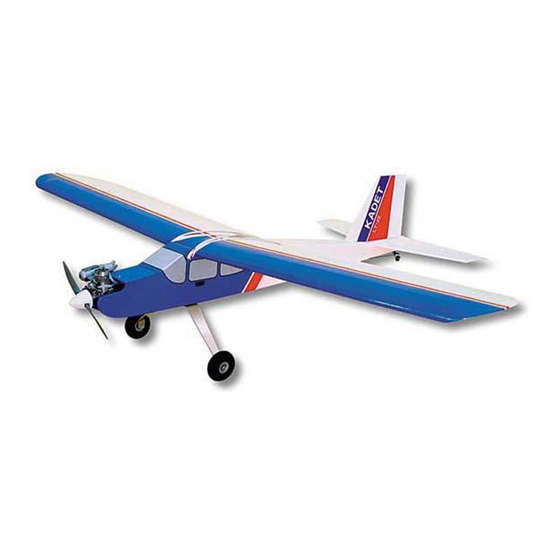
Welcome to the sport of Radio Control flying, and thank you for choosing the SIG KADET LT-25.
We understand how anxious you are to get started building and flying your KADET LT-25, but please take a few minutes right
now to study the full-size plans while you page through this instruction book. This will familiarize you with the general layout of
the airplane and the building sequence, making the entire project easier in the long run.
Introduction
In order for your KADET LT-25 to fly as well as it was designed to, it must be carefully assembled. A model airplane that is not
built properly will not fly properly! Remember to work slowly and follow the instructions exactly. SIG, as the kit manufacturer, can
provide you with a proven aerodynamic design, quality materials, and detailed instructions, but ultimately the flyability of your
finished model depends on how well YOU put it all together.
Customer Service
SIG Mfg. Co., Inc. is totally committed to your success in building and flying the KADET LT-25. Should you encounter any
problem building this kit or find any missing or damaged parts, feel free to contact us.
SIG ORDER LINE: 1-800-247-5008 - (to order parts)
SIG MFG. CO., INC.
SIG MODELER'S HOTLINE: 1-641-623-0215 - (for technical support)
401-7 S Front St
P.O. Box 520
SIG WEB SITE: www.sigmfg.com
Montezuma, IA 50171-0520
E-Mail: mail@sigmfg.com
Advertisement
Table of Contents

Related Manuals for SIG KADET LT-25


Summary of Contents for SIG KADET LT-25
- Page 1 Introduction In order for your KADET LT-25 to fly as well as it was designed to, it must be carefully assembled. A model airplane that is not built properly will not fly properly! Remember to work slowly and follow the instructions exactly. SIG, as the kit manufacturer, can provide you with a proven aerodynamic design, quality materials, and detailed instructions, but ultimately the flyability of your finished model depends on how well YOU put it all together.
-
Page 2: Academy Of Model Aeronautics
Warning! This Is Not A Toy! Flying machines of any form, either model-size or full-size, are not toys! Because of the speeds that airplanes must achieve in order to fly, they are capable of causing serious bodily harm and property damage if they crash. IT IS YOUR RESPONSIBILITY AND YOURS ALONE to assemble this model airplane correctly according to the plans and instructions, to ground test the finished model before each flight to make sure it is completely airworthy, and to always fly your model in a safe location and in a safe manner. - Page 3 Wood parts such as standard stick and sheet stock, leading edges, trailing edges, ailerons, elevator, etc., are all easily identifiable by comparing their shape and dimensions to the plans and the "KADET LT-25 COMPLETE PARTS LIST" (above); therefore we did not feel that there was any need to label these parts. On the other hand, proper identification of the different wing ribs, wing sheeting, fuselage formers, etc., can be confusing because some of them are very similar looking, but in fact...
- Page 4 Any normally ported .25 2-stroke glow R/C engine will provide adequate power to fly the KADET LT-25. We believe that the .25 2-stroke glow R/C engine will be the most commonly used engine in the KADET LT-25, so that is what...
- Page 5 However, if you want to get your KADET LT-25 into the air as quickly as possible, we recommend that you use CA glue for the majority of the assembly of this kit.
- Page 6 • 1/2-Dozen Single-Edge Razor Blades (such as SIG #SH-283) For cutting and trimming covering material. • Long Metal Straight Edge (such as SIG #SE-236) To aid in making long straight cuts in wood and covering material. • Triangle (such as metal SIG #TR-036 or plastic draftsman’s triangle) For squaring up parts during assembly and to aid in making short straight cuts in wood and covering material.
-
Page 7: How To Use These Instructions
Stabilizer, and Fin - which will be assembled directly on top of the plans. The plans also show how we would install a typical radio and engine in the KADET LT-25. By referring to the examples shown on the plan, you should be able to properly install your radio and engine, even if they are not exactly the same as what is shown on the plan. -
Page 8: Wing Construction
WING CONSTRUCTION The KADET LT-25’s wing is designed to be built in two halves - called the LEFT WING PANEL and the RIGHT WING PANEL as shown on fullsize plan sheet 2. Each wing panel will be built directly on top of its own plan, using the plan as a pattern to position the parts. - Page 9 8. Carefully remove all the ribs (W-1 through W-5) from the lasercut sheets #1 through #5. Take time to familiarize yourself with the ribs and how they differ. You will notice that ribs W-1, W-2, W-3, and the front of rib W-4 are smaller than the W-5 ribs to all allow for the 3/32"...
- Page 10 16. After the glue on the center section sheets has cured, cut two 1/8" wide x1/2" long slots in the Top Leading Edge sheet at the W-4 wing rib to accomodate the ends of the two 1/8"x3/16"x24" balsa Top Forward Spars. Glue the Forward Spars into these slots and into the notcheds in the top of all the other wing ribs.
-
Page 11: Joining The Wing Panels
The most important point to have a tight joint at the wing center with no gaps. 23. Use epoxy (either SIG 5-MINUTE or SLOW-CURE) to join the two wing panels. Apply glue generously to the end ribs and the dihedral brace. Work some glue into the slot in each wing root. - Page 12 Also notice that the threaded portions of the Torque Rods should lean back slightly towards the rear of the airplane when the ailerons are in neutral position. That rearward lean provides the Kadet LT-25 with a small amount of "differential" movement in the ailerons (more up than down), which makes for smoother turning.
-
Page 13: Completing The Wing
35. Cut and block sand the end of the aileron to match the shape of the wing tip. Remove the ailerons from the wing and set them aside until time for covering. Completing The Wing 36. Use a sanding block with 80 grit sandpaper to give the entire wing a final sanding. Sand just enough to take off any prominent high spots and to smooth out any mismatched joints between parts. -
Page 14: Fuselage Construction
FUSELAGE CONSTRUCTION NOTE: You will need to have the engine that you will be using before starting on the fuselage construction. 40. Mark the vertical center line and thrust line on the front of firewall F-1. Notice that there are small "tic marks" (cuts) burned iinto the front of F-1 which indicate the proper locations of these lines. - Page 15 Remove the Engine Mounts from the firewall and drill down vertically thru the beams of the Mounts, on the pencil marks, with a 1/8" drill bit (use a drill press if available). 46. Bolt the Engine Mounts back onto the Firewall. Then bolt the engine to the Engine Mounts using the 4-40 x3/4"...
- Page 16 52. Pin the left Fuselage Side down to the building board. Join the right and left Fuselage Sides together by gluing formers F-1 and F-2 into the notches in the left Fuselage Side. Again use a small 90° triangle to keep the formers perpendicular to the fuselage side.
- Page 17 61. Cut two pieces of 1/2" balsa triangle to glue onto the back of the firewall to reinforce the firewall-to-fuselage joint (see full-size plan). Cut notches in the triangle where necessary to clear the blind nuts and pushrod hole. Glue the triangles firmly in place.
-
Page 18: Stabilizer And Elevator
69. Use a long blade on a modeling knife to cut off the excess rudder pushrod tube (from Step 67) and the pull-pull exit tubes (from Step 68). Cut the tubes as close as you can to the fuselage. Then block sand the tubes, and any excess glue, flush with the fuselage. -
Page 19: Fin And Rudder
Fin And Rudder 77. Tape the Fin plan to the building board, and cover with wax paper. Pin down over the plan and glue in place all of the 5/16" balsa laser-cut fin parts. Cut two 5/16" sq. balsa ribs and glue them in place with THIN CA. 78. -
Page 20: General Notes
The choice of which type of covering material to use on your KADET LT-25 is a matter of personal choice. However, if this is your first model airplane, we recommend that you chose one of the popular pre-finished iron-on plastic film coverings. - Page 21 Since it’s very difficult to apply iron-on covering material inside the engine compartment, this area should be fuel proofed by painting it with a fuel-proof hobby paint, before the covering material is applied. We prefer to use SIG SUPERCOAT BUTYRATE DOPE. It’s an excellent fuel proofer. Choose a color of paint that closely matches the color of the covering you will be using.
-
Page 22: Cover The Wing
Cut the .027 x 6’ steel cable provided into two equal length pieces. Attach one end of each cable to each end of the plywood Tiller Bar as shown in this photo. First pass the end of the wire through the hole in the end of the Tiller Bar. - Page 23 Installing Easy Hinges WARNING: SIG EASY HINGES are designed to be used in conjunction with THIN CA glue. Thin CA (any brand) is the ONLY type of glue that can be used on EASY HINGES - do not use any other type of glue on EASY HINGES! 1.
- Page 24 HELPFUL HINT - When applying the side window decals (or any large decal for that matter) it is best to first squirt some type of soapy water solution (window cleaner, SIG Pure Magic Cleaner, etc.) onto the model before laying down the decal.
-
Page 25: Final Assembly
89. Gluing the Stabilizer to the Fuselage: First apply a coat of SIG Epoxy or Thick CA glue to the area of the fuselage where the Stabilizer will go. -
Page 26: Radio Installation
91. Place the Fin/Rudder assembly on the fuselage, sticking the leading edge of the fin through the hole in the top of the fuse. Carefully line up the trailing edge of the fin using the center-line on top of the stab as a guide. Draw along both sides of the fin, marking its location on the top of the fuselage and stab. -
Page 27: Elevator Control
98. Screw one of the Nylon R/C Links onto the threads remaining outside the nylon pushrod tube. Screw it halfway onto the exposed threads - until there are the same amount of exposed threads in front and in back of the R/C Link. 99. -
Page 28: Aileron Control
108. When finished, temporarily plug the elevator servo into the receiver and test the operation of the elevator. If you sense any binding in the elevator movement, find the cause and fix it now. With full up and down movement of the transmitter’s elevator control stick, the elevator should move approximately 9/16"... - Page 29 117. Assemble one Pushrod Connector into the engine’s throttle arm, and the other Pushrod Connector into the throttle servo arm. 118. Stiffen one end of the 1/16" dia. Steel Cable by flowing solder into it. Start by first coating the end of the Cable with "soldering paste".
- Page 30 128. Anchor the loose end of the antenna on the outside of the model near the rear of the fuselage using a small rubber band and a T-Pin (an "antenna hook" is also handy if one came with your radio). Stick the T-Pin into the bottom of the fuselage at an angle, as shown.
-
Page 31: Landing Gear
Slide on the R/C Solder Link. Press the tip of the soldering iron firmly to the outside of the barrel of the R/C Solder Link. Let it heat! Keep the iron against the barrel while you touch the tip of your solder to the joint (not to the soldering iron). When the two parts get hot enough, the solder will melt and flow into the joint. - Page 32 Balance Your Airplane Yes, we know your KADET LT-25 looks done and you’re real anxious to go out and fly it, BUT WAIT A MINUTE - IT’S NOT REALLY DONE YET! It must be balanced! All airplanes, model or full-size, must be accurately balanced in order to fly...
- Page 33 Temperature and humidity changes can cause nylon pushrods, like those on the KADET LT-25’s elevator and rudder, to shrink or expand slightly. If they are just slightly out of neutral, use the trim levers on the transmitter to neutralize them before flying.
-
Page 34: Find A Safe Place To Fly
Find A Safe Place To Fly Don’t try to fly your KADET LT-25 in your backyard, at the local school yard, or in any other heavily populated area! If you have never seen an R/C airplane fly before, you probably don’t realize how much room you really need. It’s more than most people think! A school yard may look inviting, but it is too close to people, houses, power lines, and possible radio interference.
Need help?
Do you have a question about the KADET LT-25 and is the answer not in the manual?
Questions and answers