
Related Manuals for Borri B400R-010-B (C)


Summary of Contents for Borri B400R-010-B (C)
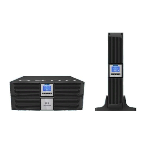
- Page 1 B400R Online UPS User Manual B400R-010-B (C) B400R-020-B (C) B400R-030-B (C) 208/220/230/240VAC...
-
Page 2: Table Of Contents
B400R 1-3kVA User Manual Contents Page 1. SAFETY AND EMC INSTRUCTIONS................3 1.1 Installation ........................3 1.2 Operation........................12 1.3 Maintenance, servicing and faults................12 1.4 Transport ........................15 1.5 Storage.......................... 15 1.6 Standards ........................15 2. DESCRIPTION OF COMMONLY USED SYMBOLS ............16 3. -
Page 3: Safety And Emc Instructions
B400R 1-3kVA User Manual 1. Safety and EMC Instructions Please read carefully through the following user manual and safety instructions before installing and using the UPS. 1.1 Installation Read through the installation instructions before connecting UPS system to the supply. ... - Page 4 1.1.1 Inspection of Unit Inspect the UPS upon arrival. If the UPS is apparently damaged during shipment, please keep the box and packaging material in its original form for the courier and notify the Borri immediately. 1.1.2 Unpacking the Cabinet To unpack the system: 1.
- Page 5 B400R 1-3kVA User Manual...
- Page 6 B400R 1-3kVA User Manual Rack-mount setup The B400R series can also be installed in a 19 inch rack. Both the UPS and external battery enclosure(S) require 2U of rack space each. Use the following procedure to install UPS in a rack: 1.
- Page 7 B400R 1-3kVA User Manual 1.1.4 EBM Installation (Optional) Connecting the EBM in Tower form: 1. Position the extended UPS stands appropriately so that 1 stand will be at either end of the UPS and EBM. 2. Tighten the screw on the metal sheet for stabilization and secure the UPS and EBM together, then lift and place down the UPS and EBM carefully into the stands.
- Page 8 B400R 1-3kVA User Manual Connecting the EBM in a rack form 1. Using the same method as assembling the UPS in a rack form, assemble the EBM into the rack- mounting above or below the UPS. 2. Connect the earth line from UPS (port A) to EBM (port B) 3.
- Page 9 B400R 1-3kVA User Manual Connecting Multiple EBMs The B400R series includes external battery ports that allow users to connect multiple EBMs in order to provide additional backup time. Follow the below procedure to install multiple EBMs. Connecting multiple EBMs in Tower form 1.
-
Page 10: Operation
B400R 1-3kVA User Manual Note: Three or more EBMs can be connected to the UPS in the same way as shown above. Note: After connect the EBMs, please do not forget to set the number of EBMs on LCD, If use the nonstandard EBMs, please call local dealer or distributor for setting method. - Page 11 1.3.3 Time to Replace Batteries When the discharge time is less than 50% of is specified after fully charging, the battery may need to be replaced. Please check the battery connection or contact Borri or your distributor to order new batteries.
- Page 12 B400R 1-3kVA User Manual 1.3.4 Replacing UPS Internal Batteries Follow the below instructions and illustrations to replace batteries: 1. Carefully removed the LCD box, and remove the screws. 2. Slide and Pull the front panel leftward and then take it off. 3.
-
Page 13: Transport
A battery can present a risk of electrical shock and high short circuit current. To properly recycle the used batteries, please follow WEEE Regulations, or your local regulations and procedures from the correct disposal of electrical products. Please contact Borri or your distributor for further information. -
Page 14: Description Of Commonly Used Symbols
B400R 1-3kVA User Manual 2. Description of Commonly Used Symbols Some or all of the following symbols may be used throughout this manual. It is advisable to familiarize yourself with them and understand their meaning: Symbol and Explanation Symbol Explanation Symbol Explanation Alert you to pay... -
Page 15: Introduction
B400R 1-3kVA User Manual 3. Introduction The B400R Series is an uninterruptible power supply incorporating online double-conversion technology. The UPS’s flexibility to handle an array of network devices makes it the perfect choice to protect your LANs, servers, workstations, and other electrical equipment. The double-conversion principle eliminates all mains power disturbances. -
Page 16: Connection
B400R 1-3kVA User Manual 4. Connection 4.1 Inspection Inspect the packaging carton and its contents for damage. Please inform Borri or your supplier immediately should you find signs of damage. Please keep the packaging in a safe place for future use. -
Page 17: Battery Charge
B400R 1-3kVA User Manual (3) EPO Connection: The User can select the polarity of the EPO, the EPO is normally close by default settings. The EPO connector is normally open on the rear panel. Once the connector is closed with a wire, the UPS will stop the output until the EPO status is disabled. -
Page 18: Operation Procedure Of External Battery For Long Backup Time Model ("S" Model)
B400R 1-3kVA User Manual 4.4 Operation procedure of external battery for long backup time model (“S” model) (1) Use the battery pack with voltage: 36VDC for 1KS (12V x3 batteries) for B400R-010-B (C) 48VDC (12V x4 batteries) for the B400R-020-B (C) 72VDC (12V ×6 batteries) for the B400R-030-B (C) Connection of battery quantities that exceed or do not meet the above mentioned quantities will cause abnormal operation or permanent damage to the UPS. -
Page 19: Operation
B400R 1-3kVA User Manual 5. Operation 5.1 Display Panel The UPS has a four-button graphical LCD with dual colour backlight. Standard back-light is used to light up the display with white text and a blue background. When the UPS has a critical alarm, the backlight changes the text to dark amber and the background to amber. - Page 20 B400R 1-3kVA User Manual Table 5-1: Control Button Functions The Button Function Description When the unit has no power and is Power On connected with batteries, press this button for > 100ms & < 1s to power on. When the unit is powered on and in Bypass Turn On mode, press this button for >...
- Page 21 B400R 1-3kVA User Manual The UPS provides useful information about itself, load status, events, measurements, identification, and settings through the front panel display. After powering on, the LCD will display the logo for several seconds and then show the default UPS status summary screen.
-
Page 22: Operating Mode
B400R 1-3kVA User Manual 5.2 Operating mode Different graphic symbols could be displayed dependent on the current operating mode or status. 5.2.1 Line mode An example of the LCD display in Line mode is shown below: Figure 5-3: Line Mode 5.2.2 Battery mode An example of the LCD display in battery mode is shown below: Figure 5-4: Battery Mode... - Page 23 B400R 1-3kVA User Manual 5.2.3 Bypass mode An example of the LCD display in bypass mode is shown in the below diagram. The UPS does not have the backup function when it is in bypass mode. The power used by the load is supplied from the mains via an internal filter.
- Page 24 B400R 1-3kVA User Manual 5.2.5 HE mode (High Efficiency mode) This is also referred to as economy (ECO) mode. After the UPS is turned on, the power used by the load is supplied from the utility power via an internal filter while the utility power is in normal range, so high efficiency can be obtained in the HE mode.
- Page 25 B400R 1-3kVA User Manual 1) This function can be enabled through the LCD settings or the UPS Management software, Winpower. 2) The available UPS capacity is de-rated to 70% in converter mode. 5.2.7 Warning When the warning occurs, it illustrates that there is problems affecting the UPS standard operations. Normally these problems are not fatal and the UPS continues working, but they should be rectified quickly, or the UPS may fail.
- Page 26 B400R 1-3kVA User Manual 5.2.9 Other status When the UPS is overloaded, the alarm will beep twice every second. Some unnecessary loads should be removed from the ups one by one to decrease the loads connected until it reaches a value less than 90% of its nominal power capacity.
-
Page 27: Turning On And Turning Off Ups
2) By pressing the power button continuously for more than 100ms, the UPS will be powered on. At this time the fan begins to rotate, and the LCD will display the Borri logo. The LCD will then show the default UPS status summary screen after the UPS completes its self-test. -
Page 28: Lcd Operation
B400R 1-3kVA User Manual 5.4 LCD operation Apart from the default UPS status summary screen, the user can get access to more information about the UPS current status, details on various measurements, old events which have occurred, the UPS’ own identification, and can change the settings to fit the users own requirements, allowing optimisation of the UPS functionality. - Page 29 B400R 1-3kVA User Manual Figure 5-14: Main menu tree...
- Page 30 B400R 1-3kVA User Manual 5.4.2 The UPS status menu By pressing the button whilst on the menu item “UPS status”, the display will enter the next menu tree. The content of UPS status menu tree is the same as the default UPS summary menu. By pressing the button for >1s, the display will return to the previous menu tree.
- Page 31 B400R 1-3kVA User Manual 5.4.3 The event log menu By pressing the button whilst on the menu item “Event log”, the display will enter the next menu tree. All the old events, alarms and faults will have been recorded and stored in this menu. The information available includes the illustration, the event code, and the operating time of UPS when the event happened.
- Page 32 B400R 1-3kVA User Manual 5.4.4 The measurement menu By pressing the button whilst on the menu item “Measurement”, the display will enter the next menu tree. A lot of useful information can be checked here, including the output voltage and frequency, the output current, the load capacity, the input voltage and frequency, etc.
- Page 33 B400R 1-3kVA User Manual 5.4.5 The control menu By pressing the button whilst on the menu item “Control”, the display will enter the next menu tree. The following options are available: 1) Buzzer mute: the buzzer will stop beeping (enter silence mode). 2) Start battery test: commands the UPS to do a battery test.
- Page 34 B400R 1-3kVA User Manual Figure 5-18: Control menu tree...
- Page 35 B400R 1-3kVA User Manual 5.4.6 The identification menu By pressing the button whilst on the menu item “Identification”, the display will enter the next menu tree. The identification information includes: the UPS serial number, firmware serial number and UPS model type. By pressing the button for >1s, the display will return to the previous menu tree.
-
Page 36: Special Function
B400R 1-3kVA User Manual 6. Special function The B400R series has some special functions, which could satisfy some applications. These functions have their own features; please contact your distributor or Borri for further information before using these functions. 6.1 HE function 6.1.1 Brief introduction to the HE function... -
Page 37: Trouble Shooting
If the UPS system does not operate correctly, check the operating information on the LCD display. Please use the table below to help identify and resolve the problem. If the problem cannot be rectified please contact your distributor or Borri for assistance. Problem... - Page 38 Alarm Code: 71 Bus fault (low / high / UPS Internal fault Please contact your distributor unbalanced / soft start) or Borri for assistance Alarm Code: 22/21/23/25 Inverter fault (low / high / soft UPS Internal fault Please contact your distributor...
-
Page 39: Maintenance
The UPS system contains no user-serviceable parts. If the battery service life (3-5 years at 25°C ambient temperature) has been exceeded, the batteries must be replaced. In the event that you require new batteries please contact your distributor or Borri for assistance. 8.2 Storage If the batteries are stored in temperate climatic zones, they should be charged every three months for 1-2 hours. -
Page 40: Technical Data
B400R 1-3kVA User Manual 9. Technical Data 9.1 Electrical specifications Input Parameters Model No. B400R-010-B (C) B400R-020-B (C) B400R-030-B (C) Phase Frequency (45-55)/(54-66) Hz Max Current (A) 13.5 Output Parameters Power Rating 1kVA/0.9kW 2kVA/1.8kW 3kVA/2.7kW Voltage 208/220/230/240 (± 1%) Frequency 50/60 (±0.2) Hz (Battery mode) Wave form Sinusoidal... -
Page 41: Communication Port
B400R 1-3kVA User Manual 10. Communication Port 10.1 RS-232 and USB communication ports To establish communication between the UPS and a computer, connect the UPS via one of the communication ports by using the appropriate communications cable (USB/RS232). Note: Only one of communication ports can be active at any one time. The USB Port has priority over the RS-232 port. -
Page 42: Installing A Network Management Card (Optional)
B400R 1-3kVA User Manual 10.4 Installing a Network Management Card (optional) Each UPS in the B400R range has one available communication bay, which supports the optional Network Management Card. After you install a Network Management Card, you can connect an environmental monitoring probe to the UPS. - Page 43 B400R 1-3kVA User Manual Dry Out contact schematic Dry In contact schematic The following table shows the options for the dry out/in contacts: Dry Out Signal Description Summary Alarm Activated when any warning occurs On Battery Activated when the UPS is operating from batteries Battery Low Activates with the batteries low alarm (Alarm Code: 12) UPS ok...
-
Page 44: Software
LAN regardless of distance from the UPS. Installation procedure: 1. Go to the website: http://www.borri.co.uk/softwaredownload 2. Choose the operating system you use and follow the instructions described on the website to download the software. 3. When downloading the required files from the internet, enter the serial No.: S11C1-01220- 0100-478DF2A to initiate installation of the software. -
Page 45: Appendix: Rear Panel
B400R 1-3kVA User Manual Appendix: Rear Panel The UPS rear panel description table and pictures are shown as below: Function (B400R 1-3kVA) AC Output EPO / Dry in Communication Port USB Port AC Input Dry Out SNMP Slot RS232 Earth Line Port B400R-010-B (C) &... - Page 46 B400R 1-3kVA User Manual The EBM rear panel description table and picture are shown below: Function (B4BB3, B4BB4 & B4BB5 EBM) Earth Line Port B4BB3, B4BB4 & B4BB5 EBM...
- Page 47 B400R 1-3kVA User Manual Borri Ltd Systems House – Eckington Business Park Rotherside Road – Eckington Sheffield – S21 4HL Tel: +44 01246 431431 Fax: +44 01246 431 444 Email: sales@borri.co.uk Web: www.borri.co.uk Borri S.p.A Via 8 Marzo, 2 52010 Bibbiena (Arezzo)
Need help?
Do you have a question about the B400R-010-B (C) and is the answer not in the manual?
Questions and answers