Table of Contents
Advertisement
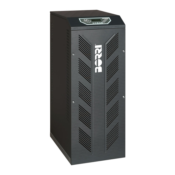
PRODUCT MANUAL
UNINTERRUPTIBLE POWER SUPPLIES
B8031FXS 10kVA (3PH / 1PH)
B8031FXS 15kVA (3PH / 1PH)
B8031FXS 20kVA (3PH / 1PH)
B8033FXS 10kVA (3PH / 3PH)
B8033FXS 15kVA (3PH / 3PH)
B8033FXS 20kVA (3PH / 3PH)
B8033FXS 30kVA (3PH / 3PH)
B8033FXS 40kVA (3PH / 3PH)
B8033FXS 50kVA (3PH / 3PH)
B8033FXS 60kVA (3PH / 3PH)
Descrizione
Rev.
Description
D
Added sizes UPS 50-60kVA
Data
Emesso
Date
Issued
08.04.14
E. Biancucci
English
Approvato
Lingua
Pagina
Approved
Language
Page
F. Berti
E
1
Codice / Code
OMD91046
di Pag.
of Pag.
49
Advertisement
Table of Contents

Subscribe to Our Youtube Channel
Related Manuals for Borri B8031FXS 10kVA


Summary of Contents for Borri B8031FXS 10kVA
-
Page 1: Uninterruptible Power Supplies
PRODUCT MANUAL English UNINTERRUPTIBLE POWER SUPPLIES B8031FXS 10kVA (3PH / 1PH) B8031FXS 15kVA (3PH / 1PH) B8031FXS 20kVA (3PH / 1PH) B8033FXS 10kVA (3PH / 3PH) B8033FXS 15kVA (3PH / 3PH) B8033FXS 20kVA (3PH / 3PH) ... - Page 2 If any typing errors or mistakes are detected, they will be corrected in the new versions of the manual. BORRI holds itself responsible for the information given in the original version of the manual in Italian language. Right of ownership – copying prohibited. BORRI protects its rights on the drawings and catalogues by law.
-
Page 3: Table Of Contents
Index UPS GENERAL DESCRIPTION ............6 RECTIFIER / BATTERY CHARGER ..............9 1.1.1 Battery charger characteristic .............. 10 INVERTER ...................... 10 1.2.1 Operation with non-linear load ............. 12 1.2.2 Overload management ................ - Page 4 4.4.1 Base plan, static load and weights ............26 4.4.2 Dimensions and distances ..............27 4.4.3 Installation criteria ................. 28 4.4.4 Environmental installation conditions ..........28 ELECTRICAL CONNECTION ................ 30 ...
- Page 5 Index of figures Picture 1 – UPS block diagram ........................6 Picture 2 – B8031FXS 10÷20kVA interconnections ..................7 Picture 3 – B8033FXS 10÷60kVA interconnections ..................8 Picture 4 – Rectifier ............................9 Picture 5 – Battery charger characteristic ....................10 ...
-
Page 6: Ups General Description
UPS GENERAL DESCRIPTION The UPS of the B8031FXS 10÷20kVA and B8033FXS 10÷60kVA series is the type “ON LINE DOUBLE CONVERSION” and is connected between main power and user loads (see picture 1). As far as architecture and lay-out is concerned, this project is optimised with particular care in order to make it suitable for applications where reliability and high performances are fundamental for critical loads. -
Page 7: Picture 2 - B8031Fxs 10÷20Kva Interconnections
The UPS of the B8031FXS and B8033FXS series consists of three single-phase AC/AC conversion modules connected to each other in order to obtain UPS units with single or three-phase output, based on the configuration required. The microprocessor checks the operating parameters of each module. The pictures below show the interconnections of the UPS with single or three-phase output. -
Page 8: Picture 3 - B8033Fxs 10÷60Kva Interconnections
Picture 3 – B8033FXS 10÷60kVA interconnections OMD91046 rev D... -
Page 9: Rectifier / Battery Charger
The block diagram in picture 1 shows the UPS subsystems that will be analysed in the following chapters: Rectifier/Battery Charger (R) Inverter (I) Battery (B) Static Switch: Static Inverter Switch (SSI) and Static Bypass Switch (SB) ... -
Page 10: Battery Charger Characteristic
1.1.1 Battery charger characteristic A single-level charge is used. This is an optimal solution with sealed lead acid batteries that, owing to the manufacturing technology, have a very narrow voltage range. In fact, the nominal charging voltage ranges between 2.25÷2.27 V/cell, with a maximum value of 2.3 V/cell. - Page 11 Inductance L2 forms, together with the AC capacitors, a low-pass filter that provides to eliminate the high frequency ripple and keep the total harmonic distortion (THD) of voltage lower than 2% (with linear load). The stability of output voltage and the dynamic response are optimized by using two nested current and voltage loops.
-
Page 12: Operation With Non-Linear Load
1.2.1 Operation with non-linear load A non-linear load is characterized by a high peak current versus its RMS value, that in normal condition would introduce a distortion on the output voltage waveform. The inverter is provided with an instantaneous voltage correction facility, completely managed by the microprocessor, that provides to vary the PWM generation according to the actual output waveform, in order to keep the THD within 5% even with loads having crest factor equal to 3. -
Page 13: Picture 9 - Overload With Bypass Available
1) BYPASS AVAILABLE As soon as an overload is detected the algorithm starts to calculate the increment of the energy. When the threshold value is reached load transferred to bypass. To allow a safe cooling of the components (IGBT’s, transformer) the inverter is switched off for 30 minutes. -
Page 14: Short-Circuit Operation
1.2.3 Short-circuit operation As soon as an output short-circuit is detected (alarm A11), the load is transferred immediately to the emergency line that provides to eliminate the fault thanks to its higher short-circuit current. In case the bypass is not available, the inverter reduces its output voltage and limits its current to 200% for 100ms, and then to 150% for 5 seconds, after that it is switched off (according to EN 62040-3 / EN 50091-3). -
Page 15: Static Switch
STATIC SWITCH The static switch, the diagram of which is shown in picture 6, is composed of thyristors, rated to work continuously at 200% of nominal output power. The components connected to the bypass line are protected by ultra-quick fuses. The static switch is provided with a protection which minimizes the risk caused by a possible return of the inverter voltage in case of emergency mains failure (back-feed protection). -
Page 16: Operating Modes
OPERATING MODES NORMAL OPERATION During normal operation all the circuit breakers/isolators are closed, except for MBCB (maintenance bypass). The three-phase input AC voltage feeds the rectifier via the filter inductor; the rectifier supplies the inverter and compensates mains voltage fluctuations as well as load variation, maintaining the DC voltage constant. -
Page 17: Battery Operation
BATTERY OPERATION In the event of mains failure, or rectifier failure, the battery feeds the inverter without interruption. The battery voltage drops as a function of the magnitude of the discharge current. The voltage drop has no effect on the inverter output voltage since it is kept constant by varying the PWM modulation. -
Page 18: Bypass Operation
BYPASS OPERATION Bypass operation may occur for both manual or automatic change-over. The manual transfer is due to the BYPASS SWITCH, that forces the load to bypass. In the event of a bypass failure the load is transferred back to inverter without interruption. Picture 14 –... -
Page 19: Manual Bypass
MANUAL BYPASS The manual bypass operation is necessary every time the functionality of the UPS needs to be checked or during maintenance or repair works. The manual bypass procedure is described in the UPS operating manual and must be followed carefully in order to avoid damages to the UPS. During the functional check of the UPS, all the breakers can be closed, except for the output breaker OCB, and the full functionality can be tested. -
Page 20: Front Panel
FRONT PANEL The front panel of the UPS, consisting of a four-row alphanumeric display plus 5 function keys, allows the complete monitoring of the UPS status. The mimic flow helps to understand the operating status of the UPS. Picture 18 – UPS front panel FUNCTION BUTTONS The front panel of the UPS is provided with 5 buttons whose functions are indicated in the following table:... -
Page 21: Function Of Mimic Panel Led's
FUNCTION OF MIMIC PANEL LED’S AC line on rectifier input within tolerance GREEN LED 1 Wrong phase rotation GREEN AC mains failure on rectifier input AC bypass line within tolerance GREEN Wrong phase rotation GREEN LED 2 ... -
Page 22: Alarms And Operating Status
ALARMS AND OPERATING STATUS The alphanumeric display offers a complete diagnostic of the system by showing the description of 28 alarms and 6 operating statuses. Each alarm is associated with an internal protection controlled by a microprocessor, which disables certain UPS functions to avoid possible power supply interruptions to the loads. -
Page 23: Measurements On The Display
MEASUREMENTS ON THE DISPLAY Submenu Displayed data Accuracy (1) (2) Rectifier input voltage Rectifier input current INPUT Frequency 0,1 Hz Input power 1 kVA (1) (2) Voltage Current Frequency 0.1 Hz OUTPUT Active power 1 kW Apparent power 1 kVA Load percentage (1) (2) Voltage... -
Page 24: General Technical Information
GENERAL TECHNICAL INFORMATION TECHNICAL DATA For information regarding the technical data of the product, please refer to the technical specification. INSTRUCTIONS FOR INSTALLATION 4.2.1 Receipt of the UPS Please inspect the device before proceeding with installation. If the condition of the packaging or the external appearance of the equipment indicates any kind of damage, contact the shipping company or your dealer immediately. -
Page 25: Handling Of The Ups
HANDLING OF THE UPS Before positioning the UPS, in order to avoid risks of turnover, it’s recommended to move the system on the wood pallet on which the UPS is fixed. Before the positioning in the final location, remove the UPS from the pallet taking away the fastening brackets. -
Page 26: Positioning And Installation
POSITIONING AND INSTALLATION The UPS must be installed in a clean and dry room, preferably not dusty. The User must ensure that there is enough air exchange in the room so that the equipment can be adequately cooled. If this is not guaranteed, the room must be adequately cooled. In case the UPS contains batteries inside (10-15-20kVA), adequate air exchange must be ensured as provided for by EN62040-1, annex N. -
Page 27: Dimensions And Distances
4.4.2 Dimensions and distances Bat tery cabinet Batt ery cabinet Picture 21 – Dimensions and distance from the walls Power (kVA) B8031FXS/ B8033FXS B8033FXS L - mm P - mm H - mm 1200 X (min.) - mm Y (min.) - mm ADD. -
Page 28: Installation Criteria
4.4.3 Installation criteria The UPS must be so installed as to ensure its serviceability and to allow a correct air flow as much as possible. The table below shows the air volume required for an optimal ventilation and cooling of the UPS. Power (kVA) B8033FXS B8031FXS/ B8033FXS... - Page 29 Classification of mechanically active substances (EN 60721-3-3) Class Environmental parameter a) Sand [mg/m 3000 b) Dust (suspension) [mg/m 0,01 c) Dust (sedimentation) [mg/(m ·h) Places where precautions have been taken to minimize the presence of dust. Places away from dust sources Places without any special precaution to minimize the presence of sand or dust, however not in proximity to sand or dust sources...
-
Page 30: Electrical Connection
ELECTRICAL CONNECTION The electrical connection is part of the work which is normally provided by the company that carries out the product installation. For this reason, the UPS manufacturer shall not be held responsible for any damages due to wrong connections. ... - Page 31 During the electrical installation take particular care to respect the phase rotation. Mains connection The connection to the mains must be carried out with protection fuses between the mains and the UPS. The use of differential protection devices in the line supplying the UPS is unadvisable.
- Page 32 Electrical connection data Power (kVA) B8033FXS Rectifier 3x25 3x32 3x32 3x70 3x70 3x100 3x135 Input Fuses (A) Bypass 3x25 3x32 3x32 3x70 3x70 3x100 3x135 Rectifier 4x10 4x25 4x25 4x35 4x35 Input cables Bypass 4x10 4x25 4x25 4x35 4x35 Output cables 4x10 4x25...
-
Page 33: Backfeed Protection Device
BACKFEED PROTECTION DEVICE The back-feed protection device, as indicated by the EN 62040-1 Standard, is optional and can be installed during the UPS production phase; the installation on site can only be carried out by skilled personnel. The device is a contactor that automatically disconnects the bypass line in case of failure of the static switch, in order to avoid voltage feed-back on the input terminals during the a mains failure. -
Page 34: Terminal Boards
TERMINAL BOARDS UPS B8000FXS is provided with terminal boards for the connection of power cables and auxiliary loads. Picture 22 – Terminal board B8031FXS 10-15-20kVA Picture 23 – Terminal board B8033FXS 10-15-20kVA Picture 24 – Terminal board B8033FXS 30-40kVA Picture 25 – Terminal board B8033FXS 50-60kVA OMD91046 rev D... -
Page 35: Electrical Connection Data
4.7.1 Electrical connection data The electrical connection is part of the work which is normally provided by the company that carries out the electrical installation and not by the UPS manufacturer. For this reason, the following recommendations are only an indication, as the UPS manufacturer is not responsible for the electrical installation. -
Page 36: Connection Of Power Cables
CONNECTION OF POWER CABLES For the electric connection of UPS B8000FXS, connect the following cables: DC supply from the battery; AC supply from the rectifier and bypass supply mains; AC output to the loads. Injury hazard due to electric shock! Very high voltages are present at the ends of the cables coming from the battery: ... -
Page 37: Positioning And Connection Of Batteries
POSITIONING AND CONNECTION OF BATTERIES CAUTION A battery can present a risk for electrical shock and high short circuit current. The following precautions should be observed when working on batteries: Remove watches, rings or other metal objects; Use tools with insulated handles; Wear rubber gloves and boots;... -
Page 38: External Battery Cabinet
4.9.1 External battery cabinet The battery cabinet can be used to increase the UPS autonomy for the B8000FXS line 10-15-20kVA where the battery can be fitted into the UPS. IMPORTANT With an external battery the internal battery is not necessary. The external batteries, (consisting of 120 battery blocks, with 6 cells each for 720 cells in total), are installed in the cabinet: - AS533 for 7Ah, 9Ah and 12Ah batteries... -
Page 39: Picture 27 - Dimensions Of The External Battery Cabinet
Picture 27 – Dimensions of the external battery cabinet Cabinet AS553 W (mm) D (mm) H (mm) 1200 L1 (mm) P1 (mm) L2 (mm) 120 x 120 x 120 x 60 x Cabinet AS553 12Ah 12Ah Weight w/o battery (kg) Weight with battery (kg) 1255 1412... -
Page 40: Picture 28 - Battery Cabinet And Ups Connection
4.9.1.2 Connection The following picture shows the electrical connection between the UPS and the external battery cabinet. Picture 28 – Battery cabinet and UPS connection For the connection shown above you can use the cables supplied in the battery cabinet. OMD91046 rev D... -
Page 41: Serial Interfaces
4.10 SERIAL INTERFACES The UPS is provided with serial interfaces for the external communication of the operating status and parameters. RS232/USB: is used for connection to the proprietary programming and control software. MODBUS (OPTIONAL): is used for the transmission of data to the outside via MODBUS protocol (RS485). -
Page 42: Picture 29 - Interfaces Of Ups B8000Fxs
Picture 29 – Interfaces of UPS B8000FXS OMD91046 rev D... -
Page 43: Options
OPTIONS STANDARD OPTIONS INCLUDED TO BE SET VIA SOFTWARE Off-line Programmable rectifier soft-start (Walk-In) Sequential rectifier start for parallel systems (Hold-off) Frequency converter 5.1.1 Off-line The OFF-LINE function can be enabled in the “single configuration” via the Test Software. The load will be supplied by the electronic bypass until the bypass is present and within tolerance. -
Page 44: Options Provided On Request
OPTIONS PROVIDED ON REQUEST THERMAL COMPENSATION PROBE FOR BATTERY VOLTAGE INSULATION TRANSFORMER ON BYPASS LINE SEPARATE INPUT KIT AUTO-TRANSFORMER FOR THE ADAPTATION OF INPUT VOLTAGE ALARM CARD SERIAL INTERFACE RS-485 (ModBus protocol) SNMP ACCESSORY REMOTE PANEL PARALLEL KIT 10. BATTERY CABINET 11. -
Page 45: Bypass Insulation Transformer
5.2.2 Bypass insulation transformer It is used when the input line is without neutral, or the galvanic isolation between the mains and the loads is required. During normal operation the inverter transformer provides for this task, while during the bypass condition the mains feeds the load directly. -
Page 46: Alarm Card
5.2.5 Alarm card UPS B8000FXS, in its full configuration, is provided with a relay card for repeating alarms and operating statuses remotely. Its electric connection is carried out directly on the terminals located on the card. Normal Normal Relay Alarms/Status Status operating Name... -
Page 47: Serial Interface Rs-485 (Mod-Bus Protocol)
5.2.6 Serial interface RS-485 (Mod-Bus protocol) It consists of an additional card which must be installed in a specific space provided on the UPS front. This card contains a “+”, “-“ and “ground” three-pole connector, as well as a serial port RS485 which must be used for the connection to the MODBUS- master. -
Page 48: Connection Kit For External Battery Cabinet
UPS to the additional cabinet. It can be purchased separately in case the external battery is not directly supplied by BORRI. 5.2.11 Wall mounted isolator with battery fuses The isolator with battery fuses is used to separate the UPS from the external battery. -
Page 49: Diesel Generator
5.2.13 Diesel generator The DIESEL GENERATOR Kit allows to preset a UPS for the Diesel Mode function. The diesel generator interface provides to limit the rectifier output voltage in order not to recharge the batteries during the Gen Set operation. In this way the rectifier needs a lower current to feed the DC loads (inverter) and a considerable amount of energy is saved, therefore the rating of the generator power can be lower.
Need help?
Do you have a question about the B8031FXS 10kVA and is the answer not in the manual?
Questions and answers