Table of Contents
Advertisement
Advertisement
Table of Contents
Troubleshooting

Subscribe to Our Youtube Channel
Related Manuals for Borri B500EVO-100-B


Summary of Contents for Borri B500EVO-100-B
-
Page 1: User Manual
B500 Online UPS User Manual B500EVO-100-B B500EVO-200-B 200/208/220/230/240VAC... -
Page 2: Table Of Contents
CONTENT: 1. SAFETY ....................1 1.1 Installation ..................1 1.2 Operation ..................2 1.3 Maintenance, servicing and faults ..........2 1.4 Transport ..................3 1.5 Storage ..................3 1.6 Standards ..................4 2. DESCRIPTION OF COMMONLY USED SYMBOLS ....... 5 3. - Page 3 8.1 Maintenance ................51 8.2 Replacement and Disposal of Batteries ........51 9. COMMUNICATION PORT ..............55 9.1 RS232&USB Interface ..............55 9.2 Intelligent slot ................55 9.3 AS400 Interface (Option) ............. 55 10. SOFTWARE..................57 Free Software Download – WinPower ..........57...
-
Page 4: Safety
1. Safety Please read carefully the following user manual and the safety instructions before installing the unit or using the unit! 1.1 Installation ★ Condensation may occur if the UPS is moved directly from a cold to a warm environment. The UPS must be absolutely dry before being installed. -
Page 5: Operation
★ Earth connection is essential before connecting to the building wiring terminal. 1.2 Operation ★ Do not disconnect the earth conductor cable on the UPS or the building wiring terminals at any time since this will affect the protective earthing of the UPS system and of all connected loads. -
Page 6: Transport
between the battery terminals and the ground. Verify that no voltage is present before servicing. ★ Batteries have a high short-circuit current and pose a risk of shock. Take all precautionary measures specified below and any other measures necessary when working with batteries: -... -
Page 7: Standards
1.6 Standards * Safety IEC/EN 62040-1-1 * EMI Conducted Emission....:IEC/EN 62040-2 Category C3 Radiated Emission....:IEC/EN 62040-2 Category C3 *EMS ESD........:IEC/EN 61000-4-2 Level 3 RS..........:IEC/EN 61000-4-3 Level 3 EFT.........:IEC/EN 61000-4-4 Level 4 SURGE........:IEC/EN 61000-4-5 Level 4 Low Frequency Signals.....:IEC/EN 61000-2-2 Warning: This is a product for commercial applications. If used in an industrial environment extra precautions may be required. -
Page 8: Description Of Commonly Used Symbols
of Commonly Used Symbols Description Some or all of the following symbols may be used in this manual. It is advisable to familiarize yourself with them and understand their meaning:... -
Page 9: Introduction
Computers and Peripherals are thus powered entirely by the UPS. In the event of power failure, the maintenance-free batteries power the inverter. This manual is applicable to the B500EVO-100-B/B500EVO-200-B models. The UPS provides outstanding performance and reliability. The UPS’s unique benefits include: Online UPS design with pure sine wave output. - Page 10 Intelligent Battery Management technology that uses advanced battery management to increase battery service life and optimize recharge time. Selectable High Efficiency mode(ECO mode) or CVCF mode operation. Combo input auto detection Back-feed protection Start-on-battery capability for powering up the UPS even if utility ...
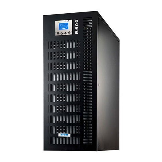
- Page 11 The appearance of B500EVO-100-B/ B500EVO-200-B refers to Fig. 3-1 and Fig. 3-2. Fig. 3-1 the front view of B500EVO-100-B/ B500EVO-200-B...
- Page 12 Side Mounting Bracket B500EVO-100-B REAR VIEW RS232 Parallel Port AS400 Intelligent Slot (optional),etc. Maintenance Back Feed Switch Cover Input Breaker Neutral Switch Cover Terminal Blocks Cover Side Mounting Bracket B500EVO-200-B REAR VIEW Fig. 3-2 the rear view of B500EVO-100-B/ B500EVO-200-B...
-
Page 13: Product Specification And Performance
3.2 Product Specification and Performance 1) General Specification Model B500EVO-100-B B500EVO-200-B 10KVA/9KW 20KVA/18KW Power Rating 50/60 Frequency (Hz) (110-276)VAC (Depends on Load Level) Voltage Input L1/L2/L3:23A MAX L1/L2/L3:46A MAX Current 288VDC Voltage Battery 43A MAX 86A MAX Current 200*VAC/208VAC/220VAC/230VAC/ 240VAC Voltage 45A/48.1A/45.5A/43.5A/41. - Page 14 Output Voltage Power Frequency Current Distortion Overload capacity Regulation Factor tolerance. crest ratio 100%-110% load transfers to Bypass mode after 5 minutes Synchronized 110%-130% load THD<2% Full 50/60Hz10% in transfers to Bypass load (Linear Line mode (AC mode after 1 minutes 1% 0.9 lag Load)/...
-
Page 15: Installation
4. Installation The system may be installed and wired only by qualified electricians in accordance with applicable safety regulations 4.1 Unpacking and Inspection 1. Moving to the installation site The UPS has wheels making it easy to move to the installation site after it has been unpacked. - Page 16 Fig. 4-4. Tools kit Lifter Phillips screwdriver Scissors Wrench Fig. 4-1 Unpacking-step1 Fig. 4-2 Unpacking-step2...
-
Page 17: Input And Output Power Cords And Protective Earth Ground Installation
Fig. 4-3 Unpacking-step3 Fig. 4-4 Unpacking-step4 The shipping materials are recyclable. After unpacking, save them for later use or dispose of them appropriately. 2) Inspect the appearance of the UPS to see if there is any damage during transportation. Do not turn on the unit and notify the carrier and dealer immediately if there is any damage or any parts missing 4.2 Input and output power cords and protective earth ground installation... - Page 18 in a very low temperature environment. In this case it is necessary to wait until the UPS is fully dried out before installation and use. Otherwise there are hazards of electric shock. 4) Once the installation is completed, the side mounting brackets (used in shipping)should be fixed back to ensure the stability of the UPS enclosure.
- Page 19 UPS, please refer to the layout diagram. For the B500EVO-100-B UPS, it is recommended to select the UL1015 8AWG(10mm ) wire or other insulated wire which complies with AWG Standard for the UPS input and output wirings. For the B500EVO-200-B UPS, it is recommended to select the...
- Page 20 12) If it is necessary to connect an inductive load (such as a monitor or laser printer) to the UPS, the start-up power should be used for calculating the required capacity of the UPS. Fig. 4-6 B500EVO-100-B Input and output Terminal Block and ground screw wiring diagram...
- Page 21 If the UPS is used in parallel mode, the Jumper between JP1 and JP2 must be removed. Use cable cross section and protective device specification Model B500EVO-100-B B500EVO-200-B Input L1,L2,L3 Min.conductor cross section[m ㎡] Max.conductor cross section[m ㎡]...
-
Page 22: Operating Procedure For Connecting With The External Battery
Each battery pack consists of 24 pieces of 12V maintenance free batteries in series. To achieve longer backup time, it is possible to connect multi-battery packs, but the principle of “same voltage, same type” should be strictly followed. B500EVO-100-B/B500EVO-200-B, select UL1015 8AWG(10mm... - Page 23 B500EVO-100-B B500EVO-200-B Fig. 4-7 Disconnect the internal battery pack DC connectors...
-
Page 24: Operation
A DC breaker must be connected between the external battery pack and the UPS. The capacity of the breaker must be not less than the data specified in the general specification. 3) Set the external battery pack breaker to “OFF” position and connect the 24 pieces of batteries in series. - Page 25 Fig. 5-1 B500EVO-100-B/B500EVO-200-B On-line UPS Control Panel Table 5-1 Control Button Functions The Button Funtion Illustration When the unit has no power and has connected Power on with battery, press this button for >100ms&<1s to power on When the unit is powered on and in Bypass Turn on mode, press this button for >1s to turn on...
- Page 26 Press this button for >100ms&<1s to scroll down Scroll down the menu option Press this button for >100ms&<1s to select the Enter next present menu option, or enter next menu, but do menu tree not change any setting Press this button for >100ms&<1s to select the Select one present menu option, or enter next menu, but do menu option...
- Page 27 Table 5-3 Buzzer definition UPS condition Buzzer status Fault active Continuous Warning active Beep every second Battery output Beep every 4 seconds, if battery low, buzzer Beeps every second Bypass output Beep every 2 minutes The UPS provides useful information about the UPS itself, load status, events, measurements, identification, and settings through the front panel display.
-
Page 28: Operating Mode
Fig. 5-2 The default LCD display Input information will display rolling 3 phases line Voltage LineL1/LineL2/LineL3 and bypass voltage The more detailed operation of the LCD is illustrated in the chapter of 5.4. 5.2 Operating mode Different graphic symbols can be displayed according to current operating mode or status. - Page 29 Fig. 5-3 Line mode 5.2.2 Battery mode An example of the LCD display in battery mode is shown in the following diagram. Fig. 5-4 Battery mode When the UPS is running in battery mode, the buzzer beeps once every 4 seconds. 5.2.3 Bypass with output The LCD display in bypass mode with output is shown in the following diagram.
- Page 30 5.2.4 Bypass without output The LCD display in bypass mode without output is shown in the following diagram. Fig. 5-6 Bypass mode without output mode 5.2.5 HE mode (High Efficiency It is also called economy mode. After the UPS is turned on, the power used by the load is supplied from the utility power via internal filter while the utility power is in normal range, so the high efficiency can be gained in the HE mode.
- Page 31 software (Winpower, etc.). It should be noted that the transfer time of UPS output from HE mode to INV mode <10ms. This is still too long for some sensitive loads. 5.2.6 Converter mode In converter mode, the UPS will free run with fixed output frequency (50Hz or 60Hz).
- Page 32 Fig. 5-9 Warning 5.2.8 Fault When the fault occurs, it illustrates that some serious problems happened, the UPS will directly cut off the output or transfer to bypass, and keep alarming. The backlight of LCD will also turn to red. The detailed fault table is shown in chapter 7.
- Page 33 nominal power capacity. Fig. 5-11 Overload While doing the battery test, LEDs will be illuminated and the battery test symbol will be shown on the display. Fig. 5-12 Battery test If the battery status detected is “bad battery detected” or “battery disconnected”, the battery failure symbol will be shown and the UPS will alarm.
-
Page 34: Turning On And Turning Off Ups
Fig. 5-13 Battery fails 5.3 Turning on and Turning off UPS Attention: Please switch off the connected loads first before turning on the UPS, and switch on the loads one by one after the UPS is turned on. Switch off all of the connected loads before turning off the UPS. -
Page 35: Lcd Operation
A few seconds later, the UPS turns into Battery mode. If the utility power comes back, the UPS will transfer to Line mode without output interruption of the UPS. 5.3.3 Turning off the UPS with utility To turn off the inverter of the UPS press button continuously for more than 3 seconds and the buzzer will beep 3s. - Page 36 The main menu tree includes six branches: The UPS status menu, event log menu, measurement menu, control menu, identification menu and setting menu. UPS status Alarm # 41 Out put over l oad Event log Alarm Roll Battery Volt: 220V Battery resting Charger level:100% Measurements...
- Page 37 5.4.2 The UPS status menu By pressing on the menu of “UPS status”, the display will enter the next UPS status menu tree. The content of the UPS status menu tree is same as the default UPS status summary menu. By pressing >1s, the display will return the last main menu tree.
- Page 38 All the old events, alarms and faults have been recorded here. The information includes the illustration, the event code, and the operating time of the UPS when the event happened. By pressing <1s, all the events can be displayed one by one. The max number of records is 30.
- Page 39 5.4.4 The measurement menu By pressing on the menu “Measurement”, the display will enter the next measurement menu tree. A lot of detailed useful information can be checked here, for example the output voltage and frequency, the output current, the load capacity, the input voltage and frequency, etc.
- Page 40 UPS which is currently operated in a parallel redundancy system. All other UPSs continue working to supply the load in the parallel system. The “Single UPS battery test” command is designed to control one UPS which is currently operated in a parallel system for single battery testing.
- Page 41 Fig. 5-18 Control menu tree...
- Page 42 5.4.6 The identification menu By pressing on the menu “Identification”, the display will enter the next identification menu tree. The identification information including the UPS serial number, firmware serial number, model type, will be shown here. By pressing >1s, the display will return the last main menu tree. Fig.
-
Page 43: Special Function
6. Special function The B500 series UPS has some features, which could provide for special user applications. These functions have their own features, please contact your local distributor for further information. 6.1 HE function 6.1.1 Brief introduction of HE function If the HE function is enabled, the power used by the load is supplied directly from the mains power via an internal filter whilst the utility power is in normal range. -
Page 44: Parallel Function
will transfer to Battery mode and the load is supplied continuously. The main advantage of this mode is the output frequency is fixed. This can be required for some particularly sensitive loads. This additional protection means that the load capacity of the UPS should be reduced to 60% when used in converter mode. - Page 45 6.3.2 Parallel installation and operation How to install a new parallel UPS system: Before installing a new parallel UPS system, the user needs to prepare the input and output wires, the output breaker, and the parallel cable. Users should use the provided parallel cable with these units wherever possible.
- Page 46 Fig. 6-1 Input and output Terminal Block wiring diagram of B500EVO-100-B...
- Page 47 Fig. 6-2 Input and output Terminal Block wiring diagram of B55EVO-200-B Fig. 6-3 Parallel Installation Diagram...
- Page 48 10) With the output breakers of each unit switched OFF, switch on the input breaker. Look at the LCD screen and check for any displayed fault information. Once done, check and note each UPS output voltage independently. If the voltage difference between the unit is less than 1V then proceed.
- Page 49 Ensure the UPSs shut down totally. Add the new UPS and reinstall the new UPS parallel system by following step 1) to 9) of last chapter - “install a new parallel UPS system”. Switch on the main input breaker and the main output breaker, and set the main maintenance switch or static switch from “BPS”...
-
Page 50: Trouble Shooting
7. Trouble Shooting If the UPS system does not operate correctly, first check the operating information on the LCD display. Please attempt to solve the problem using the table below. If the problem still persists, consult your dealer. 7.1 Trouble Shooting According To Warning Indication Problem Displayed Possible cause Remedy... -
Page 51: Trouble Shooting According To Fault Indication
Para Cable Female The parallel cable is Check the parallel cable. Loss disconnected Para Bat Differ The battery packs of Check if all the battery pack is some UPSs are connected. disconnected Para Byp Differ The M2 bypass input Check the building wiring and of some UPSs is input cable. - Page 52 Byp Overload Fault Overload Check the loads and remove some non-critical loads. Check if some loads are failed. Remove all the loads. Turn off the Output Short Circuit Output short circuit UPS. Check if UPS output and loads is short circuit. Ensure short circuit is removed before turning on again.
-
Page 53: Trouble Shooting In Other Cases
7.3 Trouble Shooting In Other Cases Problem Possible cause Remedy No indication, no No input voltage Check the building wiring and input warning tone even cable. though system is Check if the input breaker is connected to mains closed. power supply BYPASS LED light up Inverter not Press On-Switch “I”... -
Page 54: Battery Maintenance, Replacement And Disposal
8. Battery Maintenance, Replacement and Disposal 8.1 Maintenance ■ Battery replacement should be performed by qualified personnel. This series of UPS only requires minimal maintenance. The batteries used for standard models are regulated sealed lead-acid maintenance free. These models require minimal repairs. - Page 55 8.2 Replacement and Disposal of Batteries 1) Before disposing of batteries, remove conductive jewelry such as necklace, wrist watches and rings. 2) If it is necessary to replace any connection cables, please purchase the original materials from the authorized distributors or service centres, so as to avoid overheat or spark resulting in fire due to insufficient capacity.
- Page 56 1) Remove the front panel and disconnect the connector on the LCD display board. See Fig. 8-1. Fig. 8-1 Battery easy replacement-Step 1 2) Disconnect the battery pack DC connectors and remove the battery fixed plate. See Fig. 8-2. battery fixed plate Fig.
- Page 57 3) Remove the battery pack from the cabinet. See Fig. 8-3. Fig. 8-3 Battery easy replacement-Step 3 4) Replace the old battery packs with the new ones. 5) Reconnect the DC cables. Note: The battery pack is 20kg weight, be careful not to fall off when you operate the battery replacement.
-
Page 58: Communication Port
9. Communication Port 9.1 RS232&USB Interface RS232&USB interface is for the monitoring software and firmware update. Only one option can be used at any given time on an individual product 1) The following is the pin assignment and description of DB-9 connector. - Page 59 Pin # Description Pin # Description UPS Fail Output Bypass Output Summary Alarm Output Battery Low Output Input UPS ON Output Remote Shutdown Input Line Loss Output Common Input Fig. 9-1 signal of AS400 interface...
-
Page 60: Software
RS232 or USB protocol, no matter how far from the UPSs. Installation procedure: 1. Go to the website: http://www.borri.co.uk/softwaredownload 2. Choose the operating system you need and follow the instructions described on the website to download the software. 3. When downloading all required files from the internet, enter the serial No: 511C1-01220-0100-478DF2A to install the software.
Need help?
Do you have a question about the B500EVO-100-B and is the answer not in the manual?
Questions and answers