Table of Contents
Advertisement
Advertisement
Table of Contents

Subscribe to Our Youtube Channel
Related Manuals for Borri B500-R060-C


Summary of Contents for Borri B500-R060-C
-
Page 1: User Manual
B500 Online UPS User Manual B500-R060-C B500-R100-C 208/220/230/240VAC... -
Page 3: Table Of Contents
Contents 1. Introduction ..................1 2. Safety Warnings ................4 2.1 Installation ..................4 2.2 Operation ..................5 2.3 Maintenance, servicing and faults ..........6 2.4 Transport ..................6 2.5 Storage ..................6 2.6 Standards ..................7 3. Installation..................8 3.1 Inspecting the Equipment ............. - Page 4 7.1 Electrical specification ..............49 7.2 Dimension and Weight ..............50 7.3 Operating Environment ............... 50 8. Troubleshooting ................51 8.1 Accessing Alarms and Conditions ..........51 8.2 Typical Alarms and Conditions ............ 53 9. Communication ................58 9.1 USB Interface ................58 9.2 RS-232 Interface .................
-
Page 5: Introduction
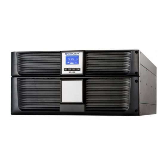
1. Introduction This Borri B500R Series is an uninterruptible power supply incorporating double-conversion technology. It provides protection specifically tailored towards computer equipment, communication systems to computerized instruments. It protects your sensitive electronic equipment from basic power problems such as power failures, power sags, power surges, brownout, and line noise. - Page 6 Fig. 1.2: Online B500-R100-C UPS Online R/T UPS as Tower installation. Fig. 1.3: Online B500-R060-C UPS Fig. 1.4: Online B500-R100-C UPS Providing outstanding performance and reliability, the B500R...
- Page 7 benefits include: Online UPS design with pure sine wave output. True online double-conversion technology with high power density, utility frequency independence, and generator compatibility. Intelligent Battery Management technology that uses advanced battery management to increase battery service life, optimize recharge time.
-
Page 8: Safety Warnings
2. Safety Warnings CAUTION: Before performing the procedures in this document, read and follow the safety instructions and important regulatory information in your Safety, Environmental, and Regulatory Information document. IMPORTANT SAFETY INSTRUCTIONS PLEASE RETAIN THESE INSTRUCTIONS FUTURE REFERENCE. 2.1 Installation ... -
Page 9: Operation
IEC/EN 60934 standard or your local electrical code and have a contact air gap of at least 3 mm. Model 240V 45 amp B500-R060-C 2-pole circuit breaker 70 amp B500-R100-C 2-pole circuit breaker ... -
Page 10: Maintenance, Servicing And Faults
Ensure that no liquid or other foreign objects can enter the UPS. The UPS can be operated by any individual without previous experience. 2.3 Maintenance, servicing and faults The UPS operates with hazardous voltages. Maintenance should be carried out only by qualified maintenance personnel. ... -
Page 11: Standards
2.6 Standards * Safety IEC/EN 62040-1 * EMI Conducted Emission......:IEC/EN 62040-2 Category C2 Radiated Emission......:IEC/EN 62040-2 Category C2 *EMS ESD..........:IEC/EN 61000-4-2 Level 4 RS...........:IEC/EN 61000-4-3 Level 3 EFT..........:IEC/EN 61000-4-4 Level 4 SURGE......... :IEC/EN 61000-4-5 Level 4 CS..........:IEC/EN 61000-4-6 Level 3 Power-frequency Magnetic field.. -
Page 12: Installation
3. Installation This chapter explains: Equipment inspection Unpacking the carton Checking the Accessories UPS setup and installation Connecting the EBM(Extended Battery Modules) Installation requirements 3.1 Inspecting the Equipment If any equipment has been damaged during shipment, keep the shipping cartons and packing materials for the carrier or place of purchse and file a claim for shipping damage. - Page 13 B500-R060-C UPS: Fig. 3.1: Unpacking the Cabinet of Online B500-R060-C UPS B500-R100-C UPS Fig. 3.2: Unpacking the Cabinet of Online B500-R100-C UPS Step 2: Always lift the cabinet carefully out of the outer carton and set it on a flat, stable surface (see Fig. 3.3&3.4).
- Page 14 Place the cabinet in a protected area that has adequate airflow and is free of humidity, flammable gas, and corrosion. Lifting the Cabinet: Fig. 3.3: Lifting the Cabinet of Online B500-R060-C UPS Fig. 3.4: Lifting the Cabinet of Online B500-R100-C UPS Step 3: Discard or recycle the packaging in a responsible manner, or store it for future use.
-
Page 15: Ups Rear Panel
3.3 UPS Rear Panel This section shows the rear panel of the B500R models. B500-R060-C model: Fig. 3.5: Online B500-R060-C Rear Panel B500-R100-C model: Fig. 3.6: Online B500-R100-C Rear Panel 3.4 UPS Front Panel This section shows the front panel of the Online R/T UPS. The Online... -
Page 16: Rack Mount Setup
1. Select the proper holes in the rail for positioning the cabinet in the desired location in the rack. Locate the rails at the bottom of the 3U space for B500-R060-C and 5U space for B500-R100-C allocated for the UPS. - Page 17 Please connect an appropriate breaker between UPS and batteries. Please use the 10AWG wire to connect UPS and EBMS B500-R060-C Model 1. Plug the EBM cable into the UPS battery connector. Fig. 3.9: Plug the EBM cable into the UPS battery connector...
- Page 18 Figure. 3.10: Replace UPS’s front panel and EBM’s front panel. CAUTION: Connect the EBM to protective ground with 8 AWG wire for EBM model before proceeding. B500-R100-C Model:...
-
Page 19: Tower Setup
3.6 Tower Setup Tower setup as below: Fig. 3.11: Tower setup 3.7 Installation of UPS with AC inputs CAUTION: Online B500-R060-C/ B500-R100-C series support different AC power source for input and bypass. So before connecting wires of seperate AC inputs, you should confirm that their earthing systems are identical for both AC inputs. - Page 20 UPS with common Normal and Bypass AC inputs UPS with separate Normal and Bypass AC inputs Earthing systems are identical: Earthing systems are separate: Three different installations can be chosen: 1) Transformer in the Normal AC input. 2) Transformer in the Bypass AC input.
-
Page 21: Power Cables Connection & Startup
3) Both units have a transformer Frequency converter (without Bypass AC input) 4. Power cables connection & Startup This section explains: Access to terminal block Common input sources connection Separate input sources connection Frequency converter connection ... - Page 22 Model B500-R060-C B500-R100-C Protective earthing conductor (8AWG) 10mm2(6AWG) Min cross section Input L, N, G (8AWG) 10mm (6AWG) Min conductor cross section Input fuse Output L,N, (8AWG) 10mm (6AWG) Min conductor cross section External Battery Cabinet Positive Pole(+), Negative (10AWG) 2.5mm...
-
Page 23: Access To Terminal Block
4.1 Access to terminal block Access to terminal block: remove the 2 screws of the terminal block cover. Fig. 4.1: Remove the terminal block for B500-R060-C/ B500-R100-C 4.2 Common input sources connection CAUTION: This type of connection must be carried out by qualified electrical... -
Page 24: Separate Input Sources Connection
Fig. 4.3: Common input sources connection for B500-R060-C Fig. 4.4: Common input sources conection for B500-R100-C 4.3 Separate input sources connection CAUTION: This type of connection must be carried out by qualified electrical... - Page 25 CAUTION: Always connect the earthing wire first! Fig. 4.5: Separate input sources connection for B500-R060-C Fig. 4.6: Separate input sources connection for B500-R100-C...
-
Page 26: Frequency Converter Connection
4.4 Frequency converter connection Fig. 4.7: Frequency converter connection for B500-R060-C Fig. 4.8: Frequency converter connection for B500-R100-C 4.5 UPS Initial Startup To start up the UPS: Verify that the total equipment ratings do not exceed the UPS capacity to... -
Page 27: Parallel Installation And Operation
Make sure that EBMS are connected properly. 1) Set the upstream circuit breaker (not included) to the “I” position (ON). The LCD will display panel illuminates and shows a menu of “Welcome” 2) Verify that the UPS transfers to Bypass mode. 3) Press and hold the button on the UPS front panel for at least three seconds. - Page 28 The parallel system structure is 1+1. As long as the two UPS are equipped with parallel cables, they can be worked in parallel mode to configure a sharing and redundant output power. 4.6.2 Installation and operation NOTE: Before installation and operation, Observe the following requirements.
- Page 29 Fig. 4.9: Parallel systerm wiring diagram of B500-R060-C...
- Page 30 Fig. 4.10: Parallel systerm wiring diagram of B500-R100-C...
- Page 31 Fig. 4.11: Parallel System Installation Diagram...
- Page 32 Switch on the mains Breaker and the input breakers for the two parallel UPS. Press and hold the button continuously for more than 1 second for one UPS in the parallel system to let both UPS turn on into line mode. Regulate the output voltage of the each UPS separately, and check whether the output voltage is less than 0.5V difference between the two UPS units.
- Page 33 5) Connect the cable and wire of the added UPS according to fig4-9 ,fig4-10 and fig4-11. Switch on the input breakers and mains breaker, and make sure that each UPS in the parallel system works correctly in bypass mode. 7) Switch on the O/P breakers and main O/P breaker,transfer the mains mechanical switch or static switch from Utility to the output of the parallel system.
-
Page 34: Operation
Standard back-light is used to light up the display with white text and a blue background. When the UPS has a critical alarm, the backlight changes the text to dark amber and the background to amber. See Figure below Fig. 5.1: B500-R060-C/ B500-R100-C Online UPS Control Panel... - Page 35 Table 5-1 Control Button Functions The Button Function Illustration When the unit is no power and has Power on connected with battery, press this button for >100ms&<1s to power on When the unit is powered on and in Turn on Bypass mode, press this button for >1s to turn on When the unit has been turned on, press...
- Page 36 Table 5-2 Buzzer definition UPS condition Buzzer status Fault active Continuous Warning active Beep every second Beep every 4 seconds, if battery low, buzzer Beep Battery output every second Bypass output Beep every 2 minutes The UPS provides useful information about the UPS itself, load status, events, measurements, identification, and settings through the front panel display.
-
Page 37: Operating Mode
Fig. 5.2: The default LCD display More operation details for LCD are given in chapter 5.4 5.2 Operating mode Different graphic symbols will be displayed according to current operating mode or status. Table 5-3 Status Summary Screens Status Summary Screen Description Normal mode: The UPS is operating in Normal mode from... - Page 38 Battery mode: When the UPS is running in battery mode, the buzzer beeps once every 4 seconds. Fig. 5.4 Bypass with output: The UPS does not have the backup function when it is in bypass mode. The power used by the load is supplied from the utility power via internal filter.
- Page 39 Converter mode In converter mode, the UPS will free run with fixed output frequency (50Hz or 60Hz). Once the mains is lost or abnormal, the UPS will transfer to battery mode and the load is supplied continuously. Fig. 5.8 The function could be enabled through setting software (Winpower, etc.).
-
Page 40: Turning On And Turning Off Ups
Fig. 5.12 Battery fail: If the battery status detected is “bad battery detected” or “battery disconnected”, the symbol of battery failure will be shown and the UPS will alarm. Fig. 5.13 5.3 Turning on and Turning off UPS Attention: The UPS should only be turned on while connecting with the utility for the first time. - Page 41 5.3.2 Turning on UPS without utility Check all the connection is correct. Pressing button continuously for more than 100ms, the UPS will be powered on. The fan begins to rotate and the LCD will show the “Welcome” logo. The LCD will show the default UPS status summary screen after the UPS completes a self-test.
-
Page 42: Lcd Operation
5.4 LCD operation Through the UPS status summary screen, the user is able to discover more useful information about the UPS, such as current status, detail various measurements, event logs, UPS own identification, and change the parameters setting to fit the user requirements, optimize the function of UPS. - Page 43 Fig. 5.14: Main menu tree...
- Page 44 5.4.2 The UPS status menu on the menu of “UPS status”, the display will enter By pressing the next UPS status menu tree. The content of the UPS status menu tree is the same as the default UPS status summary menu. By pressing >1s, the display will return to the last main menu tree.
- Page 45 Fig. 5.15: Event menu tree 5.4.4 The measurement menu on the menu of “Measurement”, the display will By pressing enter the next measurement menu tree. A lot of detailed useful information can be checked here, EG. the output voltage and frequency, the output current, the load capacity, the input voltage and frequency, etc.
- Page 46 Fig. 5.16: Measurement menu tree 5.4.5 The control menu on the “Control” menu, the display will enter the By pressing next control menu tree. Start Battery Test: this one command instructs the UPS to do the battery test. Clear EPO status: once the EPO function is enabled, the UPS output will be cut off immediately and show a warning on LCD.
- Page 47 Reset Fault status: when a fault occurs, the UPS will shift into Fault mode and alarm. To recover to normal status, enter the menu (Control > Reset fault Status) to reset the error status. The UPS will then stop alarming and recover to Bypass mode. Before turning the UPS on again after a fault status by manual operation, the root cause of the fault must be established and eliminated.
- Page 48 Fig. 5.17: Control menu tree 5.4.6 The identification menu on the menu of “Identification”, the display will By pressing enter the next identification menu tree.
- Page 49 The identification information including the UPS serial number, firmware serial number and model type, will be shown here. By pressing >1s, the display will return to the last main menu tree. Fig. 5.18: Identification menu tree 5.4.7 The setting menu Please contact your local distributor for further information before using the settings.
- Page 51 Fig. 5.19: Setting menu tree Example: set rated output voltage value Fig. 5.20: Set rated output voltage value...
-
Page 52: Ups Maintenance
6. UPS Maintenance This chapter explains how to: Care for the UPS Transport the UPS Recycle the used UPS 6.1 UPS Care For the best preventive maintenance, keep the area around the UPS clean and dust-free. If the atmosphere is very dusty, clean the outside of the system with a vacuum cleaner. -
Page 53: Specifications
7. Specifications This chapter provides the following specifications: Electrical specification Dimension and Weight Operating environment Safety and EMC 7.1 Electrical specification Model B500-R060-C B500-R100-C Output Power Capacity 6KVA/5.4KW 10KVA/9KW 208VAC/220VAC/ 208VAC/220VAC/ Voltage Range 230VAC/ 240VAC 230VAC/ 240VAC... -
Page 54: Dimension And Weight
< 5 %@Full load and battery full charged THDI Battery & Charger Voltage 180VDC 240VDC Current Charger current >8A >8A 7.2 Dimension and Weight Model B500-R060-C B500-R100-C Dimension 438*640(594)*129 438*640(594)*215.5 (W*D*H) mm Net Weight (KG) 19.0 26.0 Gross Weight (KG) 22.8 30.8 7.3 Operating Environment... -
Page 55: Troubleshooting
power derating is 1 % every 100 m Acoustic Noise <55dB 8. Troubleshooting The online series UPS is designed for durable, automatic operation and issues alarms to alert you whenever potential operating problems occur. Usually the alarms shown by the control panel do not mean that the output power is affected. - Page 56 To access troubleshooting information using the UPS status menu screen: 1) Press the button for one second or longer to go to the UPS status menu screen. 2) Press the button to access the UPS Status Summary screen. 3) Press the button to access the notice and alarm screens.
-
Page 57: Typical Alarms And Conditions
selection and scroll down to the Event Log menu using the button. 2) Click the button to enter the Event Log list. 3) Scroll through the listed events, notices, and alarms using the button. 8.2 Typical Alarms and Conditions Alarm or Condition Possible cause Action UPS was manually... - Page 58 ground and neutral voltage is > 15v. Utility Abnormal Utility is out of the Check input mains condition tolerance of input Alarm Code: 02 UPS has a unexpected Back feed Transfer to maintenance bypass current on battery bypass and call service. Alarm Code:93 mode Battery voltage is lower...
- Page 59 The alarm resets when the condition becomes inactive. UPS has transferred to The UPS transfers to Battery Inv Overload Fault bypass or fault mode mode if supporting the load. Alarm Code:42 because of overload in Remove some of the inverter mode equipment from the UPS UPS has cut off the output and transferred to fault...
- Page 60 Alarm Code:21 because of BUS. BUS Under Voltage Indicates that the UPS get The UPS transfers to Bypass BUS under voltage fault mode if supporting the load Alarm Code:22 Indicates that the positive BUS Unbalance BUS voltage and negative The UPS transfers to Bypass BUS voltage are too mode if supporting the load Alarm Code:23...
- Page 61 UPS2 turn to fault mode Parallel cable loss In parallel system, parallel Disconnect parallel cable cable disconnect one turn to fault mode Alarm Code: E2 Parallel system UPS1 connect battery, battery status Check battery connect status UPS2 without battery Alarm Code: E6 Line input different Parallel system,UPS1 Check the line input...
-
Page 62: Communication
9. Communication 9.1 USB Interface The USB port is compliance with USB 1.1 protocol for its communication software. 9.2 RS-232 Interface The RS-232 port is available for UPS status monitoring and management by software. The cable pins for the RS-232 communication port are identified in the following illustration. - Page 63 Note: The relay output contact must not be connected to any utility connected circuits. Reinforced insulation to the utility is required. The relay output contact has a maximum rating of 30Vac/1A and 60Vdc/2A normal values. The following figures show schematic of the dry out/in contacts. Normally open Activated closed Dry out contact schematic...
-
Page 64: Intelligent Slot
On Bypass Activated when the UPS has bypass output. Dry in signal Description UPS Off/On Activated by >100ms pulse, the UPS turns off when UPS is on inverter; the UPS turns on when UPS is not on inverter. It is the same as a remote button to control UPS On/Off status. -
Page 65: Software
UPS on the same LAN no matter how far from the UPSs. Installation procedure: 1. Go to the website: http://www.borri.co.uk/softwaredownload 2. Choose the operation system you need and follow the instruction described on the website to download the software. - Page 66 Borri Ltd Systems House – Eckington Business Park Rotherside Road – Eckington Sheffield – S21 4HL Tel: +44 01246 431431 Fax: +44 01246 431 444 Email: sales@borri.co.uk Web: www.borri.co.uk Borri S.p.A Via 8 Marzo, 2 52010 Bibbiena (Arezzo) Italy...
Need help?
Do you have a question about the B500-R060-C and is the answer not in the manual?
Questions and answers