Table of Contents
Advertisement
Advertisement
Chapters
Table of Contents

Subscribe to Our Youtube Channel
Related Manuals for Borri E2001 COMPACT


Summary of Contents for Borri E2001 COMPACT
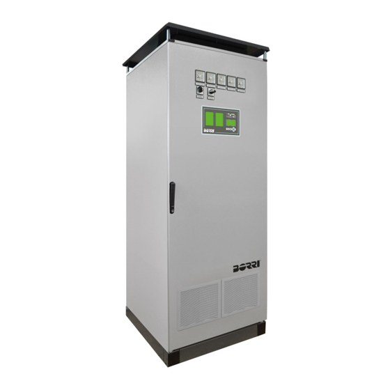
- Page 1 OPERATING AND MAINTENANCE MANUAL E2001 COMPACT – E3001 COMPACT...
- Page 3 UPS OPERATING AND MAINTENANCE MANUAL Indice di sessione Codice 1 – UPS GENERAL DESCRIPTION AND INSTALLATION OMX76006 2 – FRONT PANEL AC-UPS GD 128X64 OMX76007 3 – START-UP, SHUT-DOWN AND MANUAL BYPASS OMX76008 AVVERTENZA This is a product for commercial and industrial application in the second environment - installation restrictions or additional measures may be needed to prevent disturbances Descrizione Data...
-
Page 5: Table Of Contents
UPS general description & installation UPS GENERAL DESCRIPTION AND INSTALLATION Index INTRODUCTION ................5 ENVIRONMENT ....................5 1.1.1 UPS treatment at the end of service life ..........5 1.1.2 Packing ..................... 5 1.1.3 Lead battery ....................5 SAFETY RULES ....................5 1.2.1 Safety of persons .................. - Page 6 UPS general description & installation HANDLING OF THE UPS ................12 POSITIONING AND INSTALLATION ............13 ELECTRICAL CONNECTION ................ 13 BATTERY INSTALLATION ................13 OMX76013 REV. A...
- Page 7 UPS general description & installation Index of pictures Picture 1 - Block diagram ..........................7 Picture 2 - 12 pulses rectifier with galvanic isolation ..................8 Picture 3 - Normal operation........................10 Picture 4 - Load supplied by bypass ......................10 Picture 5 - Rectifier failure or mains failure ....................
- Page 8 UPS general description & installation OMX76013 REV. A...
-
Page 9: Introduction
UPS general description & installation INTRODUCTION 1.1 ENVIRONMENT 1.1.1 UPS treatment at the end of service life The UPS manufacturer undertakes to recycle, by certified companies and in compliance with all applicable regulations, all UPS products recovered at the end of their service life (contact your branch office). -
Page 10: Special Precautions
UPS general description & installation 1.2.3 Special precautions The UPS connection instructions contained in this manual must be followed in the indicated order. Check that the indications on the rating plate correspond to your AC-power system and to the actual electrical consumption of all the equipment to be connected to the UPS. -
Page 11: Ups General Description
UPS general description & installation UPS GENERAL DESCRIPTION 2.1 TYPOLOGY All UPS covered by this manual are on-line, double conversion; the inverter supplies always energy to the load, whether mains is available or not (according to the battery autonomy time). WARNING The UPS output is energized even during mains failure, therefore in compliance with the prescriptions of EN62040-1, the installer will have to identify the line or the plugs... -
Page 12: System Description
UPS general description & installation 2.2 SYSTEM DESCRIPTION 2.2.1 Rectifier It converts the three phase voltage of the mains into continuous DC voltage. It’s designed to supply the inverter at full load and the battery at the maximum recharge current. The system offers very low ripple content during the charging cycle. 2.2.2 12 pulses rectifier The 12 pulses configuration is used to reduce the distortion of the current absorbed from the mains (THD) to a value <12%. -
Page 13: Inverter
UPS general description & installation 2.2.3 Inverter It converts the continuous voltage coming from the rectifier or from the battery into alternating voltage stabilized in amplitude and frequency. The inverter uses IGBT technology with a frequency commutation of approximately 10 KHz. The control electronics is completely digital and uses a 16 Bit P, that, thanks to its processing capability, generates an excellent output sine-wave, which has a very low distortion even in presence of loads having high crest factor currents. -
Page 14: Operating Status
UPS general description & installation 2.3 OPERATING STATUS The following paragraphs show all the possible operating status of the UPS. 2.3.1 Normal operation The inverter is supplied by the rectifier; the load, through the static switch, is supplied directly by the inverter output. Picture 3 - Normal operation 2.3.2 Load supplied by bypass due to inverter fault The load is transferred to bypass through the static switch;... -
Page 15: Rectifier Failure Or Mains Failure
UPS general description & installation 2.3.3 Rectifier failure or mains failure The inverter is supplied by the battery for the required autonomy time; the load, through the static switch, is supplied directly by the inverter output. Picture 5 - Rectifier failure or mains failure 2.3.4 Manual bypass The load is supplied by the mains through the manual bypass;... -
Page 16: Installation
UPS general description & installation INSTALLATION 3.1 RECEIPT OF THE UPS When the UPS is received, please attend immediately to its unpacking and carry-out an accurate visual check to be sure that the equipment has not been damaged during transport. IMPORTANT In case of objections relating to damage incurred during transport these must be immediately notified to the transportation company after receipt of the equipment. - Page 17 UPS general description & installation 3.3 POSITIONING AND INSTALLATION The UPS must be installed in a clean and dry room, preferably not dusty. The User must ensure that there is enough air exchange in the room so that the equipment can be adequately cooled;...
- Page 19 Front panel AC-UPS GD 128x64 FRONT PANEL AC-UPS GD 128X64 Index INTRODUCTION ................5 PANEL FUNCTIONALITY ..............5 FRONT PANEL ................. 6 FUNCTION KEYS ..................... 7 LED FUNCTIONS SYNOPTIC DISPLAY ............8 LCD ....................9 MEASUREMENTS DISPLAY ................. 10 USER COMMANDS MENU ................12 4.2.1 Reset UPS command ................
- Page 20 Front panel AC-UPS GD 128x64 DEFINITION OF THE OPERATING STATUS ..........25 ALARMS: TROUBLESHOOTING ..............28 OMX76014 Rev. A...
- Page 21 Front panel AC-UPS GD 128x64 Index of figures Figure 1 – Front panel ..........................6 Figure 2 – Synoptic panel ..........................8 Figure 3 – Home Page ..........................9 Figure 4 – Home Page - Menu Selection ..................... 9 Figure 5 – Measurements Menu - Selection ....................10 Figure 6 –...
- Page 22 Front panel AC-UPS GD 128x64 OMX76014 Rev. A...
- Page 23 Front panel AC-UPS GD 128x64 INTRODUCTION This manual describes the functions of the graphic front panel 128x64 of the machines AC-UPS. The details follow of all the menus which, via intelligent browsing provide the user with all the useful information to understand the status of the device. The menu, which is password protected, allows you to edit the parameters of the UPS to allow a high level of configurability to be obtained.
-
Page 24: Figure 1 - Front Panel
Front panel AC-UPS GD 128x64 FRONT PANEL The front panel of the rectifier is composed of an alphanumerical graphic display, 20 configurable LEDs and 7 function keys that allow navigation. A synoptic display shows the functional status of the device and the power flow. Figure 1 –... - Page 25 Front panel AC-UPS GD 128x64 3.1 FUNCTION KEYS The following table describes the meaning of the 7 function keys: Function Tests all the leds. Quickly pressing the key only switches on the leds configured in the colour configured. Instead keeping the key pressed, after 5 seconds all the leds in all colours switch on.
-
Page 26: Figure 2 - Synoptic Panel
Front panel AC-UPS GD 128x64 3.2 LED FUNCTIONS SYNOPTIC DISPLAY Figure 2 – Synoptic panel Alternate input mains in tolerance range GREEN LED 1 Alternate input mains fault Rectifier OK GREEN LED 2 Rectifier not OK Battery ok GREEN LED 3 Test battery or battery flat ORANGE Battery disconnected or test unsuccessful... -
Page 27: Figure 3 - Home Page
Front panel AC-UPS GD 128x64 The Home Page of the display shows the name of the device, the status it is in and the voltage and current of output. – Figure 3 Home Page The possible statuses signalled on the display are as follows: ... -
Page 28: Figure 5 - Measurements Menu - Selection
Front panel AC-UPS GD 128x64 From this screen press the ENTER key to access the measurements menus selection menu. – Figure 5 Measurements Menu - Selection The selected menu is that highlighted in bold and positioned at the centre; you can select a different menu, pressing the arrow keys. - Page 29 Front panel AC-UPS GD 128x64 Inverter output voltage Inverter output current INVERTER Inverter output frequency 0.1 Hz Bypass output voltage BYPASS Bypass output frequency 0.1 Hz Output voltage OUTPUT Output current Output frequency 0.1 Hz (1) This voltage measurement refers to the value between the phases (2) The battery measurements are only displayed for configuration with at least one battery installed.
-
Page 30: Figure 7 - Commands Menu - Selection
Front panel AC-UPS GD 128x64 4.2 USER COMMANDS MENU The Commands page allows the user to undertake direct actions on the UPS. – Figure 7 Commands Menu - Selection Commands Commands Description Section Allow UPS reset. Typical use is resetting RESET UPS. -
Page 31: Figure 8 - Commands Menu - Reset Ups
Front panel AC-UPS GD 128x64 4.2.1 Reset UPS command – Figure 8 Commands Menu - Reset UPS The UPS is equipped with internal guards that block the system in the event of particular alarms. Using the arrows, you can change selection between the button and with the V tick and the button with the X. - Page 32 Front panel AC-UPS GD 128x64 4.2.2 Battery test commands The UPS can give commands to execute the following battery tests (where available): Request boost: forces the machine in Boost mode for 60 seconds; after this interval if the amperometric relay does not intervene the machine returns to buffer mode.
-
Page 33: Figure 9 - Alarms Menu - Selection
Front panel AC-UPS GD 128x64 4.3 BASIC DIAGNOSTICS From the Alarms page, you can access the display page of the log or the display page of machine status with all the alarms and the active statuses. – Figure 9 Alarms Menu - Selection 4.3.1 Device status This screen displays an alarm (or status) enabled on the machine. -
Page 34: Figure 11 - Alarms Menu - Log
Front panel AC-UPS GD 128x64 4.3.2 Log The Log page displays the log of machine events. One element at a time is displayed according to the structure visible in the following screen. – Figure 11 Alarms Menu - Log All the visible events on the page are similarly represented with: - event code (a star beside the alarm code indicates alarm reset);... - Page 35 Front panel AC-UPS GD 128x64 4.3.3 List of alarms and statuses of the rectifier ALARM DESCRIPTION OF THE ALARM ALARM DESCRIPTION OF THE ALARM Mains fault Disconnected probe Rectifier fuses blown Inverter off by user Rectifier high temperature Inverter input voltage not OK Rectifier overload Inverter high temperature Max rectifier voltage...
-
Page 36: Figure 12 - Settings Menu - Selection
Front panel AC-UPS GD 128x64 4.4 SETTINGS AND ADVANCED OPERATIONS A password is required to access the Settings page. Once the correct password is entered, you access the Settings page with a list to scroll of the pages which can be accessed. - Page 37 Front panel AC-UPS GD 128x64 4.4.1 Input Settings The Input Settings menu allows changing the acceptability intervals for voltage and frequency of the mains. Drop-down menu Data displayed Sets the percentage of the upper acceptability MAX VOLTAGE (Maximum voltage) threshold of the RMS input mains voltage. Sets the percentage of the lower acceptability MIN VOLTAGE (Minimum voltage)
- Page 38 Front panel AC-UPS GD 128x64 4.4.4 Battery settings The Battery settings menu only available for configurations with the batteries installed, allows setting the battery data. Drop-down Section Description menu Sets the dimension of the battery (e.g. SIZE following replacement of the battery after (Battery dimension) rectifier start-up).
- Page 39 Front panel AC-UPS GD 128x64 4.4.5 Battery charger settings The Battery charger settings menu only available for configurations with the batteries installed, allows setting the float charge parameter for buffer, manual and rapid. Drop-down Section Description menu VOLTAGE Sets the floating charge. (Floating charge) CURR.
-
Page 40: Figure 13 - Settings Menu - Clock
Front panel AC-UPS GD 128x64 4.4.6 DC Voltage Settings The DC Voltage Settings menu allows you to set the output voltage of the rectifier. Drop-down menu Description MAX VOLTAGE Sets the threshold for alarm A5 (Maximum output voltage) MAX VOLT. DELAY Sets standby time on alarm A5 activation (Max voltage standby time) -
Page 41: Figure 14 - Info Menu - Firmware Versions
Front panel AC-UPS GD 128x64 4.5 INFO The Info page provides some general information on the rectifier logic and the panel logic. Drop-down menu Data displayed Firmware version of the UPS (Static Micro- FW VERSIONS Controller, Rectifier DSP and Inverter DSP). (Firmware Versions) Front panel firmware version. -
Page 42: Figure 15 - Home Page If Alarms Present
Always use protective equipment designed for each type of activity; The instructions contained in the manuals must be strictly followed; If in doubt or you cannot solve the problem, please contact Borri immediately. OMX76014 Rev. A... - Page 43 Front panel AC-UPS GD 128x64 5.1 DEFINITION OF THE OPERATING STATUS Status RECTIFIER ON Description The rectifier bridge is on. Operating The rectifier is on. condition Status RECTIFIER OK Description The rectifier is working properly. Operating The rectifier has no system alarm on (e.g. ROCB open A14, etc.). condition Status FLOATING CHARGE...
- Page 44 Front panel AC-UPS GD 128x64 Status SLAVE Description In parallel configuration the unit is the SLAVE. Operating The SLAVE status is enabled when it is connected to another condition rectifier with the share current enabled. Status PARALLEL OFF Description The current allocation algorithm is disabled Operating In the MASTER unit, this condition is alternative to S9-MASTER condition...
- Page 45 Front panel AC-UPS GD 128x64 Status SLAVE SYNCHRONISED Description The inverter is synchronised with the MASTER. Operating Status active only in configurations with the inverter parallel and condition only on SLAVE machines. The inverter is synchronised with the MASTER output. Status BYPASS OK Description...
- Page 46 Front panel AC-UPS GD 128x64 5.2 ALARMS: TROUBLESHOOTING Alarm MAINS FAULT Description The voltage or frequency of the input line are out of tolerance. Possible Mains instability or fault. causes Wrong rotation. Solutions 1. Check connections to the electrical mains. 2.
- Page 47 Front panel AC-UPS GD 128x64 Alarm MINIMUM RECTIFIER VOLTAGE Description The direct voltage measured has surpassed the lower threshold value. Possible Circuit fault of control or measurement. causes Solutions 1. Check the actual value of the direct voltage measured and reset the device.
- Page 48 Front panel AC-UPS GD 128x64 Alarm RICB OPEN Description The input switch is open. Possible Input switch is open. causes Switch auxiliary contact faulty. Solutions 1. Check the switch auxiliary contact is working. 2. If the alarm persists, contact our technical support service. Alarm BCB OPEN Description...
- Page 49 Front panel AC-UPS GD 128x64 Alarm MIN BATTERY LEVEL 2 Description The battery reaches the second minimum level. Possible Level 2 flat battery due to mains fault. causes Rectifier fault. Solutions 1. Check the actual value of the battery voltage. 2.
- Page 50 Front panel AC-UPS GD 128x64 Alarm MANUAL INTERRUPTED Description Manual charge shut-off. Possible Emergency level setting. causes Buffer charge setting. Disabled manual charge. Rectifier off. Solutions 1. Check which alarms are present and execute the indicated procedures.
- Page 51 Front panel AC-UPS GD 128x64 Alarm RECTIFIER PARALLEL FAULT Description In parallel configuration of the rectifier, the system cannot manage to sub-divide the load even if the conditions are present. Possible Current sensor disconnected. causes The parallel switch contacts are interrupted. Solutions 1.
- Page 52 Front panel AC-UPS GD 128x64 Alarm DISCONNECTED PROBE Description The temperature probe (if present) is disconnected. Possible Connection fault in probe cabling. causes Solutions 1. Check the probe connection. 2. If the alarm persists, contact our technical support service. Alarm INVERTER OFF BY USER Description...
- Page 53 Front panel AC-UPS GD 128x64 Alarm ICB OPEN Description The input switch of the inverter ICB is open. Possible Inverter input switch ICB open. causes Switch auxiliary contact faulty. Solutions 1. Check the switch auxiliary contact is working. 2.
- Page 54 Front panel AC-UPS GD 128x64 Alarm SHORT CIRCUIT Description Inverter output short circuit Possible Inverter output short circuit causes Solutions 1. Eliminate the causes of the short circuit in inverter output 2. If the alarm persists, contact our technical support service. Alarm INVERTER THERMAL IMAGE Description...
- Page 55 Front panel AC-UPS GD 128x64 Alarm BYPASS SWITCH Description The bypass/normal switch is in the bypass position Possible The bypass/normal selector is in the bypass position causes Selector auxiliary contact fault Solutions 1. Move bypass switch 2. Check the selector auxiliary contact is working 3.
- Page 56 Front panel AC-UPS GD 128x64 Alarm FANS FAIL Description At least one of the system valves is not working correctly Possible Loss of fan power causes Fans fault Solutions 1. Check fans power supply 2. Replace faulty fan 3.
- Page 57 Front panel AC-UPS GD 128x64 Alarm START SEQUENCE BLOCKED Description The start sequence was blocked due to an error. Possible Wrong parameters entered during programming. causes Solutions 1. Contact our technical support service. Alarm EEPROM ERROR Description The control unit detected an error of the parameters saved in PROM.
- Page 59 Start-up, shut-down & manual bypass START-UP, SHUT-DOWN & MANUAL BYPASS Index INTRODUCTION ................3 START-UP PROCEDURE ..............4 SHUT-DOWN PROCEDURE (LOAD NOT SUPPLIED) ..... 6 MANUAL BYPASS PROCEDURE ............. 6 START FROM MANUAL BYPASS MODE ......... 7 Descrizione Data Emesso Approvato Lingua Pagina...
- Page 60 Start-up, shut-down & manual bypass OMX76015 REV. A...
- Page 61 Start-up, shut-down & manual bypass INTRODUCTION Before carrying out the procedures described in this chapter, read the instructions carefully to avoid possible harm to people or damage to property due to wrong manoeuvres. CAUTION Wrong execution of the manoeuvres can cause harm to people and damage to property.
- Page 62 Start-up, shut-down & manual bypass START-UP PROCEDURE To start the UPS, proceed as follows. This general procedure is valid for each type of configuration; in parallel configurations, refer to Q11 output connection switch of the rectifier and the battery. WARNING Before switching on the UPS, ensure that: 1) the “EPO”...
- Page 63 Start-up, shut-down & manual bypass If switch BCB is present and is open, the BATTERY STARTUP Close BCB display asks to close it. The green indicator light of LED #4 switches on CLOSE BCB (if present) once the battery is connected. Press the precharge BATTERY STARTUP button of the...
- Page 64 Start-up, shut-down & manual bypass SHUT-DOWN PROCEDURE (LOAD NOT SUPPLIED) No. ACTION UPS OPERATION Open OCB power supply load interrupted. The orange indicator light of LED #6 is on Open BCB and The battery is disconnected from the rectifier. The red indicator light of LED #3 is Open SBCB The bypass line is disconnected.
- Page 65 Start-up, shut-down & manual bypass START FROM MANUAL BYPASS MODE Before starting from manual bypass mode (after maintenance or repair intervention), check the “NORMAL-BYPASS” switch is in the BYPASS position. LCD MESSAGE ACTION UPS BEHAVIOUR BLANK Close RICB The control unit is powered. All the UPS STARTUP LEDs of the front panel switch on for a PLEASE WAIT...
- Page 66 Start-up, shut-down & manual bypass BYPASS STARTUP Close SBCB CLOSE SBCB (if present) The micro-processor controls all the bypass parameters (voltage, phases succession, frequency) are within the BYPASS STARTUP tolerance limits. The green indicator light PLEASE WAIT of LED #9 is on. The bypass static is closed and the orange indicator light of LED #8 switches on.
Need help?
Do you have a question about the E2001 COMPACT and is the answer not in the manual?
Questions and answers