Table of Contents
Advertisement
INSTALLER / CONSUMER
SAFETY INFORMATION
PLEASE READ THIS MANUAL
BEFORE INSTALLING AND USING
APPLIANCE.
WARNING!
IF THE INFORMATION IN THIS
MANUAL IS NOT FOLLOWED
EXACTLY, A FIRE OR EXPLOSION
MAY RESULT CAUSING
PROPERTY DAMAGE, PERSONAL
INJURY OR LOSS OF LIFE.
— Do not store or use gasoline
or other flammable vapors and
liquids in the vicinity of this or
any other appliance.
— WHAT TO DO IF YOU SMELL
GAS:
•
Do not try to light any appliance.
•
Do not touch any electric switch; do
not use any phone in your building.
•
Immediately call your gas supplier
from your neighbor's phone. Follow
the gas supplier's instructions.
•
If you cannot reach your gas supplier,
call the fire department.
Installation and service must be
performed by a qualified installer,
service agency or the gas
supplier.
This appliance may be installed in an
after market permanently located
manufactured (mobile) home where not
prohibited by local codes.
This appliance is only for use with the
type of gas indicated on the rating plate.
This appliance is not convertible for use
with other gases unless a certified kit is
used.
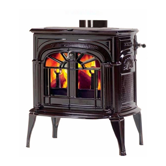
Intrepid
®
Rear Vent Gas Heater
Models:
INDVRCB, INDVREB, INDVRMB, INDVRBS,
INDVRCH, INDVRVG, INDVRBD, INDVRBB,
INDVRCG, INDVRGG, INDVRSG, INDVRBM
Homeowner's Installation
and Operating Manual
INSTALLER: Leave this manual with the appliance.
CONSUMER: Retain this manual for future reference.
Direct Vent,
12761
Intrepid DV Cover
6/07
20012761 7/13 Rev. 13
Advertisement
Table of Contents

Related Manuals for Vermont Castings Intrepid INDVRCB


Summary of Contents for Vermont Castings Intrepid INDVRCB
-
Page 1: Safety Information
INSTALLER / CONSUMER SAFETY INFORMATION PLEASE READ THIS MANUAL BEFORE INSTALLING AND USING APPLIANCE. WARNING! Intrepid Direct Vent, ® IF THE INFORMATION IN THIS MANUAL IS NOT FOLLOWED Rear Vent Gas Heater EXACTLY, A FIRE OR EXPLOSION Models: MAY RESULT CAUSING PROPERTY DAMAGE, PERSONAL INDVRCB, INDVREB, INDVRMB, INDVRBS, INJURY OR LOSS OF LIFE. -
Page 2: Table Of Contents
Table of Contents PLEASE READ THE INSTALLATION & OPERATING INSTRUCTIONS BEFORE USING APPLIANCE. Thank you and congratulations on your purchase of a Vermont Castings stove. IMPORTANT: Read all instructions and warnings carefully before starting installation. Failure to follow these instructions may result in a possible fire hazard and will void the warranty. -
Page 3: Installation
Intrepid® Direct Vent - Rear Vent Gas Heater Installation & Operating Instructions The Intrepid Direct Vent room Heater, Models: INDVRCB, IND- The Intrepid Direct Vent Room Heater, when installed, must be VREB, INDVRMB, INDVRBS, INDVRCH, INDVRVG, INDVRBD, electrically grounded in accordance with local codes or, in the INDVRBB, INDVRCG, INDVRGG, INDVRSG, INDVRBM is a absence of local codes, with the National Electrical Code ANSI/ vented gas appliances listed to ANSI Standard Z21.88-2005 and... -
Page 4: Requirements For The Commonwealth Of Massachusetts
Intrepid® Direct Vent - Rear Vent Gas Heater Installation & Operating Instructions Inspection Requirements for the Commonwealth of Massachusetts The state or local gas inspector of the side wall horizontally vented gas fueled equipment shall not approve the All gas fitting and installation of this heater shall only be installation unless, upon inspection, the inspector observes done by a licensed gas fitter or licensed plumber. -
Page 5: Stove Dimensions
Intrepid® Direct Vent - Rear Vent Gas Heater Stove Dimensions - Intrepid Direct Vent Gas Heater 6 ” ” (165 mm) (418 mm) Valve Inlet ” (347 mm) ” (538 mm) 21 " 24 ” (543 mm) (616 mm) Centerline of Flue Pipe 18”... -
Page 6: Installation Requirements
Intrepid® Direct Vent - Rear Vent Gas Heater Installation Requirements The installation must conform with local codes or, in the absence of local codes, with the National Fuel Gas Code, ANSI Z223.1/NFPA 54 - latest edition. (EXCEPTION: Do not derate this appliance for altitude. Maintain the mani- fold pressure at 3.5 inches w.c. -
Page 7: Minimum Clearances, Parallel Installation, Corner Installation
Intrepid® Direct Vent - Rear Vent Gas Heater Parallel Installation: Minimum Clearance Mantel Clearances and Flue Centerline Combustible Mantel or Trim Max. Vent Materials Length 24” (610 mm) " (476 mm) 2 " (64 mm) Noncombustible 3" (75mm) Min. Materials ST382 A (Max.) B (Min.) -
Page 8: Gas Specifications
Intrepid® Direct Vent - Rear Vent Gas Heater Gas Specifications Horizontal Termination Max. Min. Except for straight-through the wall vent installations. Input Input The vent must rise vertically a minimum of 24” (610 mm) Model Fuel Gas Control BTU/h BTU/h after the first elbow directly off the back of the unit, before INDVR Series Millivolt... -
Page 9: Vertical Termination
Intrepid® Direct Vent - Rear Vent Gas Heater Vertical Termination Restrictor Plate Adjustment for Extended Pipe Runs A vertical vent system must terminate no less than 8’ (2.44 m) and no more than 40’ (12 m) above the appli- This stove is shipped with a restrictor plate in the Parts ance flue collar. -
Page 10: Vent Termination Clearances
Figure 11. • Vermont Castings Group does not require any open- Important: All vent clearances must be maintained. ing for inspection of vent pipe. Check your vent termination clearances against Fig- •... -
Page 11: General Venting Information - Termination Location
2. The special venting system used on Direct Vent Stoves are certified as part of the appliance, with clearances tested and approved by the listing agency. 3. Vermont Castings Group assumes no responsibility for the improper performance of the appliance when the venting system does not meet these requirements. -
Page 12: Termination Clearances
Intrepid® Direct Vent - Rear Vent Gas Heater Termination Clearances Termination clearances for buildings with combustible and noncombustible exteriors. Inside Corner Alcove Applications* Outside Corner Combustible 6" (152 mm) Combustible 6" (152 mm) Noncombustible 2" (51 mm) Noncombustible 2" (51 mm) Balcony - Balcony - with no side wall... -
Page 13: Installation
Intrepid® Direct Vent - Rear Vent Gas Heater Installation Unpack the Stove The stove is shipped fully assembled on its back. Unpack the stove and carefully set it upright. Remove Four (4) Screws CAUTION (Retain for future use) Porcelain enamelled surfaces are fragile. Handle por- celain enamelled castings tenderly. -
Page 14: Venting System Components
Firestop Spacer 46DVA-FS Basic Straight Through-the-Wall Installation Flashing 0/12 - 6/12 46DVA-F6 Horizontal Termination Cap 46DVA-HRC Flashing 6/12 - 12/12 46DVA-F12 Vermont Castings Group Zero Clearance Sleeve (includ- Wall Thimble 46DVA-WT* 54623 Wall Thimble Cover (Brass) 3PVP-TKV Firestop 46DVA-WFS Wall Firestop... -
Page 15: Venting System Assembly, General Information, Options, Planning
Intrepid® Direct Vent - Rear Vent Gas Heater Venting System Assembly Square Horizontal Figure 18 Termination General Information The Intrepid is approved for installation only with the Dura Zero Clearance Wall Sleeve Vent components listed on Page 14. Follow these and the Firestop vent component instructions exactly. -
Page 16: Rear Vent
Intrepid® Direct Vent - Rear Vent Gas Heater Vent Opening - Combustible Wall Vertical High Wind Termination 10" Cap (shown) (254 mm) Storm Collar 10" (254 mm) Roof Flashing Framing Detail Ceiling Firestop Vent Opening - Noncombustible Wall Round Ceil- 7 "... -
Page 17: Horizontal Installation
Intrepid® Direct Vent - Rear Vent Gas Heater 4. Slip the wall cover over the interior end of the horizontal pipe and install into the zero clearance sleeve. Seal the joint inside the wall plate if needed to keep cold air from Figure 25 being drawn into the home. - Page 18 Intrepid® Direct Vent - Rear Vent Gas Heater 2. The location of the horizontal vent termination on an NOTES: exterior wall must meet all local and national building 1. The four (4) wood Figure 29 codes, and must not be easily blocked or obstructed. screws provided Wood...
-
Page 19: Vertical Installation
Intrepid® Direct Vent - Rear Vent Gas Heater When penetrating through stucco wall, install the Figure 32 counter flashing. The counter flashing allows stucco, or other materials, to be finished directly to the sides Wood Screws of the termination cap. First attach the counter flash- ing to the base of the horizontal termination cap with the small screws provided, then mount entire assem- bly onto the wall with the four (4) 2¹⁄₂”... - Page 20 Intrepid® Direct Vent - Rear Vent Gas Heater the top edge of the roof flashing. (Fig. 38) Verify that you semble pipe sections Figure 34 have at least the minimum clearances to combustibles at and elbows as neces- the roofline and in the attic. sary to reach up through the roof line.
-
Page 21: Cathedral Ceiling Installation
Intrepid® Direct Vent - Rear Vent Gas Heater High Wind Vertical Figure 38 Figure 39 Termination Nails Storm Collar Attic Insulation Shield Roof Flashing Required Clearance Optional Low Profile Termination Minimum Clearance Secure Flashing with Non-harden- ing Sealant and Roofing Nails Minimum Clearance ST991... -
Page 22: General Maintenance
Intrepid® Direct Vent - Rear Vent Gas Heater 4. Inspect joints to verify that no pipe sections or fittings Figure 41 have been disturbed or loosened. Also check mechan- ical supports such as wall straps or plumbers tape for rigidity. Supplemental Canadian Instructions When installing DirectVent Pro on appliances in Canada, a 2-piece decorative wall thimble is required in order to... - Page 23 Intrepid® Direct Vent - Rear Vent Gas Heater Two different types of direct vent conversion systems are Use Conversion Kit A (#0931) for described here. One is through an existing factory-built the following chimney: 6” ID Metalbestos metal chimney going through the ceiling. The other is 6”...
- Page 24 Intrepid® Direct Vent - Rear Vent Gas Heater Figure 43 Converting a Factory-Built Metal Chimney Termination Cap Figure 44 Co-Linear Insert Top Adapter 0985K, 0986K or 0987K Vertical Termination Chimney Liner Termination Kit 3” Flex Existing Metal Chimney System 4” Aluminum Flex Pipe Retro Connector Co-Axial to 0909B...
-
Page 25: Converting A Class-A Metal Chimney Or Masonry Chimney To A Direct Vent System
Intrepid® Direct Vent - Rear Vent Gas Heater tory-Built Metal Chimney Figure 46 Figure 45 Converting a Masonry Chimney 1. Remove the existing chimney Adapter cap. Termination 2. Measure the distance from the top end of the chimney to the Top Adapter bottom of the ceiling support Flashing... - Page 26 Intrepid® Direct Vent - Rear Vent Gas Heater Continue to feed the liner Cut & Bend Figure 49 Flashing as Figure 50 out through the opening Needed to Fit in the masonry wall. Chimney Sheet Metal 7. Secure the cap adapter Screws (3) Existing Ceiling to the flashing.
-
Page 27: Connect Gas Supply Line
Intrepid® Direct Vent - Rear Vent Gas Heater Connect the Gas Supply Line Figure 53 Check the rating plate attached by a steel cable to the Retro Connector firebox, to confirm that you have the appropriate firebox for the type of fuel to be used. The Intrepid may be con- verted from one gas to another using the appropriate Fuel Conversion Kit listed on Page 42. -
Page 28: Burner Information
Intrepid® Direct Vent - Rear Vent Gas Heater Burner Information The appliance must only use the gas specified on the rat- ing plate, unless converted using a Vermont Castings Fuel Conversion Kit. Refer to Page 42 for correct Fuel Conver- sion Kit for your stove model. -
Page 29: Install The Log Set
Intrepid® Direct Vent - Rear Vent Gas Heater Install the Log Set Remove the logs from their packaging and inspect each piece for damage. DO NOT INSTALL Rear Log DAMAGED LOGS. Figure 58 CAUTION: Before installation, inspect ember bed burner for damage. Do not use ember bed if damaged or cracked. -
Page 30: Operation
Intrepid® Direct Vent - Rear Vent Gas Heater Top Log Figure 61 Back Log 4. Install top log by mating hole on bottom of log with locating pin on top right side of rear log. (Fig. 61) Left Log Position log so it is angled down toward the area where the front two logs meet. -
Page 31: Flame Characteristics
Intrepid® Direct Vent - Rear Vent Gas Heater Flame Characteristics Turn Turn clockwise counterclockwise It is important to periodically perform a visual check of the to decrease to increase pilot and the burner flames. Compare them to Figure 65. flame height flame height If any of the flames appear abnormal call a service per- son. -
Page 32: Lighting And Operating Instructions
Intrepid® Direct Vent - Rear Vent Gas Heater Lighting and Operating Instructions FOR YOUR SAFETY READ BEFORE LIGHTING WARNING:If you do not follow these instructions exactly, a fire or explosion may result causing property damage, personal injury or loss of life. A. -
Page 33: Troubleshooting
Intrepid® Direct Vent - Rear Vent Gas Heater Troubleshooting the Gas Control System SIT NOVA 820 MILLIVOLT VALVE NOTE: Before trouble shooting the gas control system, be sure external gas shut off is in the “On” position. Possible Causes Symptom Corrective Action 1. -
Page 34: Fuel Conversion Instructions
Intrepid® Direct Vent - Rear Vent Gas Heater 4. Insert a 5/32” Fuel Conversion Instructions or 4 mm Allen wrench into the Figure 68 WARNING! This conversion kit shall be installed Figure hexagonal key- by a qualified service agency in accordance with way of the screw the manufacturer’s instructions and all applicable (Fig. -
Page 35: Gas Conversion
Intrepid® Direct Vent - Rear Vent Gas Heater Pilot Hood Index Marks Pilot Bracket CO105 Fig. 76 Remove pilot hood. (Your pilot may have a different Pilot Assembly appearance.) ST935 Fig. 73 Pilot Assembly location. Pilot • Remove pilot orifice with Allen wrench. (Fig. 75) CO105 Orifice Gas Conversion... - Page 36 Intrepid® Direct Vent - Rear Vent Gas Heater All Models Orifice Bracket 1. Replace burner making sure venturi on bottom of em- ber bed aligns with orifice and is seated properly on air shutter assembly. (Fig. 79) Make sure burner is slid into place at a slight angle and opposite to how it was removed.
-
Page 37: Maintenance
Logs, Pilot and Burner. Use care as the logs are Glass Replacement fragile and susceptible to damage. Replace glass only with Vermont Castings Group approved 6. Replace the glass panel and frame assembly. parts. Refer to Page 40 for Replacement Parts. Refer to 7. -
Page 38: Gasket Replacement
Do not use your stove if the flame pattern differs from that The Intrepid Gas Heater uses a ‘tadpole’ type gasket to shown here. Contact your Vermont Castings dealer or a seal between the glass panel and the frame. In time, this qualified technician for help. -
Page 39: Wiring Diagrams
Intrepid® Direct Vent - Rear Vent Gas Heater Wiring Diagrams POWER CORD On/Off Switch Wiring TP/TH Millivolt Chassis Gas Valve Ground Black ST124b Thermostat (Optional) Thermostat (Optional) Optional Thermostat Wiring FAN JUNCTION BOX St124b on/off/switch wiring Strain Relief 1/11/00 djt ON / OFF TP/TH Rheostat... -
Page 40: Replacement Parts
26 27 32a,b 31a,b Vermont Castings Group reserves the right to make changes in design, materials, specifications, prices and discontinue colors and products at any time, without notice. Intrepid Direct Vent/Rear Vent Gas Heater: Models: INDVRCB, INDVREB, INDVRMB, INDVRBS, INDVRCH, INDVRVG, INDVRBD,... - Page 41 Intrepid® Direct Vent - Rear Vent Gas Heater Intrepid Direct Vent/Rear Vent Gas Heater: (continued) Models: INDVRCB, INDVREB, INDVRMB, INDVRBS, INDVRCH, INDVRVG, INDVRBD, INDVRBB, INDVRCG, INDVRGG, INDVRSG, INDVRBM Ref. Description Intrepid 5. Door Right Refer to Enamel Parts Chart 6. Door Left Refer to Enamel Parts Chart 7.
- Page 42 Intrepid® Direct Vent - Rear Vent Gas Heater Intrepid Direct Vent/Rear Vent Gas Heater: (continued) Models: INDVRCB, INDVREB, INDVRMB, INDVRBS, INDVRCH, INDVRVG, INDVRBD, INDVRBB, INDVRCG, INDVRGG, INDVRSG, INDVRBM Fuel Conversion Kits Conversion Kit, NG to LP Kit #20012921 Conversion Kit, LP to NG Kit #20012910 Shell Enamel Part Numbers - Intrepid Color...
-
Page 43: Optional Accessories
Intrepid® Direct Vent - Rear Vent Gas Heater Optional Accessories Warming Shelf Fan Kits Warming shelves add versatility to your stove; they can be FK20 Fan used to keep foods warm at mealtime. The fan helps distribute heated air from within the firebox Model Color out into the room. - Page 44 Intrepid® Direct Vent - Rear Vent Gas Heater 20012761...
- Page 45 Intrepid® Direct Vent - Rear Vent Gas Heater 20012761...
- Page 46 Intrepid® Direct Vent - Rear Vent Gas Heater 20012761...
-
Page 47: Warranty
Intrepid® Direct Vent - Rear Vent Gas Heater LIMITED LIFETIME WARRANTY PRODUCT COVERED BY THIS WARRANTY All Vermont Castings brand gas stoves, gas inserts, and gas fireplaces installed in the United States of America or Canada. the Limited Lifetime Warranty are not covered, except as provided LIMITED LIFETIME WARRANTY for under the Basic One-Year Warranty. -
Page 48: Energuide
EnerGuide Ratings D.O.E Model Fireplace Efficiency (%) (AFUE%) INDVR 68.0 76.5 Recherchez dans la brochure les caractéristique de rendement énergétique de foyer au gaz Énerguide Based on CSA P.4.1-09 Selon CSA P.4.1-09 Vermont Castings Group 149 Cleveland Drive • Paris, Kentucky 40361 www.vermontcastingsgroup.com...
Need help?
Do you have a question about the Intrepid INDVRCB and is the answer not in the manual?
Questions and answers