
Subscribe to Our Youtube Channel
Related Manuals for GeoVision GV-POE1601


Summary of Contents for GeoVision GV-POE1601
- Page 1 GV-PoE Switch Multicam Digital GV-POE1601 User's Manual Before attempting to connect or operate this product, POE1601-B please read these instructions carefully and save this manual for future use.
- Page 2 Every effort has been made to ensure that the information in this manual is accurate. GeoVision, Inc. makes no expressed or implied warranty of any kind and assumes no responsibility for errors or omissions. No liability is assumed for incidental or consequential damages arising from the use of the information or products contained herein.
-
Page 3: Table Of Contents
Contents Safety Precautions ................... 1 Introduction....................... 2 Hardware Description ..................5 Preparation for Web Configuration ..............8 User Login....................... 10 Administrator ....................11 Port Management ................... 17 VLAN Setting....................22 Per Port Counter..................... 27 10. QoS Setting ..................... 28 11. Security ......................31 12. -
Page 4: Safety Precautions
1. Safety Precautions FCC Warning This Equipment has been tested and found to comply with the limits for a Class-A digital device, pursuant to Part 15 of the FCC rules. These limits are designed to provide reasonable protection against harmful interference in a residential installation. This equipment generates, uses, and can radiate radio frequency energy. -
Page 5: Introduction
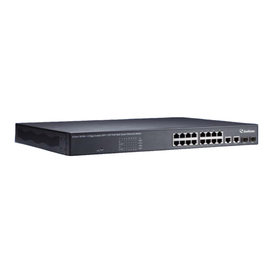
2. Introduction Product Overview The switch is a 16-port 10/100BaseTX with RJ-45 Connectors, PoE+ plus 2-port Gigabit Copper/SFP Combo Uplink Port Rack-mount Web Smart PoE Switch. The switch supports IEEE 802.3at Power over Ethernet standard, maximum 250 W power consumption per system and no special network cable required for connecting your powered devices (PD), such as IP cameras. - Page 6 Introduction Port Counter (Statistic): Monitor the port statistic VLAN Setting VLAN Mode: Port-based and Tag-based VLAN Port Based VLAN: Up to 10 ports Port-Based VLAN Tag Based VLAN: Up to 32 VLANs, Available VID from 1~4094 QoS Setting Support High & Low Priority Queue Priority Mode: First-In-First-Out, Strict and Weight-Round-Robin (WRR) Priority Mode Class of Service schemes: 802.1p, IP TOS / DS or Port Base...
- Page 7 Before you start to install this switch, verify your package that contains the following items: 1. GV-POE1601 x 1 2. AC Power Cord x 1 3. Screw x 8 4. Rack Mount Kit x 1 5. User’s Manual CD x 1 6. GV-POE1601 Quick Start Guide x 1 ...
-
Page 8: Hardware Description
Hardware Description 3. Hardware Description This section mainly describes the hardware of the 16 PoE port Ethernet Combo Web-Smart Switch and gives a physical and functional overview on the certain switch. Product Overview Front Ethernet Ports The front panel of the web smart switch consists of 16 10/100M BaseTX RJ-45 ports and 2 combo Gigabit uplink RJ-45 / SFP ports. - Page 9 RJ-45 Fast LED Display Ethernet Reset Button RJ-45 Port Gigabit Ethernet Port Gigabit SFP Port Rear Panel The 3-pronged power plug is placed at the rear panel of the switch right side shown as below. LED Indicators The LED Indicators present real-time information of systematic operation status.
- Page 10 Hardware Description AC Power Input Connect the attached power cord to the AC power input connector; the available AC power input is range from 100-240 VAC. Ethernet cable Request The wiring cable types are as below. 10BaseT: 2-pair UTP/STP Cat. 3, 4, 5 cable, EIA / TIA-568 100-ohm (Max. 100 m) 100BaseTX: 2-pair UTP/STP Cat.
-
Page 11: Preparation For Web Configuration
4. Preparation for Web Configuration The web management page allows you to use a standard web-browser such as Microsoft Internet Explorer, Google Chrome or Mozilla Firefox, to configure and interrogate the switch from anywhere on the network. Before you attempt to use the web user interface to manage switch operation, verify that your switch is properly installed on your network and that every PC on this network can access the switch via the web browser. - Page 12 Preparation for Web Configuration Launch the web browser and Login. 1. Launch the web browser (Internet Explorer or Mozilla Firefox) on the PC. 2. Type http://192.168.0.250 (or the IP address of the switch). And then press Enter. 3. The login screen will appear next. 4.
-
Page 13: User Login
5. User Login This part instructs users how to set up and manage the switch through the web user interface. Follow the description to understand the procedure. At first, open the web browser, type http://192.168.0.250 and then the users will see the login page. -
Page 14: Administrator
Administrator 6. Administrator Authentication Configuration This page shows authentication configuration information. Users can set new Username and Password in this page. Figure 6-1 System IP Configuration This page shows system configuration including the current IP address and sub-net mask and gateway. - Page 15 Users can configure the IP settings, Subnet Mask, Gateway as below: IP address: Manually assign the IP address that the network is using. The default IP is 192.168.0.250. Subnet Mask: Assign the subnet mask to the IP address. The default Subnet Mask is 255.255.255.0.
- Page 16 Administrator System Status This page displays the information about the switch of MAC address, how many ports it has, system version and. Besides, users can also fill in up to 15 characters in the Comment, Contact and Location field for note. Figure 6-3 ...
- Page 17 Load Default Setting Clicking the Load button will make the switch being set to the original configuration. Figure 6-5 Note: Loading default from the web interface does not include user name, password and IP configuration. If you want to restore default settings including IP, user name and password, you can press the Reset button on the front panel of the switch.
- Page 18 Administrator Firmware Update Before the firmware update procedure is executed, you should enter the password twice and then press Update button. Figure 6-6 The popup warning window appears for making sure you want to proceed the firmware upgrading process. The flash memory will be erased, and all functions will be disabled temporarily except the firmware update itself.
- Page 19 The below screen shows the Uploading process is starting. Figure 6-9 After firmware is correctly uploaded, the web page shows OK.. Click Continue to re-login the switch. Figure 6-10 Reboot Device Click Confirm button to restart the switch.. Figure 6-11 ...
-
Page 20: Port Management
Port Management 7. Port Management Port Management includes Port Configuration, Port Mirroring, Bandwidth Control, Broadcast Storm Control and PoE. Port Configuration In Port Configuration, you can set and view the operation mode for each port. Figure 7-1 Function: ... - Page 21 Select Port No.: Select the port/ports you want to apply to. You can select one or multiple ports here. Click Update to have the configuration take effect. Port Mirroring The Port mirroring is a method for monitoring traffic in switched networks. That Traffic through ports can be monitored by any of the ports means traffic goes in or out monitored (source) ports will be duplicated into mirroring (destination) port.
- Page 22 Port Management Bandwidth Control This page allows the setting of the bandwidth for each port. The TX rate and RX rate can be filled with the number ranging from 1 to 255. This number should be multiplied by the selected bandwidth resolution to get the actual bandwidth.
- Page 23 Broadcast Storm Control The switch implements a broadcast storm control mechanism. Tick the check boxes to have them beginning to drop incoming broadcast packets if the received broadcast packet counts reach the threshold defined. Each port’s broadcast storm protection function can be enabled individually by ticking the check boxes.
- Page 24 Port Management Users could know per PoE port out power status in this page and also enable or disable per port. Figure 7-6 Port: The port number. Enable: Enable PoE feature of the specific ports. Output Power: The output power of the port.
-
Page 25: Vlan Setting
8. VLAN Setting A Virtual LAN (VLAN) is a logical network grouping that limits the broadcast domain, which would allow you to isolate network traffic, so only the members of the same VLAN will receive traffic from the ones of the same VLAN. Basically, creating a VLAN from a switch is logically equivalent of reconnecting a group of network devices to another Layer 2 switch. - Page 26 VLAN Setting VLAN Mode: Displays VLAN mode: port based / Tag based VLAN. Here you can also switch back to Port Based VLAN Mode. Tag Mode: Add tag means the outgoing packet of the selected port will be inserted a 802.1Q tag.
- Page 27 VLAN Member in Tag Based Mode In Tag Based Mode you need to define and configure your VLAN groups. Assign the VLAN ID, select the VLAN member ports, assign the PVID and check the configuration result. Figure 8-4 ...
- Page 28 VLAN Setting VLAN Member Port Select: Select the VLAN Member here. Figure 8-6 VID Source Port: This table allows you to configure PVID of the port. Select the port number while you add VLAN and select VLAN member ports, the selected ports' PVID will be the VID you typed. Note: One port only can have one PVID.
- Page 29 Configuration Steps: First, add your VLAN Groups (identified throughout your network by unique and constant numbers). Start with IDs from 100 and up is often. Starting with 100 gives you enough free room and less compatibility issues. Second, enter “100”...
-
Page 30: Per Port Counter
Per Port Counter 9. Per Port Counter Port Counter This page provides port counter of each port. There are 4 categories: Receive Packet & Transmit Packet / Transmit & Collision / Receive Packet & Drop / Receive & CRC error. Once you change the counter category, the counter will be cleared automatically. -
Page 31: Qos Setting
10. QoS Setting Here you can configure QoS policy priority mode and CoS (Class of Service) configuration. QoS (Quality of Service) refers to mechanisms in the network software that make the actual determination of which packets have priority. CoS refers to feature sets, or groups of services, that are assigned to users based on company policy. - Page 32 QoS Setting Port, 802.1p, IP / DS based The page allows you to enable Port Based, VLAN Tag or IP/DS mode of COS. Figure 10-2 Class of Service Configuration Enable High Priority: After Enabled High Priority, the following enabled Port Based parameter will become High Priority.
- Page 33 TCP / UDP Port Based This page allows users to define the Option type of the pre-defined protocols or user-defined protocols. Select the Option of the Protocol as below figure shown. Figure 10-3 The Class of Service for TCP/UDP port number allows the network administrator to assign the specific application to a priority queue.
-
Page 34: Security
Security 11. Security The Security feature allows you to enable Port Security (MAC Address Binding) and TCP_UDP Filter feature. MAC Address Binding This is also known as Port Security function of some other switch. The feature allows you to bind 1-3 MAC address to one physical port. - Page 35 TCP / UDP Filter Figure 11-2 Function Enable: To Enable or Disable the function. Port Filtering Rule: The outgoing packet with selected protocol will be either forwarded or dropped at secure WAN port as the figure shown below. ...
-
Page 36: Spanning Tree
Spanning Tree 12. Spanning Tree The switch supports IEEE 802.1D-2004 STP protocol, the RSTP protocol can backward compatible to legacy Spanning Tree Protocol (STP) and 802.1w Rapid Spanning Tree Protocol (RSTP). STP Bridge Settings Figure 12-1 STP Mode: Disable, STP and RSTP. Select the STP version you want to enable. ... - Page 37 STP Port Settings The STP Port Setting page allows you to change the port priority and its path cost. After STP/RSTP is enabled, the system automatically assigns the port priority and path cost to the port. Normally, it is necessary to change the parameters, however, you may need to control the root switch or block port in some condition.
- Page 38 Spanning Tree Loopback Detection Settings In some condition, the users may incorrectly connect the wrong cable and lead the port loop. The Loopback Detection feature can help you leave the risk. Figure 12-3 Loopback Detection Function: This column allows you to enable or disable Loopback Detection function.
-
Page 39: Trunking
13. Trunking Port trunk allows multiple links to be bundled together and act as a single physical link for increased throughput. It provides load balancing, and redundancy of links in a switched inter-network. Actually, the link does not have an inherent total bandwidth equal to the sum of its component physical links. - Page 40 Trunking System Priority: This column allows you to configure the system priority for LACP. Set a value between 1 and 65535. The default value is 1. The higher the number, the lower the priority. The system priority controls which links between LACP partner switches are active and determines the standby status of the links for each LACP port channel.
-
Page 41: Backup / Recovery
14. Backup / Recovery This function provides the users with a method to backup / recovery the switch configuration. The users can save configuration file to a specified file. If the users want to recover the original configuration, which is saved at the specified path, just enter the password and then press the upload button. -
Page 42: Miscellaneous
Miscellaneous 15. Miscellaneous Miscellaneous setting is used to configure output queue aging time, VLAN stride and IGMP snooping. Figure 15-1 Output Queue Aging Time: Purpose: This function is used to avoid the traffic jam on one port will not cause the congestion of other ports. - Page 43 VLAN Striding: Purpose: For some network environment, the network administrator probably wanst to filter undesired broadcast or multicast packet to enhance the network bandwidth utilization and forward meaningful unicast to a specific destination. VLAN is a good mechanism to block broadcast packet, but it can also block the unicast packet communication between VLANs.
- Page 44 Miscellaneous VLAN Uplink Setting: If VLAN uplink function is enabled and the destination port of an unicast packet is located at the next VLAN, this packet will be forwarded to the uplink port. Choose the Uplink Port X for the port ID. The Uplink X will be the uplink port of its VLAN.
-
Page 45: Logout
16. Logout The administrator has write access for all parameters governing the onboard agent. Users should therefore assign a new administrator password as soon as possible, and store it in a safe place. After finished configuring the switch, you can click Logout to leave the configuration page. Figure 16-1 ... -
Page 46: Restoring Default Settings
Restoring Default Settings 17. Restoring Default Settings Follow the steps below to restore the switch to its default settings using the Reset button on the front panel of the switch. Note: After restoring default settings, you will need to configure IP address, ID and Password again. -
Page 47: Specifications
18. Specifications Ports 18 ports Number of Ports 16‐port 10/100BaseTX with RJ‐45 Connectors, PoE+ 2‐port Gigabit Copper/SFP Combo Uplink Port Performance MAC Address 4 K Buffer Memory 2.75 M bits Transmission Method Store and Forward 10/100BaseTX Cat. 5 UTP/STP Transmission Media 1000BaseT Cat. 5 / Cat. 5E UTP/STP 10 Mbps port ‐ 14,880 pps Filtering/Forwarding Rates 100 Mbps port ‐ 148,800 pps 1000 Mbps port ‐ 1,488,000 pps Smart Features Port Based VLAN 18 Tagged Based VLAN 32, VID = 1~4094 IGMP Snooping V1 & V2 Link Aggregation 1, Gigabit ports Quality of Service (QoS) High & Low priority queues, 802.1p Security Port & MAC binding, 3 MAC per port Port State, Speed/Duplex, Flow Control Configuration, Port Mirroring, Bandwidth Control, Port Management ...
Need help?
Do you have a question about the GV-POE1601 and is the answer not in the manual?
Questions and answers