
Subscribe to Our Youtube Channel
Related Manuals for GeoVision GV-POE0410-E-V2


Summary of Contents for GeoVision GV-POE0410-E-V2
- Page 1 GV-PoE Switch GV-POE0410-E-V2 User's Manual Before attempting to connect or operate this product, please read these instructions carefully and save this manual for future use. POE0410EV2-A...
- Page 2 GeoVision. Every effort has been made to ensure that the information in this manual is accurate. GeoVision, Inc. makes no expressed or implied warranty of any kind and assumes no responsibility for errors or omissions. No liability is assumed for incidental or consequential damages arising from the use of the information or products contained herein.
-
Page 3: Table Of Contents
Contents Safety Precautions................... ii 1. Introduction....................1 1.1. Key Features ...................2 1.2. Packing List ..................2 1.3. Options ....................3 2. Hardware Description................4 3. DIN-Rail Mounting ..................7 4. Hardware Installation.................8 4.1. Wiring the DC Power Inputs.............8 4.2. Wiring the Alarm Relay ..............9 4.3. -
Page 4: Safety Precautions
Safety Precautions FCC Warning This Equipment has been tested and found to comply with the limits for a Class-A digital device, pursuant to Part 15 of the FCC rules. These limits are designed to provide reasonable protection against harmful interference in a residential installation. -
Page 5: Introduction
1. Introduction Product Overview GV-POE0410-E-V2 is a 4-port PoE Switch with 4 PoE+ 10/100/1000 BaseT(X) port and 2 Gigabit SFP. The switch supports IEEE 802.3at Power over Ethernet standard with up to 30 W per port, with a maximum power consumption of 127 W. -
Page 6: Key Features
Extreme temperature tolerance (-40 °C ~ 75 °C / -40 °F ~ 167 °F) • Auto-MDI/MDI-X • Auto-Negotiation • Alarm control • DIN-Rail Installation • Redundant DC power • 6 kV surge protection • Up to 4 GV-IP Cameras support 1.2. Packing List 1. GV-POE0410-E-V2 2. GV-POE0410-E-V2 Quick Installation Guide... -
Page 7: Options
1.3. Options Optional devices can expand the capability and versatility of GV-POE0410-E-V2. Contact your dealer for more information. The SFP Transceiver is designed to plug into the SFP port of the GV-POE Switch and is the interface between the switch and optical fiber cables. This product complies GV-LC and GV-LC10 with IEEE 802.3z 1000Base SX/LX standards. -
Page 8: Hardware Description
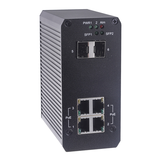
2. Hardware Description This section mainly describes the hardware of this switch and provides its physical and functional overview. Dimensions The dimensions of this switch are 120 x 55 x 108 mm (4.72” x 2.16” x 4.23”). - Page 9 Front Panel Power 1 & 2 Alarm Control LED 2 Gigabit SFP ports / LED 4 PoE ports / LED Status Description PWR1 Green on Power on Power off PWR2 Green on Power on Power off Red on Port link down or power failure No event Port 1~4 Green On...
- Page 10 Terminal Block Alarm Control The GV-POE0410-E-V2 is featured with a redundant power supply for automatic power backup and supports alarms alerting for power and connection failure. Power Supply With DC power cables wired to both PW1 and PW2 on the terminal block, one of the power supplies provides backup power to be automatically switched to when the other fails.
-
Page 11: Din-Rail Mounting
3. DIN-Rail Mounting A DIN-Rail clip is built into the rear body of the switch supporting EN 50022 standard DIN Rail. The dimensions of EN 50022 DIN Rail are included in the following diagram. Follow the steps below to mount the switch onto a DIN-Rail track. -
Page 12: Hardware Installation
4. Hardware Installation 4.1. Wiring the DC Power Inputs Before installing the power input, be sure the DC Power Supply is compliant with the standard power supply certification. The suggested power output voltage you can choose for IEEE 802.3af compliant PD is 48 V/DC, and 50 ~ 57 V/DC for IEEE 802.3at compliant PD. -
Page 13: Wiring The Alarm Relay
4.2. Wiring the Alarm Relay The switch provides one dry relay output for power or port link event. The alarm relay is “open” by default and forms a close circuit upon event occurrence. The relay conductor has a maximum capability of 24 W. When it connects with a DC 24 V power source, the maximum current supported is 1 A. -
Page 14: Enable The Event Alarm Function
4.4. Enable the Event Alarm Function The switch is equipped with one dry relay alarm output for alerting upon port link and/or power failures. This session introduces how to enable the event alarm DIP switch upon such events. The new configuration is activated immediately without system reset whenever the DIP SWITCH has been changed. -
Page 15: Cabling
4.5. Cabling UTP/STP cables are required for Port 1~4. Fiber transceiver is required for Port 5 & 6 (SFP). thernet cable Request The wiring cable types for da ta transmission are as below. 10/100 BaseT(X) Cat. 5 UTP/STP 1000 BaseT Cat. 5e, 6 UTP/STP The wiring cable types for data transmissi on and power delivery in any speed are Cat.
Need help?
Do you have a question about the GV-POE0410-E-V2 and is the answer not in the manual?
Questions and answers