
Subscribe to Our Youtube Channel
Related Manuals for GeoVision GV-POE0811-V2


Summary of Contents for GeoVision GV-POE0811-V2
- Page 1 GV-PoE Switch GV-POE0811-V2 User's Manual Before attempting to connect or operate this product, please read these instructions carefully and save this manual for future use. POE0811V2-A...
- Page 2 Every effort has been made to ensure that the information in this manual is accurate. GeoVision, Inc. makes no expressed or implied warranty of any kind and assumes no responsibility for errors or omissions. No liability is assumed for incidental or consequential damages arising from the use of the information or products contained herein.
-
Page 3: Table Of Contents
Contents 1. Safety Precautions..................... 1 2. Introduction ......................2 2.1 Product Overview ..................2 2.2 Key Features ..................... 2 2.3 Package Contents ..................4 2.4 Options ...................... 5 3. Hardware Description ..................6 4. Preparation for Web Configuration ..............9 5. -
Page 4: Safety Precautions
1. Safety Precautions FCC Warning This Equipment has been tested and found to comply with the limits for a Class-A digital device, pursuant to Part 15 of the FCC rules. These limits are designed to provide reasonable protection against harmful interference in a residential installation. This equipment generates, uses, and can radiate radio frequency energy. -
Page 5: Introduction
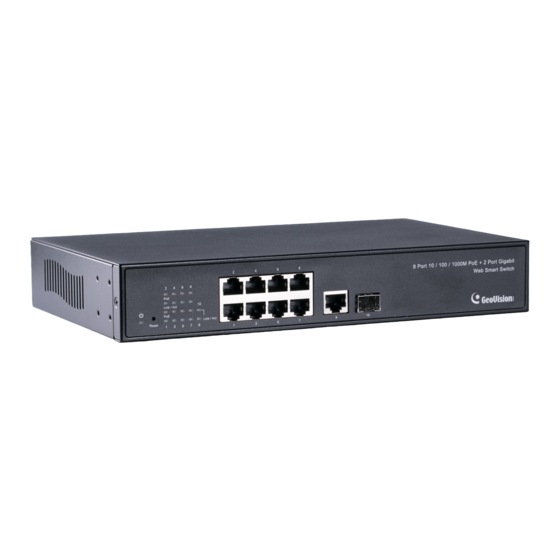
2. Introduction 2.1 Product Overview The GV-POE0811-V2 is an 8-port 10/100/1000BaseT(X) Ports + 2-port Gigabit uplink (1 x RJ-45 + 1 x SFP) Desktop Web Managed PoE Switch. The switch supports IEEE 802.3at Power over Ethernet standard and maximum 130W power consumption per system and no special network cable required for your powered devices (PD), such as IP cameras. - Page 6 Introduction Port Counter (Statistic): Monitor the port statistic VLAN Setting VLAN Mode: Port-based and Tag-based VLAN Port Based VLAN: 16 ports Tag Based VLAN: Up to 16 VLANs, Available VID from 1~4094 QoS Setting ...
-
Page 7: Package Contents
Before you start to install this switch, verify your package that contains the following items: 1. GV-POE0811-V2 x 1 2. AC Power Cord x 1 3. Rack Mount Kit x 1 + Screw x 8 4. User’s Manual CD x 1 5. GV-POE0811-V2 Installation Guide x 1 ... -
Page 8: Options
Introduction 2.4 Options Optional devices can expand your GV-POE0811-V2’s capabilities and versatility. Contact your dealer for more information. The SFP Transceiver is designed to plug into the SFP port of the GV-POE Switch and is the interface between the switch and optical fiber cables. -
Page 9: Hardware Description
3. Hardware Description This section gives a physical and functional overview on the 8-Port Gigabit Ethernet with 2-Port Open Slots Gigabit SFP Web Management Switch. Product Overview Front Ethernet Ports The front panel of this switch consists of 8 10/100/1000 Base-TX RJ-45 ports, 1 Gigabit SFP Uplink port, and 1 10/100/1000 Base RJ-45 Uplink port. -
Page 10: Reset Button
Hardware Description Reset Button The button allows you to restore the configuration to default. For details see 10. Restoring Default Settings later in this manual. Rear Panel The 3-pronged power plug is placed at the rear panel of the switch right side shown as below. ... - Page 11 Ethernet Cable Request The wiring cable types are as below. 10/100BaseT(X): 2-pair UTP/STP Cat. 5 cable, EIA / TIA-568 100-ohm (Max. 100 m) 1000BaseT: 4-pair UTP/STP Cat. 5e, 6 cable, EIA / TIA-568 100-ohm (Max. 100 m) PoE: To deliver power without problem, the Cat 5 / 5e and Cat 6 cable is suggested.
-
Page 12: Preparation For Web Configuration
Preparation for Web Configuration 4. Preparation for Web Configuration The Web management page allows you to use a standard Web-browser such as Microsoft Internet Explorer, Google Chrome or Mozilla Firefox, to configure and interrogate the switch from anywhere on the network. Before using the Web user interface to manage switch operation, verify that your switch is properly installed on your network and that every PC on this network can access the switch via the Web browser. - Page 13 Launch the Web browser and Login 1. Launch the Web browser (Internet Explorer, Mozilla Firefox or Google Chrome) on the 2. Type http://192.168.0.250 (or the IP address of the switch). And then press Enter. 3. The login screen will appear next. 4.
-
Page 14: User Login
Configuration 5. User Login This part instructs users how to set up and manage the switch through the Web user interface. Follow the description to understand the procedure. At first, open the Web browser, type http://192.168.0.250 and then the users will see the login page. -
Page 15: Configuration
6. Configuration 6.1 System Figure 6-1 The System Configuration page displays the following information: MAC Address: Displays the unique hardware address assigned by manufacturer (default). S/W Version: Displays the switch’s firmware version. H/W Version: Displays the switch’s Hardware version. ... - Page 16 Configuration DHCP Enabled: Click to enable the switch to act as the DHCP Client, and the switch will try getting the IP Address from the DHCP server. Fallback IP address: Manually assign the IP address that the network is using. The default IP is 192.168.0.250.
-
Page 17: Ports
6.2 Ports In Port Configuration, you can set and view the operation mode for each port. Figure 6-2 Enable Jumbo Frames: This switch provides more efficient throughput for large sequential data transfers by supporting jumbo frames on Gigabit Ethernet ports up to 9216 bytes. -
Page 18: Port Configuration
Configuration Port Configuration Mode: Set the port speed as Auto, 10 half, 10 Full, 100 Half, 100 Full, 1000 Full or Disabled. Flow Control: Enable the automatic management of transmission speed. Drop frames after excessive collisions: Enable the switch to drop frames when excessive collisions occur in half-duplex mode. -
Page 19: Vlans
6.3 VLANs A Virtual LAN (VLAN) is a logical network grouping that limits the broadcast domain, which would allow you to isolate network traffic, so only the members of the same VLAN will receive traffic from the ones of the same VLAN. Basically, creating a VLAN from a switch is logically equivalent of reconnecting a group of network devices to another Layer 2 switch. - Page 20 Monitoring Figure 6-5 [VLAN Configuration List] Lists all the current VLAN groups created for this system. Up to 16 VLAN groups can be defined. VLAN 1 is the default untagged VLAN. Modify: Press this button to modify the VLAN member port of the selected VLAN. ...
-
Page 21: Aggregation
6.4 Aggregation Port trunk allows multiple links to be bundled together and act as a single physical link for increased throughput. It provides load balancing, and redundancy of links in a switched inter-network. Actually, the link does not have an inherent total bandwidth equal to the sum of its component physical links. - Page 22 Monitoring Figure 6-8 IGMP Enabled: When enabled, the switch will monitor network traffic to determine which hosts want to receive multicast traffic. Router Ports: Set if ports are connecting to the IGMP administrative routers. Unregistered IPMC Flooding enabled: Set the forwarding mode for unregistered (not-joined) IP multicast traffic.
-
Page 23: Mirroring
6.6 Mirroring Port Mirroring is used on a network switch to send a copy of network packets seen on one switch port (or an entire VLAN) to a network monitoring connection on another switch port. This is commonly used for network appliances that require monitoring of network traffic, such as an intrusion-detection system. -
Page 24: Lldp
Monitoring 6.7 LLDP The Link Layer Discovery Protocol (LLDP) allows stations attached to an IEEE 802 LAN to advertise, to other stations attached to the same IEEE 802 LAN, the major capabilities provided by the system incorporating that station, the management address or addresses of the entity or entities that provide management of those capabilities, and the identification of the stations point of attachment to the IEEE 802 LAN required by those management entity or entities. - Page 25 Figure 6-11 Tx Interval: The switch periodically transmits LLDP frames to its neighbours for having the network discovery information up-to-date. The interval between each LLDP frame is determined by the Tx Interval value. Tx Hold: Each LLDP frame contains information about how long the information in the LLDP frame shall be considered valid.
-
Page 26: Lldp State
Monitoring 6.8 LLDP State Figure 6-12 Select LLDP mode here. The modes here available here include: Rx and Tx: The switch will send out LLDP information, and will analyze LLDP information received from neighbours. Rx only: The switch will not send out LLDP information, but LLDP information from neighbour units is analyzed. -
Page 27: Quality Of Service
6.9 Quality of Service In QoS Mode, select QoS Disabled, 802.1p or DSCP, and click Apply to configure the related parameters. Figure 6-13 802.1p Configuration] Packets are prioritized using the 802.1p field in the VLAN tag. Figure 6-14 Prioritize Traffic: Allows the customization of 802.1p to Traffic classifiers to quickly set ... - Page 28 Monitoring [DSCP Configuration] Packets are prioritized using the DSCP (Differentiated Services Code Point) value. Figure 6-15 Prioritize Traffic: Allows the customization of DSCP to Traffic classifiers to quickly set the values in the DSCP Configuration table to a common priority queue. Select Custom if you want to set each value individually.
-
Page 29: Power Over Ethernet
6.10 Power over Ethernet PoE technology is a system to pass electrical power safely, along with data, on Ethernet cabling. Power is supplied in common mode over two or more of the differential pairs of sires found in the Ethernet cables and comes from a power supply within a PoE enabled networking devise such as Switch or can be injected into a cable run with a mid-span power supply. -
Page 30: Monitoring
Monitoring 7. Monitoring 7.1 Statistics Overview User can mirror traffic from any source port to a target port for real-time analysis the following figures shows clearly the statistics overview. Click Clear to renew the details collected and displayed. Click Refresh to reset the details displayed. Figure 7-1 ... -
Page 31: Igmp Status
7.3 IGMP Status IGMP Status shows the IGMP Snooping statistics for the whole switch. Figure 7-3 VLAN ID: VLAN ID number. Querier: Shows whether Querying is enabled. Queries transmitted: Shows the number of transmitted Query packets. ... -
Page 32: Lldp Statistics
Monitoring 7.4 LLDP Statistics Figure 7-4 Tx Frames: The number of LLDP frames transmitted on the port. Rx Frames: The number of LLDP frames received on the port. Rx Error: The number of received LLDP frames containing some kind of error. ... -
Page 33: Lldp Table
7.5 LLDP Table Figure 7-5 Local Port: The port on which the LLDP frame was received. Chassis ID: The Chassis ID is the identification of the neighbor's LLDP frames. Remote Port ID: The Remote Port ID is the identification of the neighbor port. ... - Page 34 Monitoring 7.6 Ping This command sends ICMP echo request packets to another node on the network. Figure 7-6 [Ping Parameters] Target IP Address: Type the IP address of the host. Count: Set the number of packets to send. ...
-
Page 35: Maintenance
8. Maintenance 8.1 Warm Restart Press Yes to restart the switch. The reset will be complete when the power light stops blinking. Figure 8-1 8.2 Factory Default To restore the switch to the default settings, select Factory Default from the left menu and click Yes. -
Page 36: Software Upload
Maintenance 8.3 Software Upload To upgrade the firmware version of the switch, follow the steps below: 1. Click Browse to select the firmware file and click Upload. Figure 8-3 2. After the uploading process is completed, this message appears. Click Yes to activate the new software. -
Page 37: Logout
9. Logout The administrator has write access for all parameters governing the onboard agent. The user should therefore assign a new administrator password as soon as possible, and store it in a safe place. After finishing configuring the switch, you can click Logout to leave the configuration page. Figure 9-1 ... -
Page 38: Restoring Default Settings
Logout 10. Restoring Default Settings You can load the default value with the Reset button or with the Web interface. Hardware To restore the switch to its default settings using the Reset button, follow the steps below: 1. Turn on the switch. 2. -
Page 39: Specifications
11. Specifications Ports 10 ports, including: 8‐port 10/100/1000BaseT(X) with RJ‐45 Connectors, PoE+ Number of Ports 1‐port Gigabit SFP Uplink Slot 1‐port Gigabit RJ‐45 Uplink Port Performance MAC Address 8 K Buffer Memory 4 M bits Jumbo Frames 9.6 KB Transmission Method Store and Forward 10/100BaseT(X) Cat. 5 UTP/STP Transmission Media 1000BaseT Cat. 5e, 6 UTP/STP 10 Mbps port ‐ 14,880 pps Filtering/Forwarding Rates 100 Mbps port ‐ 148,800 pps 1000 Mbps port ‐ 1,488,000 pps Backplane Capacity 20 Gbps Smart Features Port Based VLAN 16 Tag Based VLAN 16, VID 1~4094 IGMP Snooping V1 & V2 Link Aggregation up to 8 groups ...
Need help?
Do you have a question about the GV-POE0811-V2 and is the answer not in the manual?
Questions and answers