
Related Manuals for GeoVision GV-POE0410-E


Summary of Contents for GeoVision GV-POE0410-E
- Page 1 GV-PoE Switch GV-POE0410-E User's Manual Before attempting to connect or operate this product, please read these instructions carefully and save this manual for future use. POE0410E-B...
- Page 2 GeoVision. Every effort has been made to ensure that the information in this manual is accurate. GeoVision, Inc. makes no expressed or implied warranty of any kind and assumes no responsibility for errors or omissions. No liability is assumed for incidental or consequential damages arising from the use of the information or products contained herein.
-
Page 3: Table Of Contents
Contents Contents........................2 1. Safety Precautions ....................1 2. Introduction ......................2.1. Key Features ..................2.2. Packing List ..................3 2.3. Option ....................3. Hardware Description.................... 4. DIN-Rail Mounting ....................5. Hardware Installation..................... 5.1. Wiring the DC Power Inputs ..............5.2. -
Page 4: Safety Precautions
1. Safety Precautions FCC Warning This Equipment has been tested and found to comply with the limits for a Class-A digital device, pursuant to Part 15 of the FCC rules. These limits are designed to provide reasonable protection against harmful interference in a residential installation. -
Page 5: Contents
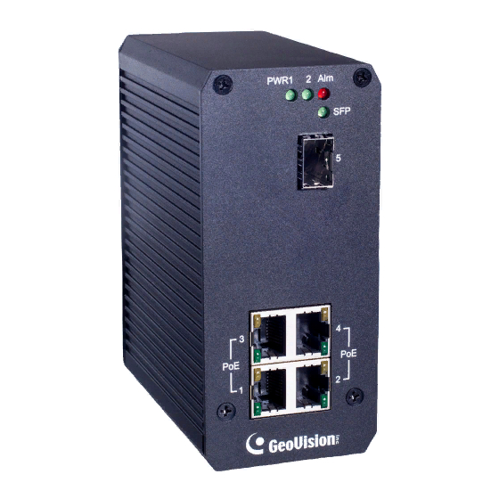
Figure 2-1 Product Overview The GV-POE0410-E is a 4-port PoE Switch with 4 PoE+ 10/100/1000BaseT(X) port and 1 Gigabit SFP. The switch supports IEEE 802.3at Power over Ethernet standard with up to 30 W per port and maximum 130 W power consumption per system. No special network cable is required for connecting your powered devices (PD), such as IP cameras. -
Page 6: Key Features
1. GV-POE0410-E x 1 2. GV-POE0410-E Quick Start Guide x 1 2.3. Option Optional devices can expand your GV-POE0410-E’s capabilities and versatility. Contact your dealer for more information. The SFP Transceiver is designed to plug into the SFP port of the GV-POE Switch and is the interface between the switch and optical fiber cables. -
Page 7: Hardware Description
3. Hardware Description This section mainly describes the hardware of this switch and gives a physical and functional overview on the switch. Dimensions The dimensions of this switch are 120 x 55 x 108 mm (4.72” x 2.16” x 4.25”). Figure 3-1 4 ... - Page 8 Front Panel Power 1 ~ 2 Alarm Control / LED Gigabit SFP port / LED 4 PoE ports / LED Figure 3-2 Status Description PWR1 Green on Power on Power off PWR2 Green on Power on Power off Red on Port link down or power failure No event Port 1~4...
- Page 9 Terminal Block Alarm Control Figure 3-3 The GV-POE0410-E is featured with a redundant power supply for automatic power backup and supports alarms alerting for power and link failure. Power Supply With DC power cables wired to both PW1 and PW2 on the terminal block, one of the power supplies provides backup power immediately if the other fails.
-
Page 10: Din-Rail Mounting
4. DIN-Rail Mounting A DIN-Rail clip is built in the rear body of the switch supporting EN 50022 standard DIN Rail. The dimensions of EN 50022 DIN Rail are included in the following diagram. Follow the steps below to mount the switch on a DIN-Rail track. Insert the upper end of the DIN-Rail clip into the back of the DIN-Rail track from its upper side Lightly push the bottom of the DIN-Rail clip into the track. -
Page 11: Hardware Installation
5. Hardware Installation 5.1. Wiring the DC Power Inputs Before installing the power input, be sure the DC Power Supply is compliance with standard power supply certification. The suggested power output voltage you can choose for the IEEE 802.3af compliant PD is 45 ~ 57 V/DC, and 50 ~ 57 V/DC for the IEEE 802.3at compliant PD. -
Page 12: Wiring The Alarm Relay
Diagram of power input wiring Figure 5-2 5.2. Wiring the Alarm Relay The switch provides one dry relay output for power or port link event. The alarm relay default is “open” and form a close circuit when the event is occurred. The relay conductor ability is 24W to the maximum. -
Page 13: Wiring The Earth Grounding
5.3. Wiring the Earth Grounding In the real fields, there are a lot of automatic devices, such as AC motors, electric welding machine and power generator. Those devices will generate electromagnetic and disturb communications. To prevent those noises, the switch should be well earthed. -
Page 14: Enable The Event Alarm Function
5.4. Enable the Event Alarm Function The switch is equipped with one dry relay output for port link fails or power fails. This session introduces how to enable the event alarm DIP switch to alert field technician once the failure event is occurred. The new configuration is activated immediately without system reset when DIP SWITCH is changed. -
Page 15: Cabling
5.5. Cabling UTP/STP cables are required for Port 1~4. Fiber transceiver is required for Port 5 (SFP). Ethernet cable Request The wiring cable types for data transmission are as below. 10/100BaseT(X) Cat. 5 UTP/STP 1000BaseT Cat. 5e, 6 UTP/STP The wiring cable types for data transmission and power delivery in any speed are Cat.
Need help?
Do you have a question about the GV-POE0410-E and is the answer not in the manual?
Questions and answers