
Related Manuals for GeoVision GV-POE1611-V2


Summary of Contents for GeoVision GV-POE1611-V2
- Page 1 GV-PoE Switch Multicam Digital GV-POE1611-V2 User's Manual Before attempting to connect or operate this product, please read these instructions carefully and save this manual for future use. POE1611V2-A...
- Page 2 Every effort has been made to ensure that the information in this manual is accurate. GeoVision, Inc. makes no expressed or implied warranty of any kind and assumes no responsibility for errors or omissions. No liability is assumed for incidental or consequential damages arising from the use of the information or products contained herein.
-
Page 3: Table Of Contents
Contents Safety Precautions ................... 1 Introduction....................... 2 2.1 Product Overview ..................2 2.2 Key Features .................... 2 2.3 Package Contents ..................4 Hardware Description ..................5 Preparation for Web Configuration ..............8 User Login....................... 10 Configuration ....................11 6.1 System .....................11 6.2 Ports...................... - Page 4 11. Specifications ....................39 ...
-
Page 5: Safety Precautions
1. Safety Precautions FCC Warning This Equipment has been tested and found to comply with the limits for a Class-A digital device, pursuant to Part 15 of the FCC rules. These limits are designed to provide reasonable protection against harmful interference in a residential installation. This equipment generates, uses, and can radiate radio frequency energy. -
Page 6: Introduction
2. Introduction 2.1 Product Overview The switch is a 16-port 10/100/1000BaseT(X) PoE+ with 4 Combo SFP Rack-mount Web Smart PoE Switch. The switch supports IEEE 802.3at Power over Ethernet standard and maximum 250 W power consumption, and no special network cable is required for connecting your powered devices (PD), such as IP cameras. - Page 7 Introduction PoE Control: PoE Enable / Disable, PoE Status Port Counter (Statistic): Monitor the port statistic VLAN Setting VLAN Mode: Port-based and Tag-based VLAN Port Based VLAN: 16 ports Tag Based VLAN: Up to 16 VLANs, Available VID from 1~4094 ...
-
Page 8: Package Contents
Before you start to install this switch, verify your package that contains the following items: 1. GV-POE1611-V2 x 1 2. AC Power Cord x 1 3. Screw x 8 4. Rack Mount Kit x 1 5. User’s Manual CD x 1 6. GV-POE1611-V2 Installation Guide x 1 ... -
Page 9: Hardware Description
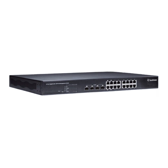
Hardware Description 3. Hardware Description This section gives a physical and functional overview on the 16-Port Gigabit Ethernet with 4-Port Combo Gigabit SFP Web Management Switch. Product Overview Reset Gigabit SFP Display Button Gigabit RJ-45 Front Ethernet Ports The front panel of the Web smart switch consists of 16 10/100/1000BaseT(X) RJ-45 ports and 4 SFP Combo Uplink ports. - Page 10 LED Indicators The LED Indicators present real-time information of systematic operation status. The following table provides description of LED status and their meaning. Color/Status Description No. of LED Amber On Power on Power Power Power off Green On Link Up Link / ACT Green Blinking...
- Page 11 Hardware Description AC Power Input Connect the attached power cord to the AC power input connector; the available AC power input is range from 100-240 V/AC. Ethernet Cable Request The wiring cable types are as below. 10/100BaseT(X): 2-pair UTP/STP Cat. 5 cable, EIA / TIA-568 100-ohm (Max. 100 m) 1000BaseT: 4-pair UTP/STP Cat.
-
Page 12: Preparation For Web Configuration
4. Preparation for Web Configuration The Web management page allows you to use a standard Web-browser such as Microsoft Internet Explorer, Google Chrome or Mozilla Firefox, to configure and interrogate the switch from anywhere on the network. Before you attempt to use the Web user interface to manage switch operation, verify that your switch is properly installed on your network and that every PC on this network can access the switch via the Web browser. - Page 13 Preparation for Web Configuration Launch the Web browser and Login. 1. Launch the Web browser (Internet Explorer or Mozilla Firefox) on the PC. 2. Type http://192.168.0.250 (or the IP address of the switch). And then press Enter. 3. The login screen will appear next. 4.
-
Page 14: User Login
5. User Login This part instructs users how to set up and manage the switch through the Web user interface. Follow the description to understand the procedure. At first, open the Web browser, type http://192.168.0.250 and then the users will see the login page. -
Page 15: Configuration
Configuration 6. Configuration 6.1 System Figure 6-1 The System Configuration page displays the following information: MAC Address: Displays the unique hardware address assigned by manufacturer (default). S/W Version: Displays the switch’s firmware version. H/W Version: Displays the switch’s Hardware version. Active IP Address: Displays current IP address. - Page 16 DHCP Enabled: Click to enable the switch to act as the DHCP Client, and the switch will try getting the IP Address from the DHCP server. Fallback IP address: Manually assign the IP address that the network is using. The default IP is 192.168.0.250.
-
Page 17: Ports
Configuration 6.2 Ports In Port Configuration, you can set and view the operation mode for each port. Figure 6-2 Enable Jumbo Frames: This switch provides more efficient throughput for large sequential data transfers by supporting jumbo frames on Gigabit Ethernet ports up to 9216 bytes. - Page 18 Power Saving Mode: Select Full, Link-up, Link-down or Disable to adjust the power provided to ports based on the length of the cable used to connect to other devices. Only sufficient power is used to maintain connection requirements. ...
-
Page 19: Vlans
Configuration 6.3 VLANs A Virtual LAN (VLAN) is a logical network grouping that limits the broadcast domain, which would allow you to isolate network traffic, so only the members of the same VLAN will receive traffic from the ones of the same VLAN. Basically, creating a VLAN from a switch is logically equivalent of reconnecting a group of network devices to another Layer 2 switch. -
Page 20: Aggregation
6.4 Aggregation Port trunk allows multiple links to be bundled together and act as a single physical link for increased throughput. It provides load balancing, and redundancy of links in a switched inter-network. Actually, the link does not have an inherent total bandwidth equal to the sum of its component physical links. -
Page 21: Lacp
Configuration 6.5 LACP IEEE 802.3ad Link Aggregation Control Protocol (LACP) increases bandwidth by automatically aggregating several physical links together as a logical trunk and providing load balancing and fault tolerance for uplink connections. Figure 6-6 Protocol Enabled: Enables LACP on the associated port. ... -
Page 22: Rstp
6.6 RSTP IEEE 802.1w Rapid Spanning tree protocol (LACP) provides a loop-free network and redundant links to the core network with rapid convergence to ensure faster recovery from failed links, enhancing overall network stability and reliability. Figure 6-7 ... - Page 23 Configuration Figure 6-8 [RSTP Port Configuration] Port: The port ID. It cannot be changed. Aggregations mean any configured trunk group. Protocol Enabled: Click on the tick-box to enable/disable the RSTP protocol for the port. Edge: Expect the port to be an edge port (linking to an end station) or a link to another STP device.
-
Page 24: Igmp Snooping
6.7 IGMP Snooping IGMP Snooping is the process of listening to IGMP network traffic. IGMP Snooping, as implied by the name, is a feature that allows a layer 2 switch to “listen in” on the IGMP conversation between hosts and routers by processing the layer3 IGMP packets sent in a multicast network. -
Page 25: Mirroring
Configuration 6.8 Mirroring Port Mirroring is used on a network switch to send a copy of network packets seen on one switch port (or an entire VLAN) to a network monitoring connection on another switch port. This is commonly used for network appliances that require monitoring of network traffic, such as an intrusion-detection system. -
Page 26: Quality Of Service
6.9 Quality of Service In QoS Mode, select QoS Disabled, 802.1p or DSCP, and click Apply to configure the related parameters. Figure 6-11 802.1p Configuration] Packets are prioritized using the 802.1p field in the VLAN tag. Figure 6-12 ... - Page 27 Configuration [DSCP Configuration] Packets are prioritized using the DSCP (Differentiated Services Code Point) value. Figure 6-13 Prioritize Traffic: Allows the customization of DSCP to Traffic classifiers to quickly set the values in the DSCP Configuration table to a common priority queue. Select Custom if you want to set each value individually.
-
Page 28: Filter
6.10 Filter There are 3 modes that you can choose for filter configuration: Disabled, Static, and DHCP. Figure 6-14 Source IP Filter Disabled: This mode is disabled, no any protection here. Static: The IP address you typed here can not access the switch. ... -
Page 29: Power Over Ethernet
Configuration 6.11 Power over Ethernet PoE technology is a system to pass electrical power safely, along with data, on Ethernet cabling. Power is supplied in common mode over two or more of the differential pairs of sires found in the Ethernet cables and comes from a power supply within a PoE enabled networking devise such as Switch or can be injected into a cable run with a midspan power supply. -
Page 30: Rate Limit
6.12 Rate Limit You can define the certain port as Policer and Shaper before you set up the rate limit. Figure 6-16 No Limit: Allows you to specify that the selected port will have no bandwidth limit. ... -
Page 31: Storm Control
Configuration 6.13 Storm Control Broadcast storms may occur when a device on your network is malfunctioning, or if application programs are not well designed or properly configured. If there is too much broadcast traffic on your network, performance can be severely degraded or everything can come to complete halt. -
Page 32: Monitoring
7. Monitoring 7.1 Statistics Overview User can mirror traffic from any source port to a target port for real-time analysis the following figures shows clearly the statistics overview. Click Clear to renew the details collected and displayed. Click Refresh to reset the details displayed. Figure 7-1 ... -
Page 33: Lacp Status
Monitoring 7.3 LACP Status LACP allows for the automatic detection of links in a Port Trunking Group. Figure 7-3 LACP Port Status Figure 7-4 ... - Page 34 Active LACP ports are capable of processing and sending LACP control frames. This allows LACP compliant devices to negotiate the aggregated link so the group may be changed dynamically as needed. Port: The port number. ...
-
Page 35: Rstp Status
Monitoring 7.4 RSTP Status Figure 7-5 [RSTP VLAN Bridge Overview] VLAN Id: VLAN ID number. Bridge Id: Bridge ID number. Hello Time: Interval (in seconds) at which the root device transmits a configuration message. - Page 36 Topology: Indicates if spanning tree topology is steady or undergoing reconfiguration. (The time required for reconfiguration is extremely short, so no values other that “steady” state are likely to be seen in this field.) Root Id: The priority and MAC address of the device in the Spanning Tree that this ...
-
Page 37: Igmp Status
Monitoring 7.5 IGMP Status IGMP Status shows the IGMP Snooping statistics for the whole switch. Figure 7-6 VLAN ID: VLAN ID number. Querier: Shows whether Querying is enabled. Queries transmitted: Shows the number of transmitted Query packets. ... -
Page 38: Ping
7.6 Ping This command sends ICMP echo request packets to another node on the network. Figure 7-7 [Ping Parameters] Target IP Address: Type the IP address of the host. Count: Set the number of packets to send. ... -
Page 39: Maintenance
Maintenance 8. Maintenance 8.1 Warm Restart Press Yes to restart the switch. The reset will be complete when the power light stops blinking. Figure 8-1 8.2 Factory Default To restore the switch to the default settings, select Factory Default from the left menu and click Yes. -
Page 40: Software Upload
8.3 Software Upload To upgrade the firmware version of the switch, follow the steps below: 1. Click Browse to select the firmware file and click Upload. Figure 8-3 2. After the uploading process is completed, this message appears. Click Yes to activate the new software. -
Page 41: Logout
Restoring Default Settings 9. Logout The administrator has write access for all parameters governing the onboard agent. The user should therefore assign a new administrator password as soon as possible, and store it in a safe place. After finishing configuring the switch, you can click Logout to leave the configuration page. Figure 9-1 ... -
Page 42: Restoring Default Settings
10. Restoring Default Settings You can load the default value with the Reset button or with the Web interface. Hardware To restore the switch to its default settings using the Reset button, follow the steps below: 1. Turn on the switch. 2. - Page 43 Restoring Default Settings 11. Specifications Ports 16 ports Number of Ports 16‐port 10/100/1000BaseT(X) with RJ‐45 Connectors, PoE+ 4‐port SFP Combo Uplink Port Performance MAC Address 8 K Buffer Memory 4 M bits Jumbo Frames 9.6 KB Transmission Method Store and Forward 10/100BaseT(X) Cat. 5 UTP/STP Transmission Media 1000BaseT Cat. 5e, 6 UTP/STP 10 Mbps port ‐ 14,880 pps Filtering/Forwarding Rates 100 Mbps port ‐ 148,800 pps 1000 Mbps port ‐ 1,488,000 pps Smart Features Port Based VLAN 16 Tag Based VLAN 16, VID 1~4094 IGMP Snooping V1 & V2 Link Aggregation up to 8 groups Quality of Service (QoS) up to 4 queues, 802.1p, DSCP ...
Need help?
Do you have a question about the GV-POE1611-V2 and is the answer not in the manual?
Questions and answers