
Related Manuals for GeoVision GV-POE0812


Summary of Contents for GeoVision GV-POE0812
- Page 1 GV-PoE Switch GV-POE0812 User's Manual Before attempting to connect or operate this product, please read these instructions carefully and save this manual for future use. POE0812-A...
- Page 2 GeoVision. Every effort has been made to ensure that the information in this manual is accurate. GeoVision, Inc. makes no expressed or implied warranty of any kind and assumes no responsibility for errors or omissions. No liability is assumed for incidental or consequential damages arising from the use of the information or products contained herein.
-
Page 3: Table Of Contents
Contents 1. Before Starting ....................1 1.1 Safety Precautions ..................2 1.2 Intended Readers ..................3 1.3 Icons for Caution, and Warning ..............3 1.4 Packing List ....................4 1.5 Options ......................5 2. Product Overview .....................6 2.1 Product Brief Description ................7 2.2 Product Specifications ..................8 2.3 Hardware Description ................. - Page 4 4.1.5.3 Security - Switch - Authentication Method ........49 4.1.5.4 Security - Switch - SSH ..............50 4.1.5.5 Security - Switch - HTTPS .............. 51 4.1.5.6 Security - Switch - Access Management .......... 52 4.1.5.7 Security - Switch - SNMP ............... 53 4.1.5.7.1 Security - Switch - SNMP - System ...........
- Page 5 4.1.8.1 Spanning Tree - Bridge Settings ........... 119 4.1.8.2 Spanning Tree - MSTI Mapping ............. 121 4.1.8.3 Spanning Tree - MSTI Priorities ............ 123 4.1.8.4 Spanning Tree - CIST Ports ............124 4.1.8.5 Spanning Tree - MSTI Ports ............127 4.1.9 Configuration - IPMC Profile ...............
- Page 6 4.1.19.3 QoS - Port Scheduler ..............186 4.1.19.4 QoS - Port Shaping ..............190 4.1.19.5 QoS - Port Tag Remarking ............194 4.1.19.6 QoS - Port DSCP ............... 197 4.1.19.7 QoS - DSCP-Based QoS ............199 4.1.19.8 QoS - DSCP Translation ............. 200 4.1.19.9 QoS - DSCP Classification ............
- Page 7 4.2.5.1 Security - Access Management Statistics ........240 4.2.5.2 Security - Network ................ 241 4.2.5.2.1 Security - Network - Port Security - Switch ......241 4.2.5.2.2 Security - Network - Port Security - Port ......... 243 4.2.5.2.3 Security - Network - NAS - Switch .......... 244 4.2.5.2.4 Security - Network - NAS - Port ..........
- Page 8 4.2.11 Monitor - LLDP ................. 292 4.2.11.1 LLDP - Neighbours ..............292 4.2.11.2 LLDP - LLDP-MED Neighbours ........... 294 4.2.11.3 LLDP - PoE ................299 4.2.11.4 LLDP - EEE ................301 4.2.11.5 LLDP - Port Statistics ..............303 4.2.12 Monitor - PoE ................... 305 4.2.13 Monitor - MAC Table .................
-
Page 9: Before Starting
Before Starting 1. Before Starting In Before Starting: This section contains introductory information which includes: Safety Precautions Intended Readers Icons for Note, Caution, and Warning Product Package Contents ... -
Page 10: Safety Precautions
1.1 Safety Precautions FCC Warning This Equipment has been tested and found to comply with the limits of a Class-A digital device, pursuant to Part 15 of the FCC rules. These limits are designed to provide reasonable protection against harmful interference in a residential installation. This equipment generates, uses, and can radiate radio frequency energy. -
Page 11: Intended Readers
Before Starting 1.2 Intended Readers This manual provides information regarding all the aspects and functions needed to install, configure, use, and maintain the product you’ve purchased. This manual is intended for technicians who are familiar with in-depth concepts of networking management and terminologies. 1.3 Icons for Caution, and Warning To install, configure, use, and maintain this product properly, please pay attention when you see these icons in this manual:... -
Page 12: Packing List
Console cable x 1 Screw x 8, Rack Mount Kit x 1 Software CD x 1 GV-POE0812 Quick Start Guide x 1 AC Power Cord x 1 Note: If any item listed in this table above is missing or damaged, please contact... -
Page 13: Options
Before Starting 1.5 Options Optional devices can expand your GV-POE0812’s capabilities and versatility. Contact your dealer for more information. The SFP Transceiver is designed to plug into the SFP port of the GV-POE Switch and is the interface between the switch and optical fiber cables. -
Page 14: Product Overview
2. Product Overview In Product Overview: This section will give you an overview of this product, including its feature functions and hardware/software specifications. Product Brief Description Product Specification Hardware Description Hardware Installation... -
Page 15: Product Brief Description
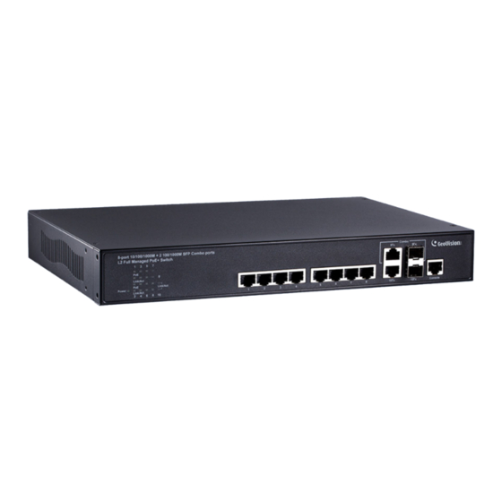
Product Overview 2.1 Product Brief Description Introduction This switch is 8-port 10/100/1000Base-T PoE + 2 Gigabit SFP/RJ45 Copper Combo Ports L2+ Full Managed Switch that is designed for small or medium network environment to strengthen its network connection. The 8 PoE ports support IEEE 802.3at/af PoE technology, up to 30W per port and maximum 100m transmission distance. -
Page 16: Product Specifications
2.2 Product Specifications Interface 10/100/1000 Base RJ45 Ports 100/1000Base-X SFP and 1000 RJ45 Combo Port Console Port for CLI Management System Performance Packet Buffer 4 Mbits MAC Address Table Size Switching Capacity 20 Gbps 1,488,000 pps with 64 Forwarding Rate bytes packets PoE Features IEEE 802.3 af/at... - Page 17 Product Overview QoS Features Number of priority queue 8 queues/port Ingress 1 Kbps / 1 pps granularity Rate Limiting Egress 1 Kbps / 1 pps granularity DiffServ (RFC2474 Remarking) Scheduling (WRR, Strict, Hybrid) IEEE 802.1p IP ToS precedence, IP DSCP ...
- Page 18 Standard IEEE 802.3 – 10BaseT IEEE 802.3u - 100BaseTX IEEE 802.3ab - 1000BaseT IEEE 802.3z 1000GBaseSX/LX/ZX IEEE 802.3af Power over Ethernet (PoE) IEEE 802.3at Power over Ethernet (PoE+) IEEE 802.3az - Energy Efficient Ethernet (EEE) ...
-
Page 19: Hardware Description
Product Overview 2.3 Hardware Description This section mainly describes the hardware of Full-Management PoE switch and gives a physical and functional overview on the certain switch. Front Panel The front panel of the Full-Management PoE switch consists of 8 10/100/1000 Base-TX RJ-45 ports and 2 Gigabit uplink SFP ports. - Page 20 LED Indicators The LED Indicators present real-time information of systematic operation status. The following table provides description of LED status and their meaning. Color Status Description No. of LED Amber Power on Power Power Power off Linked Up Green Link / Blinking Data activating No connection...
- Page 21 Product Overview Rear Panel The rear panel of the Full-Management PoE switch contains a power switch and an IEC 60320 plug for power supply.
-
Page 22: Hardware Installation
2.4 Hardware Installation To install the Full-Management PoE switch, please place it on a large flat surface with a power socket close by. This surface should be clean, smooth, and level. Also, please make sure that there is enough space around the Full-Management PoE switch for RJ45 cable, power cord and ventilation. -
Page 23: Preparing For Management
Preparing for Management 3. Preparing for Management In Preparing for Management: This section will guide your how to manage this product via serial console, management web page, and Telnet/SSH interface. The switch provides both out-of-band and in-band managements. Out-of-band Management: You can configure the switch via RS232 console cable without having the switch or your PC connecting to a network. -
Page 24: Preparation For Serial Console
3.1 Preparation for Serial Console Inside the product package, you can find an RS-232 console cable. Before managing your switch via out-of-band management, please attach this cable’s RJ45 connector to your switch’s console port and its RS-232 female connector to your PC’s COM port. - Page 25 Preparing for Management Set the serial port settings as: Baud Rate: 115200, Data Bit: 8, Parity: None, Stop Bit: 1, Row Control: None. The system will prompt you to login the out-of-band management CLI. The default username/password is admin/admin.
-
Page 26: Preparation For Web Interface
IE, Google Chrome, or Mozilla Firefox) to configure and monitor the switch from anywhere on the network. Note: GV-POE0812 does not support IE8. Before using the web interface to manage your switch, please verify that your switch and your PC are on the same network. Please follow the steps down below... - Page 27 Preparing for Management Type 192.168.0.250 (or the IP address of the switch) in the web browser’s URL field, and press Enter. The web browser will prompt you to sign in. The default username/password for the configuration web page is admin/admin. For more information, please refer to Appendix B: IP Configuration for Your...
-
Page 28: Preparation For Telnet/Ssh Interface
3.3 Preparation for Telnet/SSH Interface Both telnet and SSH (Secure Shell) are network protocols that provide a text-based command line interface (CLI) for in-band system management. However, only SSH provides a secure channel over an un-secured network, where all transmitted data are encrypted. This switch supports both telnet and SSH management CLI. - Page 29 Preparing for Management If you’re connecting to the switch via SSH for the first time, a “PuTTY Security Alert” window will pop up. Please press “Yes” to continue. This window won’t pop up if you’re using telnet to connect to the in-band management CLI.
-
Page 30: Web Management
4. Web Management In Web Management: As mentioned in Chapter 2.2. Preparation for Web Interface, This switch provides a web-based management interface. You can make all settings and monitor system status with this management web page. Configuration/Monitor options included in the management web page can be divided into the following 4 categories, which will be discussed in detail in this chapter: ... -
Page 31: Web Management - Configure
Web Management 4.1 Web Management - Configure Here you can access all the configuration options of the switch. The configuration options here include: System: Here you can configure basic system settings such as system information, switch IP, NTP, system time and log. ... - Page 32 MAC Table: When a network device is connected to the switch, the switch will keep its MAC address on the MAC table. This section provides settings for the switch’s MAC address table. VLANs: VLAN stands for Virtual LAN, which allows you to separate ports into ...
-
Page 33: Configuration - System
Web Management 4.1.1 Configuration - System 4.1.1.1. System - Information The switch system information is provided here. System Contact The textual identification of the contact person for this managed node, together with information on how to contact this person. The allowed string length is 0 to 255, and the allowed content is the ASCII characters from 32 to 126. -
Page 34: System - Ip
4.1.1.2 System - IP Configure IP basic settings, control IP interfaces and IP routes. The maximum number of interfaces supported is 128 and the maximum number of routes is 32. Basic Settings Mode Configure whether the IP stack should act as a Host or a Router. In Host mode, IP traffic between interfaces will not be routed. - Page 35 Web Management VLAN The VLAN associated with the IP interface. Only ports in this VLAN will be able to access the IP interface. This field is only available for input when creating an new interface. IPv4 DHCP Enabled Enable the DHCP client by checking this box. If this option is enabled, the system will configure the IPv4 address and mask of the interface using the DHCP protocol.
- Page 36 a IPv6 address. The field may be left blank if IPv6 operation on the interface is not desired. IP Routes Delete Select this option to delete an existing IP route. Network The destination IP network or host address of this route. Valid format is dotted decimal notationor a valid IPv6 notation.
-
Page 37: System - Ntp
Web Management 4.1.1.3 System - NTP NTP stands for Network Time Protocol, which allows switch to perform clock synchronization with the NTP server. Mode You can enable or disable NTP function on this switch: Enabled: Enable NTP client mode. ... -
Page 38: System - Time
4.1.1.4 System - Time This page allows you to configure the Time Zone and daylight saving time. Time Zone Configuration Time Zone: Lists various Time Zones world wide. Select appropriate Time Zone from the drop down and click Save to set. ... - Page 39 Web Management Start time settings Week - Select the starting week number. Day - Select the starting day. Month - Select the starting month. Hours - Select the starting hour. Minutes - Select the starting minute. End time settings Week - Select the ending week number.
-
Page 40: System - Log
4.1.1.5 System - Log Configure System Log on this page. Server Mode When enabled, the system log message will be sent out to the system log server you set here. The system log protocol is based on UDP communication and received on UDP port 514 and the system log server will not send acknowledgments back sender since UDP is a connectionless protocol and it does not provide acknowledgments. -
Page 41: Configuration - Green Ethernet
Web Management 4.1.2 Configuration - Green Ethernet 4.1.2.1 Green Ethernet - Port Power Savings EEE is a power saving option that reduces the power usage when there is low or no traffic utilization. EEE works by powering down circuits when there is no traffic. When a port gets data to be transmitted all circuits are powered up. - Page 42 ActiPHY Link down power savings enabled. ActiPHY works by lowering the power for a port when there is no link. The port is power up for short moment in order to determine if cable is inserted. PerfectReach Cable length power savings enabled. PerfectReach works by determining the cable length and lowering the power for ports with short cables.
-
Page 43: Configuration - Ports
Web Management 4.1.3 Configuration - Ports This page displays current port configurations. Ports can also be configured here. The port settings relate to the currently selected stack unit, as reflected by the page header. Port This is the logical port number for this row. Link The current link state is displayed graphically. - Page 44 Flow Control When Auto Speed is selected on a port, this section indicates the flow control capability that is advertised to the link partner. When a fixed-speed setting is selected, that is what is used. The Current Rx column indicates whether pause frames on the port are obeyed, and the Current Tx column indicates whether pause frames on the port are transmitted.
-
Page 45: Configuration - Dhcp
Web Management 4.1.4 Configuration - DHCP 4.1.4.1 DHCP - Server 4.1.4.1.1 DHCP - Server - Mode This page configures global mode and VLAN mode to enable/disable DHCP server per system and per VLAN. Global Mode Configure operation mode to enable/disable DHCP server per system. Mode Configure the operation mode per system. - Page 46 Mode Indicate the the operation mode per VLAN. Possible modes are: Enabled: Enable DHCP server per VLAN. Disabled: Disable DHCP server pre VLAN. Buttons Add VLAN Range: Click to add a new VLAN range. Save: Click to save changes. ...
-
Page 47: Dhcp - Server - Excluded Ip
Web Management 4.1.4.1.2 DHCP - Server - Excluded IP This page configures excluded IP addresses. DHCP server will not allocate these excluded IP addresses to DHCP client. Excluded IP Address Configure excluded IP addresses. IP Range Define the IP range to be excluded IP addresses. The first excluded IP must be smaller than or equal to the second excluded IP. -
Page 48: Dhcp - Server - Pool
4.1.4.1.3 DHCP - Server - Pool This page manages DHCP pools. According to the DHCP pool, DHCP server will allocate IP address and deliver configuration parameters to DHCP client. Pool Setting Add or delete pools. Adding a pool and giving a name is to create a new pool with "default" configuration. If you want to configure all settings including type, IP subnet mask and lease time, you can click the pool name to go into the configuration page. - Page 49 Web Management Lease Time Display lease time of the pool. Buttons Add New Pool: Click to add a new DHCP pool. Save: Click to save changes. Reset: Click to undo any changes made locally and revert to previously saved values.
-
Page 50: Dhcp - Snooping
4.1.4.2 DHCP - Snooping Configure DHCP Snooping on this page. Snooping Mode Indicates the DHCP snooping mode operation. Possible modes are: Enabled: Enable DHCP snooping mode operation. When DHCP snooping mode operation is enabled, the DHCP request messages will be forwarded to trusted ports and only allow reply packets from trusted ports. -
Page 51: Dhcp - Relay
Web Management 4.1.4.3 DHCP - Relay A DHCP relay agent is used to forward and to transfer DHCP messages between the clients and the server when they are not in the same subnet domain. It stores the incoming interface IP address in the GIADDR field of the DHCP packet. - Page 52 Relay Information Policy Indicates the DHCP relay information option policy. When DHCP relay information mode operation is enabled, if the agent receives a DHCP message that already contains relay agent information it will enforce the policy. The 'Replace' policy is invalid when relay information mode is disabled. Possible policies are: ...
-
Page 53: Configuration - Security
Web Management 4.1.5 Configuration - Security This section provides settings regarding to the switch’s security functions. Settings provided here can be divided into 3 categories: Switch: Here you can make security settings regarding to the switch itself. Network: Providing security settings regarding to the network. ... - Page 54 This page configures a user. User Name A string identifying the user name that this entry should belong to. The allowed string length is 1 to 31. The valid user name is a combination of letters, numbers and underscores. Password The password of the user.
-
Page 55: Security - Switch - Privilege Level
Web Management 4.1.5.2 Security - Switch - Privilege Level This page provides an overview of the privilege levels. - Page 56 Group Name The name identifying the privilege group. In most cases, a privilege level group consists of a single module (e.g. LACP, RSTP or QoS), but a few of them contains more than one. The following description defines these privilege level groups in details: System: Contact, Name, Location, Timezone, Daylight Saving Time, Log.
-
Page 57: Security - Switch - Authentication Method
Web Management 4.1.5.3 Security - Switch - Authentication Method This page allows you to configure how a user is authenticated when he logs into the stack via one of the management client interfaces. Client The management client for which the configuration below applies. Method Method can be set to one of the following values: ... -
Page 58: Security - Switch - Ssh
4.1.5.4 Security - Switch - SSH Configure SSH on this page. Mode Indicates the SSH mode operation. Possible modes are: Enabled: Enable SSH mode operation. Disabled: Disable SSH mode operation. Buttons Save: Click to save changes. Reset: Click to undo any changes made locally and revert to previously saved values. -
Page 59: Security - Switch - Https
Web Management 4.1.5.5 Security - Switch - HTTPS Configure HTTPS on this page. Mode Indicates the HTTPS mode operation. When the current connection is HTTPS, to apply HTTPS disabled mode operation will automatically redirect web browser to an HTTP connection. Possible modes are: ... -
Page 60: Security - Switch - Access Management
4.1.5.6 Security - Switch - Access Management Configure access management table on this page. The maximum number of entries is 16. If the application's type match any one of the access management entries, it will allow access to the switch. Mode Indicates the access management mode operation. -
Page 61: Security - Switch - Snmp
Web Management 4.1.5.7 Security - Switch - SNMP 4.1.5.7.1 Security - Switch - SNMP - System Configure SNMP on this page. Mode Indicates the SNMP mode operation. Possible modes are: Enabled: Enable SNMP mode operation. Disabled: Disable SNMP mode operation. Version Indicates the SNMP supported version. - Page 62 SNMP Trap Configuration Configure SNMP trap on this page. Trap Mode Indicates the SNMP trap mode operation. Possible modes are: Enabled: Enable SNMP trap mode operation. Disabled: Disable SNMP trap mode operation. Trap Version Indicates the SNMP trap supported version. Possible versions are: ...
- Page 63 Web Management Trap Destination IPv6 Address Indicates the SNMP trap destination IPv6 address. IPv6 address is in 128-bit records represented as eight fields of up to four hexadecimal digits with a colon separating each field (:). For example, 'fe80::215:c5ff:fe03:4dc7'. The symbol '::' is a special syntax that can be used as a shorthand way of representing multiple 16-bit groups of contiguous zeros;...
- Page 64 Buttons Save: Click to save changes. Reset: Click to undo any changes made locally and revert to previously saved values. ...
-
Page 65: Security - Switch - Snmp - Trap
Web Management 4.1.5.7.2 Security - Switch - SNMP - Trap Configure SNMP trap on this page. Global Settings Mode Indicates the trap mode operation. Possible modes are: Enabled: Enable SNMP trap mode operation. Disabled: Disable SNMP trap mode operation. ... - Page 66 Destination Address Indicates the SNMP trap destination address. It allow a valid IP address in dotted decimal notation ('x.y.z.w'). And it also allow a valid hostname. A valid hostname is a string drawn from the alphabet (A-Za-z), digits (0-9), dot (.), dash (-). Spaces are not allowed, the first character must be an alpha character, and the first and last characters must not be a dot or a dash.
-
Page 67: Security - Switch - Snmp - Community
Web Management 4.1.5.7.3 Security - Switch - SNMP - Community Configure SNMPv3 community table on this page. The entry index key is Community. Delete Check to delete the entry. It will be deleted during the next save. Community Indicates the community access string to permit access to SNMPv3 agent. The allowed string length is 1 to 32, and the allowed content is ASCII characters from 33 to 126. -
Page 68: Security - Switch - Snmp - User
4.1.5.7.4 Security - Switch - SNMP - User Configure SNMPv3 user table on this page. The entry index keys are Engine ID and User Name. Delete Check to delete the entry. It will be deleted during the next save. Engine ID An octet string identifying the engine ID that this entry should belong to. - Page 69 Web Management Authentication Protocol Indicates the authentication protocol that this entry should belong to. Possible authentication protocols are: None: No authentication protocol. MD5: An optional flag to indicate that this user uses MD5 authentication protocol. SHA: An optional flag to indicate that this user uses SHA authentication protocol. The value of security level cannot be modified if entry already exists.
-
Page 70: Security - Switch - Snmp - Groups
4.1.5.7.5 Security - Switch - SNMP - Groups Configure SNMPv3 group table on this page. Delete Check to delete the entry. It will be deleted during the next save. Security Model Indicates the security model that this entry should belong to. Possible security models are: ... -
Page 71: Security - Switch - Snmp - Views
Web Management 4.1.5.7.6 Security - Switch - SNMP - Views Configure SNMPv3 view table on this page. The entry index keys are View Name and OID Subtree. Delete Check to delete the entry. It will be deleted during the next save. View Name A string identifying the view name that this entry should belong to. -
Page 72: Security - Switch - Snmp - Access
4.1.5.7.7 Security - Switch - SNMP - Access Configure SNMPv3 access table on this page. Delete Check to delete the entry. It will be deleted during the next save. Group Name A string identifying the group name that this entry should belong to. The allowed string length is 1 to 32, and the allowed content is ASCII characters from 33 to 126. -
Page 73: Security - Switch - Rmon
Web Management 4.1.5.8 Security - Switch - RMON 4.1.5.8.1 Security - Switch - RMON - Statistics Configure RMON Statistics table on this page. The entry index key is ID. Delete Check to delete the entry. It will be deleted during the next save. Indicates the index of the entry. -
Page 74: Security - Switch - Rmon - History
4.1.5.8.2 Security - Switch - RMON - History Configure RMON History table on this page. The entry index key is ID. Delete Check to delete the entry. It will be deleted during the next save. Indicates the index of the entry. The range is from 1 to 65535. Data Source Indicates the port ID which wants to be monitored. -
Page 75: Security - Switch - Rmon - Alarm
Web Management 4.1.5.8.3 Security - Switch - RMON - Alarm Configure RMON Alarm table on this page. The entry index key is ID. Delete Check to delete the entry. It will be deleted during the next save. Indicates the index of the entry. The range is from 1 to 65535. Interval Indicates the interval in seconds for sampling and comparing th e rising and falling threshold. - Page 76 Delta: Calculate the difference between samples (default). Value The value of the statistic during the last sampling period. Startup Alarm The method of sampling the selected variable and calcula ting the value to be compared against the thresholds, poss ible sample types are: ...
-
Page 77: Security - Switch - Rmon - Event
Web Management 4.1.5.8.4 Security - Switch - RMON - Event Configure RMON Event table on this page. The entry index key is ID. Delete Check to delete the entry. It will be deleted during the next save. Indicates the index of the entry. The range is from 1 to 65535. Desc Indicates this event, the string length is from 0 to 127, default is a null string. -
Page 78: Security - Network - Limit Control
4.1.5.9 Security - Network - Limit Control This page allows you to configure the Port Security Limit Control system and port settings. Limit Control allows for limiting the number of users on a given port. A user is identified by a MAC address and VLAN ID. - Page 79 Web Management suppose that the end-host logs off or powers down. If it wasn't for aging, the end-host would still take up resources on this switch and will be allowed to forward. To overcome this situation, enable agin With aging enabled, a timer is started once the end-host gets secured. When the timer expires, the switch starts looking for frames from the end-host, and if such frames are not seen within the next Aging Period, the end-host is assumed to be disconnected, and the corresponding resources are freed on the switch.
- Page 80 "Shutdown" actions described above will be taken. This column shows the current state of the port as s een from the Limit Control's point of view. The state ta kes one of four values: Disabled: Limit Control is either globally disabled or disabled on the port. ...
-
Page 81: Security - Network - Nas (Network Access Server)
Web Management 4.1.5.10 Security - Network - NAS (Network Access Server) This page allows you to configure the IEEE 802.1X and MAC-based authentication system and port settings. The IEEE 802.1X standard defines a port-based access control procedure that prevents unauthorize d access to a network by requiring users to first submit credentials for authentication. - Page 82 changed. It does not involve communication between the switch and the client, and therefore doesn't imply that a client is still present on a port (see Aging Period below). Re-authentication Period Determines the period, in seconds, after which a connected client must be re-authenticated. This is only active if the Re-authentication Enabled checkbox is checked.
- Page 83 Web Management "Configuration→Security→AAA" page) - the client is put on hold in the Unauthori zed state. The hold timer does not count during an on-going authentication. In MAC-based Auth. mode, the switch will ignore new frames coming from the client d uring the hold time.
- Page 84 Guest VLAN ID This is the value t hat a port's Port VLAN ID is set to if a port is moved into the Guest VLAN. It is only changeable if the Guest VLAN option is globally enabled. Valid values are in the range [1; 4095]. Max.
- Page 85 Web Management Port Configuration The table has one row for each port on the selected switch in the stack and a number of columns, which are: Port The port number for which the configuration below applies. Admin State If NAS is globally enabled, this selection controls the port's authentication mode. The following modes are available: Force Authorized In this mode, the switch will send one EAPOL Success frame when the port link comes up, and any...
- Page 86 or block traffic on the switch port connected to the supplicant. Note: Suppose two backend servers are enabled and that the server timeout is configured to X seconds (using the AAA configuration page), and suppose that the first server in the list is currently down (but not considered dead).
- Page 87 Web Management the supplicant's MAC address, which is obtained from the first EAPOL Start or EAPOL Response Identity frame sent by the supplicant. An exception to this is when no supplicants are attached. In this case, the switch sends EAPOL Request Identity frames using the BPDU multicast MAC address as destination - to wake up any supplicants that might be on the port.
- Page 88 This option is only available for single-client modes, i.e. Port-based 802.1X Single 802.1X RADIUS attributes used in identifying a QoS Class: The User-Priority-Table attribute defined in RFC4675 forms the basis for identifying the QoS Class in an Access-Accept packet. Only the first occurrence of the attribute in the packet will be considered, and to be valid, it must follow this rule: ...
- Page 89 Web Management The switch looks for the first set of these attributes that have the same Tag value and fulfil the following requirements (if Tag == 0 is used, the Tunnel-Private-Group-ID does not need to include a Tag): Value of Tunnel-Medium-Type must be set to "IEEE-802" (ordinal 6). ...
- Page 90 supplicant according to the port mode. If an EAPOL frame is received, the port will never be able to go back into the Guest VLAN if the "Allow Guest VLAN if EAPOL Seen" is disabled. Port State The current state of the port. It can undertake one of the following values: Globally Disabled: NAS is globally disabled.
-
Page 91: Security - Network - Acl
Web Management 4.1.5.11 Security - Network - ACL 4.1.5.11.1 Security - Network - ACL - Ports Configure the ACL parameters (ACE) of each switch port. These parameters will affect frames received on a port unless the frame matches a specific ACE. The settings relate to the currently selected stack unit, as reflected by the page header. - Page 92 The default value is "Disabled". Please note that the System Log memory size and logging rate is limited. Shutdown Specify the port shut down operation of this port. The allowed values are: Enabled: If a frame is received on the port, the port will be disabled. ...
-
Page 93: Security - Network - Acl - Rate Limiter
Web Management 4.1.5.11.2 Security - Network - ACL - Rate Limiter Configure the rate limiter for the ACL of the switch. Rate Limiter ID The rate limiter ID for the settings contained in the same row. Rate The allowed values are: 0-131071 in pps Unit Specify the rate unit. -
Page 94: Security - Network - Acl - Access Control List
4.1.5.11.3 Security - Network - ACL - Access Control List This page shows the Access Control List (ACL), which is made up of the ACEs defined on this switch. Each row describes the ACE that is defined. The maximum number of ACEs is 512 on each switch. - Page 95 Web Management Port Redirect Indicates the port redirect operation of the ACE. Frames matching the ACE are redirected to the port number. The allowed values are Disabled or a specific port number. When Disabled is displayed, the port redirect operation is disabled. Counter The counter indicates the number of times the ACE was hit by a frame.
- Page 96 Configure an ACE (Access Control Entry) on this page. An ACE consists of several parameters. These parameters vary according to the frame type that you select. First select the ingress port for the ACE, and then select the frame type. Different parameter options are displayed depending on the frame type selected.
- Page 97 Web Management Frame Type Select the frame type for this ACE. These frame types are mutually exclusive. Any: Any frame can match this ACE. Ethernet Type: Only Ethernet Type frames can match this ACE. The IEEE 802.3 describes the value of Length/Type Field specifications to be greater than or equal to 1536 decimal (equal to 0600 hexadecimal).
- Page 98 MAC Parameters SMAC Filter (Only displayed when the frame type is Ethernet Type or ARP.) Specify the source MAC filter for this ACE. Any: No SMAC filter is specified. (SMAC filter status is "don't-care".) Specific: If you want to filter a specific source MAC address with this ACE, choose this value. A field for entering an SMAC value appears.
- Page 99 Web Management VLAN Parameters VLAN ID Filter Specify the VLAN ID filter for this ACE. Any: No VLAN ID filter is specified. (VLAN ID filter status is "don't-care".) Specific: If you want to filter a specific VLAN ID with this ACE, choose this value. A field for entering a VLAN ID number appears.
- Page 100 Request: Frame must have ARP Request or RARP Request OP flag set. Reply: Frame must have ARP Reply or RARP Reply OP flag. Sender IP Filter Specify the sender IP filter for this ACE. Any: No sender IP filter is specified. (Sender IP filter is "don't-care".) ...
- Page 101 Web Management 0: RARP frames where THA is not equal to the target MAC address. 1: RARP frames where THA is equal to the target MAC address. Any: Any value is allowed ("don't-care"). IP/Ethernet Length Specify whether frames can hit the action according to their ARP/RARP hardware address length (HLN) and protocol address length (PLN) settings.
- Page 102 IP Parameters The IP parameters can be configured when Frame Type "IPv4" is selected. IP Protocol Filter Specify the IP protocol filter for this ACE. Any: No IP protocol filter is specified ("don't-care"). Specific: If you want to filter a specific IP protocol filter with this ACE, choose this value. A field for entering an IP protocol filter appears.
- Page 103 Web Management able to match this entry. Yes: IPv4 frames where the MF bit is set or the FRAG OFFSET field is greater than zero must be able to match this entry. Any: Any value is allowed ("don't-care"). IP Option Specify the options flag setting for this ACE.
- Page 104 ICMP Parameters ICMP Type Filter Specify the ICMP filter for this ACE. Any: No ICMP filter is specified (ICMP filter status is "don't-care"). Specific: If you want to filter a specific ICMP filter with this ACE, you can enter a specific ICMP ...
- Page 105 Web Management TCP/UDP Parameters TCP/UDP Source Filter Specify the TCP/UDP source filter for this ACE. Any: No TCP/UDP source filter is specified (TCP/UDP source filter status is "don't-care"). Specific: If you want to filter a specific TCP/UDP source filter with this ACE, you can enter a ...
- Page 106 enter a specific TCP/UDP destination range value. A field for entering a TCP/UDP destination value appears. TCP/UDP Destination Number When "Specific" is selected for the TCP/UDP destination filter, you can enter a specific TCP/UDP destination value. The allowed range is 0 to 65535. A frame that hits this ACE matches this TCP/UDP destination value.
- Page 107 Web Management TCP URG Specify the TCP "Urgent Pointer field significant" (URG) value for this ACE. 0: TCP frames where the URG field is set must not be able to match this entry. 1: TCP frames where the URG field is set must be able to match this entry. ...
-
Page 108: Security - Network - Ip Source Guard
4.1.5.12 Security - Network - IP Source Guard 4.1.5.12.1. Security - Network - IP Source Guard - Configuration This page provides IP Source Guard related configuration. Mode of IP Source Guard Configuration Enable the Global IP Source Guard or disable the Global IP Source Guard. All configured ACEs will be lost when the mode is enabled. -
Page 109: Security - Network - Ip Source Guard - Static Table
Web Management 4.1.5.12.2 Security - Network - IP Source Guard - Static Table Delete Check to delete the entry. It will be deleted during the next save. Port The logical port for the settings. VLAN ID The vlan id for the settings. IP Address Allowed Source IP address. -
Page 110: Security - Network - Arp Inspection
4.1.5.13 Security - Network - ARP Inspection 4.1.5.13.1 Security - Network - ARP Inspection - Port Configuration This page provides ARP Inspection related configuration. Mode Enable the Global ARP Inspection or disable the Global ARP Inspection. Port Mode Configuration Specify ARP Inspection is enabled on which ports. Only when both Global Mode and Port Mode on a given port are enabled, ARP Inspection is enabled on this given port. - Page 111 Web Management Only the Global Mode and Port Mode on a given port are enabled, and the setting of "Check VLAN" is disabled, the log type of ARP Inspection will refer to the port setting. There are four log types and possible types are: ...
-
Page 112: Security - Network - Arp Inspection - Vlan Configuration
4.1.5.13.2 Security - Network - ARP Inspection – VLAN Configuration This page provides ARP Inspection related configuration. Navigating the VLAN Configuration Each page shows up to 9999 entries from the VLAN table, default being 20, selected through the "entries per page" input field. When first visited, the web page will show the first 20 entries from the beginning of the VLAN Table. -
Page 113: Security - Network - Arp Inspection - Static Table
Web Management 4.1.5.13.3 Security - Network - ARP Inspection - Static Table Delete Check to delete the entry. It will be deleted during the next save. Port The logical port for the settings. VLAN ID The vlan id for the settings. MAC Address Allowed Source MAC address in ARP request packets. -
Page 114: Security - Network - Arp Inspection - Dynamic Table
4.1.5.13.4 Security - Network - ARP Inspection - Dynamic Table Entries in the Dynamic ARP Inspection Table are shown on this page. The Dynamic ARP Inspection Table contains up to 1024 entries, and is sorted first by port, then by VLAN ID, then by MAC address, and then by IP address. - Page 115 Web Management Refresh: Refreshes the displayed table starting from the input fields. Save: Click to save changes. Reset: Click to undo any changes made locally and revert to previously saved values. <<: Updates the table starting from the first entry in the Dynamic ARP Inspection Table. ...
-
Page 116: Security - Aaa
4.1.5.14 Security – AAA 4.1.5.14.1 Security - AAA - RADIUS This page allows you to configure the RADIUS servers. Global Configuration Timeout Timeout is the number of seconds, in the range 1 to 1000, to wait for a reply from a RADIUS server before retransmitting the request. - Page 117 Web Management NAS-IP-Address (Attribute 4) The IPv4 address to be used as attribute 4 in RADIUS Access-Request packets. If this field is left blank, the IP address of the outgoing interface is used. NAS-IPv6-Address (Attribute 95) The IPv6 address to be used as attribute 95 in RADIUS Access-Request packets. If this field is left blank, the IP address of the outgoing interface is used.
- Page 118 Adding a New Server Click Add New Server button to add a new RADIUS server. An empty row is added to the table, and the RADIUS server can be configured as needed. Up to 5 servers are supported. The Delete button can be used to undo the addition of the new server. Buttons ...
-
Page 119: Security - Aaa -Tacacs
Web Management 4.1.5.14.2 Security - AAA -TACACS+ This page allows you to configure the TACACS+ servers. Global Configuration These setting are common for all of the TACACS+ servers. Timeout Timeout is the number of seconds, in the range 1 to 1000, to wait for a reply from a TACACS+ server before it is considered to be dead. - Page 120 Timeout This optional setting overrides the global timeout value. Leaving it blank will use the global timeout value. This optional setting overrides the global key. Leaving it blank will use the global key. Adding a New Server Click Add New Server button to add a new TACACS+ server. An empty row is added to the table, and the TACACS+ server can be configured as needed.
-
Page 121: Configuration - Aggregation
Web Management 4.1.6 Configuration - Aggregation 4.1.6.1 Aggregation - Static This page is used to configure the Aggregation hash mode and the aggregation group. Hash Code Contributors Source MAC Address The Source MAC address can be used to calculate the destination port for the frame. - Page 122 Aggregation Group Configuration Locality Indicates the aggregation group type. This field is only valid for stackable switches. Global: The group members may reside on different units in the stack. Each global aggregation may consist of up to 8 members. ...
-
Page 123: Aggregation - Lacp
Web Management 4.1.6.2 Aggregation - LACP This page allows the user to inspect the current LACP port configurations, and possibly change them as well. The LACP port settings relate to the currently selected stack unit, as reflected by the page header. Port The switch port number. - Page 124 Save: Click to save changes. Reset: Click to undo any changes made locally and revert to previously saved values.
-
Page 125: Configuration - Loop Protection
Web Management 4.1.7 Configuration - Loop Protection This page allows the user to inspect the current Loop Protection configurations, and possibly change them as well. General Settings Enable Loop Protection Controls whether loop protections is enabled (as a whole). Transmission Time The interval between each loop protection PDU sent on each port. - Page 126 Port Configuration Port The switch port number of the port. Enable Controls whether loop protection is enabled on this switch port. Action Configures the action performed when a loop is detected on a port. Valid values are Shutdown Port, Shutdown Port and Log or Log Only. Tx Mode Controls whether the port is actively generating loop protection PDU's, or whether it is just passively looking for looped PDU's.
-
Page 127: Configuration - Spanning Tree
Web Management 4.1.8 Configuration - Spanning Tree 4.1.8.1 Spanning Tree - Bridge Settings This page allows you to configure STP system settings. The settings are used by all STP Bridge instances in the Switch Stack. Basic Settings Protocol Version The MSTP / RSTP / STP protocol version setting. Valid values are STP, RSTP and MSTP. - Page 128 distribute its BPDU information to. Valid values are in the range 6 to 40 hops. Transmit Hold Count The number of BPDU's a bridge port can send per second. When exceeded, transmission of the next BPDU will be delayed. Valid values are in the range 1 to 10 BPDU's per second.
-
Page 129: Spanning Tree - Msti Mapping
Web Management 4.1.8.2 Spanning Tree - MSTI Mapping This page allows the user to inspect the current STP MSTI bridge instance priority configurations, and possibly change them as well. Configuration Identification Configuration Name The name identifying the VLAN to MSTI mapping. Bridges must share the name and revision (see below), as well as the VLAN-to-MSTI mapping configuration in order to share spanning trees for MSTI's (Intra-region). - Page 130 VLANs Mapped The list of VLANs mapped to the MSTI. The VLANs can be given as a single (xx, xx being between 1 and 4094) VLAN, or a range (xx-yy), each of which must be separated with comma and/or space. A VLAN can only be mapped to one MSTI. An unused MSTI should just be left empty.
-
Page 131: Spanning Tree - Msti Priorities
Web Management 4.1.8.3 Spanning Tree - MSTI Priorities This page allows the user to inspect the current STP MSTI bridge instance priority configurations, and possibly change them as well. MSTI The bridge instance. The CIST is the default instance, which is always active. Priority Controls the bridge priority. -
Page 132: Spanning Tree - Cist Ports
4.1.8.4 Spanning Tree - CIST Ports This page allows the user to inspect the current STP CIST port configurations, and possibly change them as well. This page contains settings for physical and aggregated ports. The aggregation settings are stack global. The STP port settings relate to the currently selected stack unit, as reflected by the page header. - Page 133 Web Management operEdge (state flag) Operational flag describing whether the port is connecting directly to edge devices. (No Bridges attached). Transition to the forwarding state is faster for edge ports (having operEdge true) than for other ports. The value of this flag is based on AdminEdge and AutoEdge fields.
- Page 134 Transition to the forwarding state is faster for point-to-point LANs than for shared media. Buttons Save: Click to save changes. Reset: Click to undo any changes made locally and revert to previously saved values.
-
Page 135: Spanning Tree - Msti Ports
Web Management 4.1.8.5 Spanning Tree - MSTI Ports This page allows the user to inspect the current STP MSTI port configurations, and possibly change them as well. An MSTI port is a virtual port, which is instantiated separately for each active CIST (physical) port for each MSTI instance configured on and applicable to the port. - Page 136 Priority Controls the port priority. This can be used to control priority of ports having identical port cost. (See above). Buttons Get: Click to retrieve settings for a specific MSTI. Save: Click to save changes. Reset: Click to undo any changes made locally and revert to previously saved values.
-
Page 137: Configuration - Ipmc Profile
Web Management 4.1.9 Configuration - IPMC Profile 4.1.9.1 IPMC Profile - Profile Table This page provides IPMC Profile related configurations. The IPMC profile is used to deploy the access control on IP multicast streams. It is allowed to create at maximum 64 Profiles with at maximum 128 corresponding rules for each. - Page 138 Rule When the profile is created, click the edit button to enter the rule setting page of the designated profile. Summary about the designated profile will be shown by clicking the view button. You can manage or inspect the rules of the designated profile by using the following buttons: ...
-
Page 139: Ipmc Profile - Address Entry
Web Management 4.1.9.2 IPMC Profile - Address Entry This page provides address range settings used in IPMC profile. The address entry is used to specify the address range that will be associated with IPMC Profile. It is allowed to create at maximum 128 address entries in the system. -
Page 140: Configuration - Mvr
4.1.10 Configuration - MVR This page provides MVR related configurations. Most of the settings are global, whereas the Immediate Leave and MVR Port-Role configuration is related to the current selecting stack unit, as reflected by the page header. The MVR feature enables multicast traffic forwarding on the Multicast VLANs. In a multicast television application, a PC or a network television or a set-top box can receive the multicast stream. - Page 141 Web Management MVR Name MVR Name is an optional attribute to indicate the name of the specific MVR VLAN. Maximum length of the MVR VLAN Name string is 32. MVR VLAN Name can only contain alphabets or numbers. When the optional MVR VLAN name is given, it should contain at least one alphabet.
- Page 142 Port Role Configure an MVR port of the designated MVR VLAN as one of the following roles. Inactive (I): The designated port does not participate MVR operations. Source (S): Configure uplink ports that receive and send multicast data as ...
-
Page 143: Configuration - Ipmc
Web Management 4.1.11 Configuration - IPMC 4.1.11.1 IPMC - IGMP Snooping 4.1.11.1.1 IPMC - IGMP Snooping - Basic Configuration This page provides IGMP Snooping related configuration. Most of the settings are global, whereas the Router Port configuration is related to the currently selected stack unit, as reflected by the page header. Snooping Enabled Enable the Global IGMP Snooping. - Page 144 switch that leads towards the Layer 3 multicast device or IGMP querier. If an aggregation member port is selected as a router port, the whole aggregation will act as a router port. Fast Leave Enable the fast leave on the port. Throttling Enable to limit the number of multicast groups to which a switch port can belong.
-
Page 145: Ipmc - Igmp Snooping - Vlan Configuration
Web Management 4.1.11.1.2 IPMC - IGMP Snooping - VLAN Configuration Navigating the IGMP Snooping VLAN Table Each page shows up to 99 entries from the VLAN table, default being 20, selected through the "entries per page" input field. When first visited, the web page will show the first 20 entries from the beginning of the VLAN Table. - Page 146 Otherwise, system uses a pre-defined value. By default, this value will be 192.0.2.1. Compatibility Compatibility is maintained by hosts and routers taking appropriate actions depending on the versions of IGMP operating on hosts and routers within a network. The allowed selection is IGMP-Auto, Forced IGMPv1, Forced IGMPv2, Forced IGMPv3, default compatibility value is IGMP-Auto.
- Page 147 Web Management The allowed range is 0 to 31744 in tenths of seconds, default last member query interval is 10 in tenths of seconds (1 second). Unsolicited Report Interval. The Unsolicited Report Interval is the time between repetitions of a host's initial report of membership in a group. The allowed range is 0 to 31744 seconds, default unsolicited report interval is 1 second.
-
Page 148: Ipmc - Igmp Snooping - Port Filtering Profile
4.1.11.1.3 IPMC - IGMP Snooping - Port Filtering Profile Port The logical port for the settings. Filtering Profile Select the IPMC Profile as the filtering condition for the specific port. Summary about the designated profile will be shown by clicking the view button. Profile Management Button You can inspect the rules of the designated profile by using the following button: ... -
Page 149: Ipmc - Mld Snooping
Web Management 4.1.11.2 IPMC - MLD Snooping 4.1.11.2.1 IPMC - MLD Snooping - Basic Configuration This page provides MLD Snooping related configuration. Most of the settings are global, whereas the Router Port configuration is related to the currently selected stack unit, as reflected by the page header. Snooping Enabled Enable the Global MLD Snooping. - Page 150 Router Port Specify which ports act as router ports. A router port is a port on the Ethernet switch that leads towards the Layer 3 multicast device or MLD querier. If an aggregation member port is selected as a router port, the whole aggregation will act as a router port.
-
Page 151: Ipmc - Mld Snooping - Vlan Configuration
Web Management 4.1.11.2.2 IPMC - MLD Snooping - VLAN Configuration Navigating the MLD Snooping VLAN Table Each page shows up to 99 entries from the VLAN table, default being 20, selected through the "entries per page" input field. When first visited, the web page will show the first 20 entries from the beginning of the VLAN Table. - Page 152 Priority of Interface. It indicates the MLD c ontrol frame priority level generated by the system. These values can be used to prioritize different classes of traffic. The allowed range is 0 (best effort) to 7 (highest), default in terface priority value is 0.
- Page 153 Web Management report of interest in a multicast address. The allowed range is 0 to 31744 seconds, default unsolicited report interval is 1 second. Buttons Refresh: Refreshes the displayed table starting from the "VLAN" input fields. <<: Updates the table starting from the first entry in the VLAN Table, i.e. the entry with the lowest VLAN ID.
-
Page 154: Ipmc - Mld Snooping - Port Filtering Profile
4.1.11.2.3 IPMC - MLD Snooping - Port Filtering Profile Port The logical port for the settings. Filtering Profile Select the IPMC Profile as the filtering condition for the specific port. Summary about the designated profile will be shown by clicking the view button. Profile Management Button You can inspect the rules of the designated profile by using the following button: ... -
Page 155: Configuration - Lldp
Web Management 4.1.12 Configuration - LLDP 4.1.12.1 LLDP - LLDP This page allows the user to inspect and configure the current LLDP port ettings. LLDP Parameters Tx Interval The switch periodically transmits LLDP frames to its neighbors for having the network discovery information up-to-date. - Page 156 Tx Reinit When a port is disabled, LLDP is disabled or the switch is rebooted, an LLDP shutdown frame is transmitted to the neighboring units, Signaling that the LLDP information isn't valid anymore. Tx Reinit controls the amount of seconds between the shutdown frame and a new LLDP initialization.
- Page 157 Web Management CDP TLV "Port ID" is mapped to the LLDP "Port ID" field. CDP TLV "Version and Platform" is mapped to the LLDP "System Description" field. Both the CDP and LLDP support "system capabilities", but the CDP capabilities cover capabilities that are not part of the LLDP. These capabilities are shown as "others"...
-
Page 158: Lldp - Lldp-Med
4.1.12.2 LLDP - LLDP-MED This page allows you to configure the LLDP-MED. This function applies to VoIP devices which support LLDP-MED. Fast start repeat count Fast start repeat count Rapid startup and Emergency Call Service Location Identification Discovery of endpoints is a critically important aspect of VoIP systems in general. In addition, it is best to advertise only those pieces of information which are specifically relevant to particular endpoint types (for example only advertise the voice network policy to permitted voice-capable devices), both in order to conserve the... - Page 159 Web Management start repeat count it is possible to specify the number of times the fast start transmission would be repeated. The recommended value is 4 times, given that 4 LLDP frames with a 1 second interval will be transmitted, when an LLDP frame with new information is received.
- Page 160 NAD83/NAVD88: North American Datum 1983, CRS Code 4269, Prime Meridian Name: Greenwich; The associated vertical datum is the North American Vertical Datum of 1988 (NAVD88). This datum pair is to be used when referencing locations on land, not near tidal water (which would use Datum = NAD83/MLLW).
- Page 161 Web Management House no. suffix House number suffix - Example: A, 1/2. Landmark Landmark or vanity address - Example: Columbia University. Additional location info Additional location info - Example: South Wing. Name Name (residence and office occupant) - Example: Flemming Jahn. Zip code Postal/zip code - Example: 2791.
- Page 162 Policies Network Policy Discovery enables the efficient discovery and diagnosis of mismatch issues with the VLAN configuration, along with the associated Layer 2 and Layer 3 attributes, which apply for a set of specific protocol applications on that port. Improper network policy configurations are a very significant issue in VoIP environments that frequently result in voice quality degradation or loss of service.
- Page 163 Web Management ID for the policy. This is auto generated and shall be used when selecting the polices that shall be mapped to the specific ports. Application Type Intended use of the application types: Voice - for use by dedicated IP Telephony handsets and other similar appliances supporting interactive voice services.
- Page 164 Tag indicating whether the specified application type is using a 'tagged' or an 'untagged' VLAN. Untagged indicates that the device is using an untagged frame format and as such does not include a tag header as defined by IEEE 802.1Q-2003. In this case, both the VLAN ID and the Layer 2 priority fields are ignored and only the DSCP value has relevance.
- Page 165 Web Management Policy Id The set of policies that shall apply to a given port. The set of policies is selected by check marking the checkboxes that corresponds to the policies. Buttons Save: Click to save changes. Reset: Click to undo any changes made locally and revert to previously saved values.
-
Page 166: Configuration - Poe
4.1.13 Configuration - PoE This page allows the user to inspect and configure the current PoE port settings. Power over Ethernet Configuration Reserved Power determined by There are three modes for configuring how the ports/PDs may reserve power. Allocated mode: In this mode the user allocates the amount of power that each port may reserve. - Page 167 Web Management Actual Consumption: In this mode the ports are shut down when the actual power consumption for all ports exceeds the amount of power that the power supply can deliver or if the actual power consumption for a given port exceeds the reserved power for that port.
- Page 168 Priority The Priority represents the ports priority. There are three levels of power priority named Low, High and Critical. The priority is used in the case where the remote devices requires more power than the power supply can deliver. In this case the port with the lowest priority will be turn off starting from the port with the highest port number.
- Page 169 Web Management It is recommended to set the Power Management Mode to Actual Consumption, and set the ports that connect to crucial devices to High or Critical as shown in the figures down below.
-
Page 170: Configuration - Mac Table
4.1.14 Configuration - MAC Table The MAC Address Table is configured on this page. Set timeouts for entries in the dynamic MAC Table and configure the static MAC table here. Aging Configuration By default, dynamic entries are removed from the MAC table after 300 seconds. This removal is also called aging. - Page 171 Web Management Secure Only static MAC entries are learned, all other frames are dropped. Note: Make sure that the link used for managing the switch is added to the Static Mac Table before changing to secure learning mode, otherwise the management link is lost and can only be restored by using another non-secure port or by connecting to the switch via the serial interface.
-
Page 172: Configuration - Vlans
4.1.15 Configuration - VLANs This page allows for controlling VLAN configuration on the switch. The page is divided into a global section and a per-port configuration section. Global VLAN Configuration Allowed Access VLANs This field shows the allowed Access VLANs, i.e. it only affects ports configured as Access ports. - Page 173 Web Management Grayed out fields show the value that the port will get when the mode is applied. Access Access ports are normally used to connect to end stations. Dynamic features like Voice VLAN may add the port to more VLANs behind the scenes. Access ports have the following characteristics: ...
- Page 174 VLAN unaware, the frame is untagged, or VLAN awareness is enabled on the port, but the frame is priority tagged (VLAN ID = 0). On egress, frames classified to the Port VLAN do not get tagged if Egress Tagging configuration is set to untag Port VLAN. The Port VLAN is called an "Access VLAN"...
- Page 175 Web Management If ingress filtering is disabled, frames classified to a VLAN that the port is not a member of are accepted and forwarded to the switch engine. However, the port will never transmit frames classified to VLANs that it is not a member of. Ingress Acceptance Hybrid ports allow for changing the type of frames that are accepted on ingress.
- Page 176 prevented from dynamically adding ports to VLANs. The trick is to mark such VLANs as forbidden on the port in question. The syntax is identical to the syntax used in the Enabled VLANs field. By default, the field is left blank, which means that the port may become a member of all possible VLANs.
-
Page 177: Configuration - Private Vlan
Web Management 4.1.16 Configuration - Private VLAN 4.1.16.1 Private VLAN-Membership The Private VLAN membership configurations for the switch can be monitored and modified here. Private VLANs can be added or deleted here. Port members of each Private VLAN can be added or removed here. Private VLANs are based on the source port mask, and there are no connections to VLANs. - Page 178 The Delete button can be used to undo the addition of new Private VLANs. Buttons Auto-refresh: Check this box to refresh the page automatically. Automatic refresh occurs every 3 seconds. Refresh: Click to refresh the page immediately. Save: Click to save changes. ...
-
Page 179: Private Vlan - Port Isolation
Web Management 4.1.16.2 Private VLAN - Port Isolation Overview This page is used for enabling or disabling port isolation on ports in a Private VLAN. A port member of a VLAN can be isolated to other isolated ports on the same VLAN. -
Page 180: Configuration - Vcl
4.1.17 Configuration - VCL 4.1.17.1 VCL - MAC-based VLAN The MAC-based VLAN entries can be configured here. This page allows for adding and deleting MAC-based VLAN entries and assigning the entries to different ports. This page shows only static entries. Delete To delete a MAC-based VLAN entry, check this box and press save. - Page 181 Web Management Reset: Click to undo any changes made locally and revert to previously saved values. Auto-refresh: Check this box to refresh the page automatically. Automatic refresh occurs every 3 seconds. Refresh: Click to refresh the page immediately. ...
-
Page 182: Vcl - Port-Based Vlan
4.1.17.2 VCL - Port-based VLAN 4.1.17.2.1 VCL - Port-based VLAN - Protocol to Group This page allows you to add new protocols to Group Name (unique for each Group) mapping entries as well as allow you to see and delete already mapped entries for the selected stack switch unit. - Page 183 Web Management from 0x00-0xff. PID: If the OUI is hexadecimal 000000, the protocol ID is the Ethernet type (EtherType) field value for the protocol running on top of SNAP; if the OUI is an OUI for a particular organization, the protocol ID is a value assigned by that organization to the protocol running on top of SNAP.
-
Page 184: Vcl - Port-Based Vlan - Group To Vlan
4.1.17.2.2 VCL - Port-based VLAN - Group to VLAN This page allows you to map an already configured Group Name to a VLAN for the selected stack switch unit. Delete To delete a Group Name to VLAN map entry, check this box. The entry will be deleted on the switch during the next Save Group Name A valid Group Name is a string at the most 16 characters which consists of a... -
Page 185: Vcl - Ip Subnet-Based Vlan
Web Management 4.1.17.3 VCL - IP Subnet-based VLAN The IP subnet-based VLAN entries can be configured here. This page allows for adding, updating and deleting IP subnet-based VLAN entries and assigning the entries to different ports. This page shows only static entries. Delete To delete a IP subnet-based VLAN entry, check this box and press save. - Page 186 Buttons Save: Click to save changes. Reset: Click to undo any changes made locally and revert to previously saved values. Auto-refresh: Check this box to refresh the page automatically. Automatic refresh occurs every 3 seconds. Refresh: Refreshes the displayed table.
-
Page 187: Configuration - Voice Vlan
Web Management 4.1.18 Configuration - Voice VLAN 4.1.18.1 Voice VLAN - Configuration The Voice VLAN feature enables voice traffic forwarding on the Voice VLAN, then the switch can classify and schedule network traffic. It is recommended that there be two VLANs on a port - one for voice, one for data. Before connecting the IP device to the switch, the IP phone should configure the voice VLAN ID correctly. - Page 188 Possible port modes are: Disabled: Disjoin from Voice VLAN. Auto: Enable auto detect mode. It detects whether there is VoIP phone attached to the specific port and configures the Voice VLAN members automatically. Forced: Force join to Voice VLAN. Port Security Indicates the Voice VLAN port security mode.
-
Page 189: Voice Vlan - Oui
Web Management 4.1.18.2 Voice VLAN - OUI Configure VOICE VLAN OUI table on this page. The maximum number of entries is 16. Modifying the OUI table will restart auto detection of OUI process. Delete Check to delete the entry. It will be deleted during the next save. Telephony OUI A telephony OUI address is a globally unique identifier assigned to a vendor by IEEE. -
Page 190: Configuration - Qos
4.1.19 Configuration - QoS 4.1.19.1 QoS - Port Classification This page allows you to configure the basic QoS Ingress Classification settings for all switch ports. Port The port number for which the configuration below applies. Controls the default class of service. All frames are classified to a CoS. - Page 191 Web Management The classified DPL can be overruled by a QCL entry. Controls the default PCP value. All frames are classified to a PCP value. If the port is VLAN aware and the frame is tagged, then the frame is classified to the PCP value in the tag.
- Page 192 Reset: Click to undo any changes made locally and revert to previously saved values. QoS Ingress Port Tag Classification for Specific Port The classification mode for tagged frames are configured on this page. Tag Classification Controls the classification mode for tagged frames on this port. ...
-
Page 193: Qos - Port Policing
Web Management 4.1.19.2 QoS - Port Policing This page allows you to configure the Policer settings for all switch ports. The settings relate to the currently selected stack unit, as reflected by the page header. Port The port number for which the configuration below applies. Enabled Controls whether the policer is enabled on this switch port. -
Page 194: Qos - Port Scheduler
4.1.19.3 QoS - Port Scheduler This page provides an overview of QoS Egress Port Schedulers for all switch ports. The ports belong to the currently selected stack unit, as reflected by the page header. Port The logical port for the settings contained in the same row. Click on the port number in order to configure the schedulers. - Page 195 Web Management Scheduler Mode Controls whether the scheduler mode is "Strict Priority" or "Weighted" on this switch port. Queue Shaper Enable Controls whether the queue shaper is enabled for this queue on this switch port. Queue Shaper Rate Controls the rate for the queue shaper. The default value is 500. This value is restricted to 100-1000000 when the "Unit"...
- Page 196 This page allows you to configure the Scheduler and Shapers for a specific port. The settings relate to the currently selected stack unit, as reflected by the page header. Scheduler Mode Controls whether the scheduler mode is "Strict Priority" or "Weighted" on this switch port.
- Page 197 Web Management restricted to 1-100. This parameter is only shown if "Scheduler Mode" is set to "Weighted". Queue Scheduler Percent Shows the weight in percent for this queue. This parameter is only shown if "Scheduler Mode" is set to "Weighted". Port Shaper Enable Controls whether the port shaper is enabled for this switch port.
-
Page 198: Qos - Port Shaping
4.1.19.4 QoS - Port Shaping This page provides an overview of QoS Egress Port Shapers for all switch ports. The ports belong to the currently selected stack unit, as reflected by the page header. Port The logical port for the settings contained in the same row. Click on the port nu mber in order to configure the shapers. - Page 199 Web Management Scheduler Mode Controls whether the scheduler mode is "Strict Priority" or "Weighted" on this switch port. Queue Shaper Enable Controls whether the queue shaper is enabled for this queue on this switch port. Queue Shaper Rate Controls the rate for the queue shaper. The default value is 500. This value is restricted to 100-1000000 when the "Unit"...
- Page 200 This page allows you to configure the Scheduler and Shapers for a specific port. The settings relate to the currently selected stack unit, as reflected by the page header. Scheduler Mode Controls whether the scheduler mode is "Strict Priority" or "Weighted" on this switch port.
- Page 201 Web Management Queue Scheduler Weight Controls the weight for this queue. The default value is "17". This value is restricted to 1-100. This parameter is only shown if "Scheduler Mode" is set to "Weighted". Queue Scheduler Percent Shows the weight in percent for this queue. This parameter is only shown if "Scheduler Mode"...
-
Page 202: Qos - Port Tag Remarking
4.1.19.5 QoS - Port Tag Remarking This page provides an overview of QoS Egress Port Tag Remarking for all switch ports. The ports belong to the currently selected stack unit, as reflected by the page header. Port The logical port for the settings contained in the same row. Click on the port nu mber in order to configure tag remarking. - Page 203 Web Management The QoS Egress Port Tag Remarking for a specific port are configured on this page. Mode Controls the tag remarking mode for this port. Classified: Use classified PCP/DEI values. Default: Use default PCP/DEI values. Mapped: Use mapped versions of QoS class and DP level. PCP/DEI Configuration Controls the default PCP and DEI values used when the mode is set to Default.
- Page 204 DP level Configuration Controls the Drop Precedence level translation table when the mode is set to Mapped. The purpose of this table is to reduce the 2 bit class ifie d DP level to a 1 bit DP level used in the (QoS class, DP level) to (PCP, DEI) mapping process. (QoS class, DP level) to (PCP, DEI) Mapping Controls the mapping of the classified (QoS class, DP level) to (PCP, DEI) values when the mode is set to Mapped.
-
Page 205: Qos - Port Dscp
Web Management 4.1.19.6 QoS - Port DSCP This page allows you to configure the basic QoS Port DSCP Configuration settings for all switch ports. The settings relate to the currently selected stack unit, as reflected by the pa header. he Port column shows the list of ports for which you can configure dscp ingress nd egress settings. - Page 206 Egress Port Egress Rewriting can be one of - Disable: No Egress rewrite. Enable: Rewrite enabled without remapping. Remap: DSCP from analyzer is remapped and frame is remarked with remapped DSCP value. Buttons Save: Click to save changes. ...
-
Page 207: Qos - Dscp-Based Qos
Web Management 4.1.19.7 QoS - DSCP-Based QoS This page allows you to configure the basic QoS DSCP based QoS Ingress lassification settings for all switches. DSCP aximum number of supported DSCP values are 64. Trust ontrols whether a specific DSCP value is trusted. Only frames with trusted SCP values are mapped to a specific QoS class and Drop Precedence Level. -
Page 208: Qos - Dscp Translation
4.1.19.8 QoS - DSCP Translation This page allows you to configure the basic QoS DSCP Translation settings for all switches. DSCP translation can be done in Ingress or Egress. DSCP Maximum number of supported DSCP values are 64 and valid DSCP value ra nges from 0 to 63. - Page 209 Web Management 2. Remap DP1 Select the DSCP value from select menu to which you want to remap. DSCP value ranges form 0 to 63. Buttons Save: Click to save changes. Reset: Click to undo any changes made locally and revert to previously saved values.
-
Page 210: Qos - Dscp Classification
4.1.19.9 QoS - DSCP Classification This page allows you to configure the mapping of QoS class to DSCP value. he settings relate to the currently selected stack unit, as reflected by the page eader. QoS Class ctual QoS class. DSCP elect the classified DSCP value (0-63). -
Page 211: Qos - Qos Control List
Web Management 4.1.19.10 QoS - QoS Control List QoS Control List Configuration This pa ge shows the QoS Control List(QCL), which is made up of the QCEs. Each row describes a QCE that is defined. The maximum number of QCEs is 256 on each swit Click on the lowest plus sign to add a new QCE to the list. - Page 212 Tag Type Indicates tag type. Possible values are: Any: Match tagged and untagged frames. This is the default setting. Untagged: Match untagged frames. Tagged: Match tagged frames. Indicates (VLAN ID), either a specific VID or range of VIDs. VID can be in the range 1-4095 or 'Any' Priority Code Point: Valid values of PCP are specific(0, 1, 2, 3, 4, 5, 6, 7) or range(0-1, 2-3, 4-5, 6-7, 0-3, 4-7) or 'Any'.
-
Page 213: Qos - Storm Control
Web Management 4.1.19.11 QoS - Storm Control This page allows you to configure the storm control settings for all switch ports. There is a storm rate control for unicast frames, broadcast frames and unkno (flooded) frames. The settings relate to the currently selected stack unit, as re flected by the page header. -
Page 214: Configuration - Mirroring
4.1.20 Configuration - Mirroring Configure port Mirroring on this page. To debug network problems, selected traffic can be copied, or mirrored, on a mirror port where a frame analyzer can be attached to analyze the frame flow. The traffic to be copied on the mirror port is selected as follows: All frames received on a given port (also known as ingress or so urce ... - Page 215 Web Management port. Note: For a given port, a frame is only transmitted once. It is therefore not possible to mirror mirror port Tx frames. Because of this, mode for the selected mirror port is limited to Disabled or Rx only. Buttons Save: Click to save changes.
-
Page 216: Configuration - Upnp
4.1.21 Configuration - UPnP Configure UPnP on this page. Mode Indicates the UPnP operation mode. Possible modes are: Enabled: Enab le UPnP mode operation. Disabled: Disable UPnP mode operation. hen the mode is enabled, two ACEs are added automatically to trap UPNP lated packets to CPU. -
Page 217: Configuration - Gvrp
Web Management 4.1.22 Configuration - GVRP 4.1.22.1 GVRP - Global Config This page allows you to configure the basic GVRP Configuration settings for all switch ports. En ble GVRP globally The GVRP feature is enabled by setting the check mark in the checkbox named Enable GVRP. -
Page 218: Gvrp - Port Config
4.1.22.2 GVRP - Port Config This page allows you to enable a port for GVRP. Button Save: Click to save changes. Reset: Click to undo any changes made locally and revert to previously saved values. -
Page 219: Configuration - Sflow
Web Management 4.1.23 Configuration - sFlow This page allows for configuring sFlow. The configuration is divided into two parts: onfiguration of the sFlow receiver (a.k.a. sFlow collector) and configuration of er-port flow and counter samplers. Flow configuration is not persisted to non-volatile memory, which means that a eboot or master change will disable sFlow sampling. - Page 220 Receiver Configuration Owner Basically, sFlow can be configured in two ways: Through local management using the Web or CLI interface or through SNMP. This read-only field shows the owner of the current sFlow configuration and assumes values as follows: If sFlow is currently unconfigured/unclaimed, Owner contains <none>.
- Page 221 Web Management Flow Sampler Sampling Rate The statistical sampling rate for packet sampling. Set to N to sample on average 1/Nth of the packets transmitted/received on the port. Not all sampling rates are achievable. If an unsupported sampling rate is requested, the switch will automatically adjust it to the closest achie vable.
-
Page 222: Web Management - Monitor
4.2 Web Management - Monitor You can monitor and view system status here. Also, all the settings you’ve made in the Configuration section of the management web page can be viewed h ere as well. 4.2.1 Monitor - System 4.2.1.1 System - Information The switch system information is provided here. - Page 223 Web Management Software Version The software version of this switch. Software Date The date when the switch software was produced. Buttons Auto-refresh: Check this box to refresh the page automatically. Automatic refresh occurs every 3 seconds. Refresh: Click to refresh the page.
-
Page 224: System - Cpu Load
4.2.1.2 System - CPU Load This page displays the CPU load, using an SVG graph. he load is measured as averaged over the last 100ms, 1sec and 10 seconds tervals. The last 120 samples are graphed, and the last numbers are displayed s text as well. -
Page 225: System - Ip Status
Web Management 4.2.1.3 System – IP Status This page displays the status of the IP protocol layer. The status is defined by the IP interfaces, the IP routes and the neighbour cache (ARP cache) status. IP Interfaces Interface The name of the interface. Type The address type of the entry. - Page 226 Refresh: Click to refresh the page immediately. Auto-refresh: Check this box to refresh the page automatically.
-
Page 227: System - Log
Web Management 4.2.1.4 System - Log he switch system log information is provided here. he ID (>= 1) of the system log entry. evel he level of the system log entry. The following level types are supported: Info: Information level of the system log. ... -
Page 228: System - Detailed Log
4.2.1.5 System - Detailed Log The switch system detailed log information is provided here. The ID (>= 1) of the system log entry. Message The detailed message of the system log entry. Buttons Refresh: Updates the system log entry to the current entry ID. ... -
Page 229: Monitor - Green Ethernet
Web Management 4.2.2 Monitor - Green Ethernet 4.2.2.1 Green Ethernet - Port Power Savings Status This page provides the current status for EEE. Local Port This is the logical port number for this ro Link Shows if the link is up for the port (green = link up, red = link down). EEE cap Shows if the port is EEE capable. -
Page 230: Monitor - Ports
4.2.3 Monitor - Ports 4.2.3.1 Ports - State This page provides an overview of the current switch port states. The port sta tes are illustrated as follows: Disabl Status Link RJ45 ports SFP ports X2 ports Buttons esh: Check this box to refresh the page automatically. Automatic Auto-refr refresh occurs every 3 seconds. -
Page 231: Ports - Traffic Overview
Web Management 4.2.3.2 Ports - Traffic Overview This page provides an overview of general tr affic statistics for all switch ports. The ports belong to the current ly s elected st k unit , as refl ected by the page header. -
Page 232: Ports - Qos Statistics
4.2.3.3 Ports - QoS Statistics This page provides statistics for the different queues for all switch ports. The ports belong to the currently selected stack unit, as reflected by the page header. Port The logical port for the settings contained in the same row. There are 8 QoS queues per port. -
Page 233: Ports - Qcl Status
Web Management 4.2.3.4 Ports - QCL Status This page shows the QCL status by different QCL users. Each row describes the QCE that is defined. It is a conflict if a specific QCE is not applied to the hardware due to hardware limitations. The maximum number of QCEs is 256 on each switch. - Page 234 Buttons : Select the QCL status from this drop down list. Auto-refresh: Check this box to refresh the page automa ticall y. Automatic refresh occurs every 3 seconds. Resolve Conflict: Click to release the resources required to add QCL entry, in case the conflict status for any QCL entry is 'yes'.
-
Page 235: Ports - Detailed Statistics
Web Management 4.2.3.5 Ports - Detailed Statistics This page provides detailed traffic statistics for a specific switch port. Use the port elect box to select which switch port details to display. he selected port belongs to the currently selected stack unit, as reflected by the age header. - Page 236 Receive and Transmit Size Counters The number of received and transmitted (good and bad) packets split into categories based on their respective frame sizes. Receive and Transmit Queue Counters The number of received and transmitted packets per input and output queue. Receive Error Counters Rx Drops The number of frames dropped due to lack of receive buffers or egress...
- Page 237 Web Management Transmit Error Counters Tx Drops The number of frames dropped due to output buffer congestion. Tx Late/Exc. Coll. The number of frames dropped due to excessive or late collisions. Buttons Refresh: Click to refre sh the page immediately. ...
-
Page 238: Monitor - Dhcp
4.2.4 Monitor - DHCP 4.2.4.1 DH CP - Server 4.2.4.1.1 DHCP - Server - Statistics This page displays the database counters and the number of DHCP messages ent and received by DHCP server. atabase Counters isplay counters of various databases. Pool umber of pools. - Page 239 Web Management Number of DHCP DISCOVER messages received. REQUEST Number of DHCP REQUEST messages received. DECLINE Number of DHCP DECLINE messages received. RELEASE Number of DHCP RELEASE messages received. INFORM Number of DHCP INFORM messages received. DHCP Message Sent Counters Display counters of DHCP messages sent by DHCP server.
-
Page 240: Dhcp - Server - Binding
4.2.4.1.2 DHCP - Server - Binding This page displays bindings generated for DHCP clients. Binding IP Address Display all bindings. IP address allocated to DHCP client. Type Type of binding. Possible types are Automatic, Manual, Expired. State State of binding. Possible states are Committed, Allocated, Expired. Pool Name The pool that generates the binding. -
Page 241: Dhcp - Server - Declined Ip
Web Management 4.2.4.1.3 DHCP - Server - Declined IP This page displays declined IP addresses. Declined IP Addresses Display IP addresses declined by DHCP clients. Declined IP List of IP addresses declined. Buttons Auto-refresh: Check this box to refresh the page automatica lly. -
Page 242: Dhcp - Snooping Table
4.2.4.2 DHCP - Snooping Table This page display the dynamic IP assigned information after DHCP Snooping mode is disabled. All DHCP clients obtained the dynamic IP address from the DHCP server will be listed in this table except for local VLAN interface IP addresses. - Page 243 Web Management refresh occurs every 3 seconds. Refresh: Refreshes the displayed table starting from the input fields. Clear: Flushes all dynamic entries. |<<: Updates the table starting from the first entry in the Dynamic DHCP snooping Table. ...
-
Page 244: Dhcp - Relay Statistics
4.2.4.3 DHCP - Relay Statistics This page provides statistics for DHCP relay. erver Statistics Transmit to Server he number of packets that are relayed from client to server. ransmit Error he number of packets that resulted in errors while being sent to clients. Receive from Server he number of packets received from server. - Page 245 Web Management Replace Agent Option The number of packets which were replaced with relay agent information option. Keep Agent Option The number of packets whose relay agent information was retained. Drop Agent Option The number of packets that were dropped which were received with relay agent information.
-
Page 246: Dhcp - Detailed Statistics
4.2.4.4 DHCP - Detailed Statistics This page provides statistics for DHCP snooping. Notice that the normal forward per-port TX statistics isn't increased if the incoming D HCP packet is done by L3 forwarding mechanism. And cle ar the statistics on specific port may not take ffect on global statistics since it gathers the different layer overview. - Page 247 Web Management Rx and Tx Lease Unassigned The number of lease unassigned (option 53 with value 11) packets received and transmitted. Rx and Tx Lease Unknown The number of lease unknown (option 53 with value 12) packets received and transmitted. Rx and Tx Lease Active The number of lease active (option 53 with value 13) packets received and transmitted.
-
Page 248: Monitor - Security
4.2.5 Monitor - Security 4.2.5.1 Security - Access Management Statistics This page provides statistics for access management. Interface The interface type through which the remote host can access the switch. Received Packets Number of received packets from the interface when access management mode is enabled. -
Page 249: Security - Network
Web Management 4.2.5.2 Security - Network 4.2.5.2.1 Security - Network - Port Security - Switch This page shows the Port Security status. Port Security is a module with no direct configuration. Conf iguration comes indirectly from other modules - the user modules. - Page 250 Users Each of the user modules has a column that shows whether that module has enabled Port Security or not. A '-' means that the corresponding user module is not enabled, whereas a letter indicates that the user module abbreviated by that letter (see Abbr) has enabled port security.
-
Page 251: Security - Network - Port Security - Port
Web Management 4.2.5.2.2 Security - Network - Port Security - Port This page shows the MAC addresses secured by the Port Security module. Port Securi ty is a module with no direct configuration. Configuration comes indirectly from other modules - the user modules. When a user module has e nabled port security on a port, the port is set-up for software-based learning. -
Page 252: Security - Network - Nas - Switch
4.2.5.2.3 Security - Network - NAS - Switch This page provides an overview of the current NAS port states for the selected switch. Port The switch port number. Click to navigate to detailed NAS statistics for this port. Admin State The port's current administr ative state. - Page 253 Web Management QoS Class QoS Class assigned to the port by the RADIUS server if enabled. Port VLAN ID The VLAN ID that NAS has put the port in. The field is blank, if the Port VLAN ID is not overridden by NAS. If the VLAN ID is assigned by the RADIUS server, "(RADIUS-assigned)"...
-
Page 254: Security - Network - Nas - Port
4.2.5.2.4 Security - Network - NAS - Port This page provides detailed NAS statistics for a specific switch port running EAPOL-based IEEE 802.1X authentication. For MAC-based ports, it shows selected backend server (RADIUS Authentication Server) statistics only. Use the port select box to select which port details to be displayed. The selected port belon gs to the currently selected stack unit as reflected by the table header. - Page 255 Web Management Port Counters EAPOL Counters These supplicant frame counters are available for the following administrative states: Force Authorized Force Unauthorized Port-based 802.1X Single 802.1X Multi 802.1X...
- Page 256 Backend Server Counters These backend (RADIUS) frame counters are available for the following administrative states: t-based 802.1X Single 802.1X Multi 802.1X MAC-based Auth.
- Page 257 Web Management Last Supplicant/Client Info Information about the last supplicant/client that attempted to authenticate . This information is available for th e following administrative states: Port-based 802.1X Single 802.1X Multi 802.1X MAC-based Auth. Selected Counters Selected Counters The Selected Counters table is visible when the port is in one of the following administrative states: ...
- Page 258 MAC Address For Multi 802.1X, this column holds the MAC address of the attached supplicant For MAC-based Auth., this column holds the MAC address of the attached client. Clicking the link causes the client's Backend Server counters to be shown in the Selected Counters ta le.
-
Page 259: Security - Network - Acl Status
Web Management 4.2.5.2.5 Security - Network - ACL Status This page shows the ACL status by different ACL users. Each row describes the ACE that is defined. It is a conflict if a specific ACE is not applied to the hardware due to hardware limitations. - Page 260 Forward packet that matched the specific ACE to CPU. Counter The counter indicates the number of times the ACE was hit by a frame. Conflict Indicates the hardware status of the specific ACE. The specific ACE is not applied to the hardware due to hardware limitations. Buttons The select box determines which ACL user is affected by clicking the buttons.
-
Page 261: Security - Network - Arp Inspection
Web Management 4.2.5.2.6 Security - Network - ARP Inspection Entries in the Dynamic ARP Inspection Table are shown on this page. The Dynamic ARP Inspection Table contains up to 1024 entries, and is sorted first by port, then by VLAN ID, then by MAC address, and then by IP address. - Page 262 Buttons Auto-refresh: Check this box to refresh the page automatically. Automatic refresh occurs every 3 seconds. Refresh: Refreshes the displayed table starting from the input fields Clear: Flushes all dynamic entries. |<<: Updates the table starting from the first entry in the Dynamic ARP Inspection Table.
-
Page 263: Security - Network - Ip Source Guard
Web Management 4.2.5.2.7 Security - Network - IP Source Guard Entries in the Dynamic IP Source Guard Table are shown on this page. The Dynamic IP Source Guard Table is sorted first by port, then by VLAN ID, then by IP ddress, and then by MAC address. - Page 264 |<<: Updates the table starting from the first entry in the Dynamic IP Source Guard Table. >>: Updates the table, starting with the entry after the last entry currently displayed.
-
Page 265: Security - Aaa
Web Management 4.2.5.3 Security - AAA 4.2.5.3.1 Security - AAA - RADIUS Overview his page provides an overview of the status of the RADIUS servers configurable n the Authentication configuration page. RADI US Authentication Servers he RADIUS server number. Click to navigate to detailed statistics for this server. IP Address he IP address and UDP port number (in <IP Address>:<UDP Port>... - Page 266 this server. Status The current status of the server. This field takes one of the following values: Disabled: The server is disabled. Not Ready: The server is enabled, but IP communication is not yet up and running. Ready: The server is enabled, IP communication is up and running, and the RADIUS module is ready to accept accounting attempts.
-
Page 267: Security - Aaa - Radius Details
Web Management 4.2.5.3.2 Security - AAA - RADIUS Details This page provides detailed statistics for a particular RADIUS server. RA IUS Authentication Statistics he statistics map closely to those specified in RFC4668 - RADIUS uthentication Client MIB. se the server select box to switch between the backend servers to show details Pack et Counters ADIUS authentication server packet counter. - Page 269 Web Management Other Info This section contains information about the state of the server and the latest round-trip time. RADIUS Accounting Statistics The statistics map closely to those specified in RFC4670 - RADIUS Accounting Client MIB. Use the server select box to switch between the backend servers to show details for.
- Page 270 Other Info This section contains information about the state of the server and the latest round-trip time. Buttons The server select box determines which server is affected by clicking the buttons fresh: Check this box to refresh the page automatically. Automatic ...
-
Page 271: Security - Switch - Rmon
Web Management 4.2.5.4 Security - Switch - RMON 4.2.5.4.1 Security - Switch - RMON - Statistics This page provides an overview of RMON Statistics entries. Each page shows up to 99 entries from the Statistics table, default being 20, selected through the "entries per page"... - Page 272 CRC Errors The total number of packets received that had a length (excluding framing bits, but including FCS octets) of between 64 and 1518 octets, inclusive, but had either a bad Frame Check Sequence (FCS) with an integral number of octets (FCS Error) or a bad FCS with a non-integral number of octets (Alignment Error).
- Page 273 Web Management Buttons Auto-refresh: Check this box to refresh the page automatically. Automatic refresh occurs every 3 seconds. Refresh: Click to refresh the page immediately. |<<: Updates the table starting from the first entry in the Statistics table, i.e. ...
-
Page 274: Security - Switch - Rmon - History
4.2.5.4.2 Security - Switch - RMON - History This page provides an overview of RMON History entries. Each page shows up 99 e ntries from t he History table, default being 20, selected through the "entries er page" input field. When first visited, the web page will show the first 20 entries om the beginning of the History table. - Page 275 Web Management Multicast The total number of good packets received that were directed to a multicast address. CRCErrors The total number of packets received that had a length (excluding framing its, but including FCS octets) of between 64 and 1518 octets, inclusive, but had either a bad Frame Check Sequence (FCS) with an integral number of octets (FCS Error) or a bad FCS with a non-integral number of octets (Alignment Error).
-
Page 276: Security - Switch - Rmon - Alarm
4.2.5.4.3 Security - Switch - RMON - Alarm This page provides an overview of RMON Alarm entries. Each page shows up to 99 entries from the Alarm table, default being 20, selected through the "entries per page" in put field. When first visited, the web page will show the first 20 entries from the beginning of the Alarm table. - Page 277 Web Management Falling Index Falling event index. Buttons Auto-refresh: Check this box to refresh the page automatically. Automatic refresh occurs every 3 seconds. Refresh: Click to refresh the page immediately. |<<: Updates the table starting from the first entry in the Alarm Table, i.e. the entry with the lowest ID.
-
Page 278: Security - Switch - Rmon - Events
4.2.5.4.4 Security - Switch - RMON - Events This page provides an overview of RMON Event table entries.Each page shows up to 99 entries from the Event table, default being 20, selected through the "entries per page" input field. When first visited, the web page will show the first 20 entries from the beginning of the Event table. -
Page 279: Monitor - Lacp
Web Management 4.2.6 Monitor - LACP 4.2.6.1 LACP - System Status This page provides a status overview for all LACP instances. Aggr ID The Aggregation ID associated with this aggregation instance. For LLAG the id i shown as 'isid:aggr-id' and for GLAGs as 'aggr-id' Partner System ID The system ID (MAC address) of the aggregation partner. -
Page 280: Lacp - Port Status
4.2.6.2 LACP - Port Status This page provides a status overview for LACP status for all ports. Port The switch port number. LACP 'Yes' means that LACP is enabled and the port link is up. 'No' means that LACP is not enabled or that the port link is down. -
Page 281: Lacp - Port Statistics
Web Management 4.2.6.3 LACP - Port Statistics This page provides an ov erview for LACP statistics for all ports. Port The switch port number. LACP Received Shows how many LACP frames have been received at each port. LACP Transmitted Show s how many LACP frames have been sent from each port. -
Page 282: Monitor - Loop Protection
4.2.7 Monitor - Loop Protection This page displays the loop protection port status the ports of the currently selected switch. Port The switch port number of the logical port. Action The currently configured port action. Transmit The currently configured port transmit mode. Loops The number of loops detected on this port. -
Page 283: Monitor - Spanning Tree
Web Management 4.2.8 Monitor - Spanning Tree 4.2.8.1 Spanning Tree - Bridge Status This page provides a status overview of all STP bridge instances. The d isplayed table contains a row for each STP bridge instance, where the column displays the following information: MSTI The Bridge Instance. -
Page 284: Spanning Tree - Port Status
4.2.8.2 Spanning Tree - Port Status This page displays the STP CIST port status for physical ports of the switch. Port The switch port number of the logical STP port. CIST Role The current STP port role of the CIST port. The port role can be one of the following values: AlternatePort BackupPort RootPort DesignatedPort Disabled. -
Page 285: Spanning Tree - Port Statistics
Web Management 4.2.8.3 Spanning Tree - Port Statistics This page displays the STP port statistics counters of bridge ports in the currently selected switch. Port The switch port number of the log ical STP port. MSTP The n umber of MSTP BPDU's received/transmitted on the port. RSTP The number of RSTP BPDU's received/transmitted on the port. -
Page 286: Monitor - Mvr
4.2.9 Monitor - MVR 4.2.9.1 MVR - Statistics This page provides MVR Statistics information. The statistics is related to the currently selecting stack unit, as reflected by the page header. VLAN ID The Multicast VLAN ID. IGMP/MLD Queries Received The number of Received Queries for IGMP and MLD, respectively. IGMP/MLD Queries Transmitted The number of Transmitted Queries for IGMP and MLD, respectively. -
Page 287: Mvr - Mvr Channel Groups
Web Management 4.2.9.2 MVR - MVR Channel Groups Entries in the MVR Channels (Groups) Information Table are shown on this page. The MVR Channels (Groups) Information Table is sorted first by VLAN ID, and then by group. Navigatin g the MVR Channels (Groups) Information Table Each page shows up to 99 entries from the MVR Group table, default being 20, selected through the "entries per page"... -
Page 288: Mvr - Mvr Sfm Information
4.2.9.3 MVR - MVR SFM Information Entries in the MVR SFM Information Table are shown on this page. The MVR SFM (Source-Filtered Multicast) Information Table also contains the SSM (Source-Specific Multicast) information. This table is sorted first by VLAN ID, then by group, and then by Port. - Page 289 Web Management Source Address IP Address of the source. Currently, system limits the total number of IP source addresses for filtering to be 128. When there is no any source filtering address, the text "None" is shown in the Source Address field. Type Indicates the Type.
-
Page 290: Monitor - Ipmc
4.2.10 Monitor - IPMC 4.2.10.1 IPMC - IGMP Snooping 4.2.10.1.1 IPMC - IGMP Snooping - Status This page provides IGMP Snooping status. The status related to the currently selected stack unit, as reflected by the p header. VLAN ID The VLAN ID of the entry. rier Versio orking Querier Version currently. - Page 291 Web Management Router Port Display which ports act as router ports. A router port is a port on the Ethernet switch that leads towards the Layer 3 multica st device or IGMP querier. Static denotes the specific port is configured to be a router port. Dynamic denotes the specific port is learnt to be a router port.
-
Page 292: Ipmc - Igmp Snooping - Groups Information
4.2.10.1.2 IPMC - IGMP Snooping - Groups Information Entries in the IGMP Group Table are shown on this page. The IGMP Group Table is sorted first by VLAN ID, and then by group. Navigating the IGMP Group Table Each pa ge shows up to 99 entries from the IGMP Group table, default being 20, selected through the "entries per page"... -
Page 293: Ipmc - Igmp Snooping - Ipv4 Sfm Information
Web Management 4.2.10.1.3 IPMC - IGMP Snooping - IPv4 SFM Information Entries in the IGMP SFM Information Table are shown on this page. The IGMP SFM (Source-Filtered Multicast) Information Table also contains the SSM (Source-Specific Multicast) information. This tab le is sorted first by VLAN ID, then by group, and then by Port. - Page 294 Source Address IP Address of the source. Currently, system limits the total number of IP source addresses for filtering to be 128. Type Indicates the Type. It can be either Allow or Deny. Hardware Filter/Switch Indicates whether data plane destined to the specific group address from t source IPv4 address could be handled by chip or not.
-
Page 295: Ipmc - Mld Snooping
Web Management 4.2.10.2 IPMC - MLD Snooping 4.2.10.2.1 IPMC - MLD Snooping - Status This page provides MLD Snooping status. The status related to the currently selected stack unit, as reflected by the p header. VLAN ID The VLAN ID of the entry. rier Versio orking Querier Version currently. - Page 296 Router Port Display which ports act as router ports. A router port is a port on the Ethernet switch that leads towards the Layer 3 multicast device or IGMP querier. Static denotes the specific port is configured to be a router port. Dynamic denotes the specific port is learnt to be a router port.
-
Page 297: Ipmc - Mld Snooping - Groups Information
Web Management 4.2.10.2.2 IPMC - MLD Snooping - Groups Information Entries in the MLD Group Table are shown on this page. The MLD Group Table is sorted first by VLAN ID, and then by group. Navigating the MLD Group Table Each pa ge shows up to 99 entries from the MLD Group table, default being 20, selected through the "entries per page"... -
Page 298: Ipmc - Mld Snooping - Ipv6 Group Information
4.2.10.2.3 IPMC - MLD Snooping - IPv6 Group Information Entries in the MLD SFM Information Table are shown on this page. The MLD SFM (Source-Filtered Multicast) Information Table also contains the SSM (Source-Specific Multicast) informat ion. This table is sorted first by VLAN ID, then by group, and then by Port. - Page 299 Web Management Source Address IP Address of the source. Currently, system limits the total number of IP source addresses for filtering to be 128. Type Indicates the Type. It can be either Allow or Deny. Hardware Filter/Switch Indicates whether data plane destined to the specific group address f rom the source IPv6 address could be handled by chip or not.
-
Page 300: Monitor - Lldp
4.2.11 Monitor - LLDP 4.2.11.1 LLDP - Neighbours This page provides a status overview for all LLDP neighbours. The displayed table contains a row for each port on which an LLDP neighbour is detected. The columns hold the foll owing information: Local Port The port on which the LLDP frame was received. - Page 301 Web Management Management Address Management Address is the neighbour unit's address that is used for higher layer entities to assist discovery by the network management. This could for instance hold the neighbour's IP address. Buttons Auto-refresh: Check this box to refresh the page automatically. Automatic refresh occurs every 3 seconds.
-
Page 302: Lldp - Lldp-Med Neighbours
4.2.11.2 LLDP - LLDP-MED Neighbours This page provides a status overview of all LLDP-MED neighbours. The displayed table contains a row for each port on which an LLDP neighbour is detected. This function applies to VoIP devices which support LLDP-MED. The columns hold the following information: he port on which the LLDP frame was received. - Page 303 Web Management Endpoints (Class II) and Generic Endpoints (Class I). LLDP-MED Generic Endpoint (Class I) The LLDP-MED Generic Endpoint (Class I) definition is applicable to all endpoint products that require the base LLDP discovery services defined in TIA-1057, however do not support IP media or act as an end-user communication appliance. Such devices may include (but are not limited to) IP Communication Controllers, other communication related servers, or any device requiring basic services as defined in TIA-1057.
- Page 304 LLDP-MED Capabilities LLDP-MED Capabilities describes the neighbour unit's LLDP-MED capabilities. The possible capabilities are: LLDP-MED capabilities Network Policy Location Identification Extended Power via MDI - PSE Extended Power via MDI - PD Inventory Reserved Application Type Application Type indicating the primary function of the application(s) defined for this network policy, advertised by an Endpoint or Network Connectivity Device.
- Page 305 Web Management Video Signaling - for use in network topologies that require a separate policy for the video Signaling than for the video media. Policy Policy indicates that an Endpoint Device wants to explicitly advertise that the policy is required by the devic e.
- Page 306 Auto-negotiation Capabilities Auto -negotiation Capabilities shows the link partners MAC/PHY capabilities. Buttons Auto-refresh: Check this box to refresh the page automatically. Automatic refresh occurs every 3 seconds. Refresh: Click to refresh the page.
-
Page 307: Lldp - Poe
Web Management 4.2.11.3 LLDP - PoE This page provides a status overview for all LLDP PoE neighbours. The displayed tabl e contains a row for each port on which an LLDP PoE neighbour is detected. he columns hold the following information: Local Port he port for this switch on which the LLDP frame was received. - Page 308 Maximum Power The Maximum Power Value contains a numerical value that indicates the maximum power in watts required by a PD device from a PSE device, or the minimum power a PSE device is capable of sourcing over a maximum length cable based on its current configuration.
-
Page 309: Lldp - Eee
Web Management 4.2.11.4 LLDP - EEE By using EEE power savings can be achieved at the expense of traffic latency. This latency occurs due to that the circuits EEE turn off to save power, need time to boot up before sending traffic over the link. This time is called "wakeup time". To achieve minimal latency, devices can use LLDP to exchange information about their resp... - Page 310 the remote link partners request was based on stale information. Echo Rx Tw The link partner's Echo Rx Tw value. Resolved Tx Tw The resolved Tx Tw for this link. Note: It is NOT the link partner. Instead of the value of the equipment linked to this port to support LLDP, the number here indicates the value of this particular port on the switch.
-
Page 311: Lldp - Port Statistics
Web Management 4.2.11.5 LLDP - Port Statistics This page provides an overview of all LLDP traffic. Two types of counters are shown. Global counters are counters that refer to the whole stack, while local counters refer to per port counters for the currently selected switch. - Page 312 Frames Discarded If an LLDP frame is received on a port, and the switch's internal table has run full, the LLDP frame is counted and discarded. This situation is known as "Too Many Neighbours" in the LLDP standard. LLDP frames require a new entry in the table when the Chassis ID or Remote Port ID is not already contained within the table.
-
Page 313: Monitor - Poe
Web Management 4.2.12 Monitor - PoE This page allows the user to inspect the current status for all PoE p orts. Local Port This is the logical port number for this row. PD Class Each PD is classified according to a class that defines the maximum power the PD will use. - Page 314 Priority The Priority shows the port's priority configured by the user. Port Status The Port Status shows the port's status. The status can be one of the following values: PoE not available - No PoE chip found - PoE not supported for the port. ...
-
Page 315: Monitor - Mac Table
Web Management 4.2.13 Monitor - MAC Table Entries in the MAC Table are shown on this page. The MAC Table contains up to 8192 entries, and is sorted first by VLAN ID, then by MAC address. Navigating the MAC Table Each page shows up to 999 entri es from the MAC table, default being 20, se cted through the "entries per page"... - Page 316 Port Members The ports that are members of the entry. Buttons Auto-refresh: Automatic refresh occurs every 3 seconds. Refresh: Refreshes the displayed table starting from the "Start from MAC address" and "VLAN" input fields. Clear: Flushes all dynamic entries. |<<: Updates the table starting from the first entry in the MAC Table, i.e.
-
Page 317: Monitor - Vlans
Web Management 4.2.14 Monitor - VLANs 4.2.14.1 VLANs - VLAN Membership This page provides an overview of membership status of VLAN users. VLAN Use Va ous internal software modules may use VLAN services to configure VLAN berships on the fly. he drop-down list on the right allows for selecting between showing VLAN emberships as configured by an administrator (Admin) or as configured by one f these internal software modules. - Page 318 The “>>” button will use the last entry of the currently displayed VLAN entry as a basis for the next lookup. When the end is reached, the text "No data exists for the selected user" is shown in the table. Use the “|<<” button to start over. Buttons ...
-
Page 319: Vlans - Vlan Ports
Web Management 4.2.14.2 VLANs - VLAN Ports This page provides VLAN Port Status. VLAN User arious internal software modules may use VLAN services to configure VLAN port onfiguration on the fly. The d rop-down list on the right allows for selecting between showing VLAN mberships as configured by an administrator (Admin) or as configured by one of th ese internal software modules. - Page 320 Port VLAN ID Shows the Port VLAN ID (PVID) that a given user wants the port to have. The field is empty if not overridden by the selected user. Tx Tag Shows the Tx Tag requirements (Tag All, Tag PVID, Tag UVID, Untag All, Untag PVID, Untag UVID) that a given user has on a port.
-
Page 321: Monitor - Sflow
Web Management 4.2.15 Monitor - sFlow This page shows receiver and per-port sFlow statistics. Receiver Statistics Owner This field shows the current owner of the sFlow configuration. It assumes one of three values as follows: If sFlow is currently unconfigured/unclaimed, Owner contains <none>. ... - Page 322 Flow Samples The total number of flow samples sent to the sFlow receiver. Counter Samples The total number of counter samples sent to the sFlow receiver. Port Statistics Port The port number for which the following statistics applies. Rx and Tx Flow Samples The number of flow samples sent to the sFlow receiver originating from this port.
-
Page 323: Web Management - Diagnostics
Web Management 4.3 Web Management - Diagnostics This section of the management web page provides you tools for diagnosing your network. -
Page 324: Diagnostics - Ping
4.3.1 Diagnostics - Ping This page allows you to issue ICMP PING packets to troubleshoot IP connectivity sues. fter you press the “Start” button, ICMP packets are transmitted, and the equence number and round trip time are displayed upon reception of a reply. he amount of data received inside of an IP packet of type ICMP ECHO_REPLY ill always be 8 bytes more than the requested data space(the ICMP header). -
Page 325: Diagnostics - Ping6
Web Management 4.3.2 Diagnostics - Ping6 This page allows you to issue ICMPv6 PING packets to troubleshoot IPv6 connectivity issues. After you press the “Start” button, ICMPv6 packets are transmitted, and the sequenc e number and round trip time are displayed upon reception of a reply. The page refreshes automatically until responses to all packets are receiv ed, or until a timeout occurs. - Page 326 Egress Interface (Only for IPv6) The VLAN ID (VID) of the specific egress IPv6 interface which ICMP packet goes. The given VID ranges from 1 to 4094 and will be effective only when the corresponding IPv6 interface is valid. When the egress interface is not given, PING6 finds the best match interface for destination.
-
Page 327: Diagnostics - Veriphy
Web Management 4.3.3 Diagnostics - VeriPHY This page is used for running the VeriPHY Cable Diagnostics for 10/100 and 1G copper po rts. s the “Start” button to run the diagnostics. This will t ake approximately 5 econds. If all ports are selected, this can take approximately 15 seconds. When ompleted, the page refreshes automatically, and you can view the cable iagnostics results in the cable status table. - Page 328 Cross D - Abnormal cross-pair coupling with pair D Length: The length (in meters) of the cable pair. The resolution is 3 meters...
-
Page 329: Web Management - Maintenance
Web Management 4.4 Web Management - Maintenance Here you can make system maintenance such rebooting the PoE switch , reset all settings (except Switch’s IP address) back to default value, updating switch firmware , or upload/download all system settings. 4.4.1 Maintenance - Rest art Device You can restart the stack on this page. -
Page 330: Maintenance - Factory Defaults
4.4.2 Maintenance - Factory Defaults Restoring the Switch to its Defaults on the Web UI You can reset the configuration of the switch on this page. Only the IP configuration is retained. After clicking Yes, on the Web UI, select Maintenance, Configuration and Save Startup-config. - Page 331 1. Connect one end of an Ethernet cable to RJ-45 port 1 and the other to port 2. 2. Turn off and then turn on the switch in the back of GV-POE0812. 3. When LED light one and two start blinking, unplug the Ethernet cable from one and two.
-
Page 332: Maintenance - Software
4.4.3 Maintenance - Software 4.4.3.1 Software - Upload You can update the switch’s firmware here. Buttons Browse: Click this button to choose the firmware file. Upload: Click this button to start upload the firmware. The system will inform you when the new firmware is uploaded to the switch. After updating the firmware, the switch will reboot. -
Page 333: Software - Image Select
Web Management 4.4.3.2 Software - Image Select This page provides information about the active and alternate (backup) firmware images in the device, and allows you to revert to the alternate image. The web page displays two tables with information about the active and alternate firmware images. -
Page 334: Maintenance - Configuration
4.4.5 Maintenance - Configuration You can manage the system configuration files here in this section. The switch stores its system settings in a number of text files in CLI format. There are three system files: Running-config: A virtual file that represents the currently active configuration on the switch. -
Page 335: Configuration - Download
Web Management 4.4.5.2 Configuration - Download File Name Here you can choose the configuration file you would like to save to your PC, inclu ding: Running-config Startup-config Default-config Buttons Download Configuration: Click this button to save the configuration you chose. -
Page 336: Configuration - Upload
4.4.5.3 Configuration - Upload You can upload a configuration file here and replace it with all other configuration files saved on the swit ch (except default-config, which is read-only). File to Upload To select the configuration file you would like to upload to the switch from your PC, please press the Choose File button and choose the configuration file. -
Page 337: Configuration - Activate
Web Management 4.4.5.4 Configuration - Activate Here you can choose the configuration file that will be activated immediately. Please note that although the configuration file you choose here will be activated and run as the current configuration setting, it will not be saved as the startup-config automatically. -
Page 338: Configuration - Delete
4.4.5.5 Configuration - Delete Here you can delete the configuration files saved on the switch. File Name Choose the configuration file that you would like to delete here. Buttons Delete Configuration File: Click this button to delete the configuratio n you chose. -
Page 339: Appendix A: Product Safety
Web Management Appendix A: Product Safety This appendix describes safety issues regarding to this product. To use this product safely, it is highly recommended to read this appendix before installing and using this product. Failure to follow these precautions and warnings might cause produ ct malfunction, electrical sh ock, or even fire. - Page 340 Before powering up this product, please make sure that the electric power source meets this product’s requirement. DO NOT use other power adapt if this product comes with its own power adapter in the package.
-
Page 341: Appendix B: Ip Configuration For Your Pc
Appendix Appendix B: IP Configuration for Your PC This appendix describes how to set the IP address of your PC so you can connect produc t configuration webpage. The configuration webpage allows you to set syst em variables or monitor system status. he following section will guide you to set the IP address properly in a Microsoft indows 8 environment. - Page 342 An Ethernet Status window will pop up. Please click on the Properties butto as shown in the figure down below. An Ethernet Properties window will pop up. Please double click on the Internet Protocol Version 4 (TCP/IPv4). An Internet Protocol Version 4 (TCP/IPv4) Properties window will pop up. Please set your PC’s IP address and subnet mask as shown in the figure down belo .
- Page 343 Appendix By default, your product’s IP address should be 192.168.0.250. You can set any IP a ddress as long as it’s not the same with your product’s IP address and is in the same network segment with your product’s IP address. Press OK to apply the TCP/IPv4 settings you just made.
-
Page 344: Appendix C: Glossary
Appendix C: Glossary This appendix contains the terms and glossaries that are used in this user manual. ACE is an acronym for Access Control Entry. It describes access permission associated with a particular ACE ID. There are three ACE frame types (Ethernet Type, ARP, and IPv4) and two ACE actions (permit and deny). - Page 345 Appendix ACL|Ports: The ACL Ports configuration is used to assign a Policy ID to an ingress port. This is useful to group ports t o obey the same traffic rules. Traffic Policy is created under the "Access Control List" - page. You can you also set specific traffic properties (Action / Rate Limiter / Port copy, etc) for each ingre port.
- Page 346 DEI is an acronym for Drop Eligible Indicator. It is a 1-bit field in the VLAN tag. DES is an acronym for Data Encryption Standard. It provides a complete description of a mathematical algorithm for encrypting (enciphering) and decrypting (deciphering) binary coded information. Encrypting data converts it to an unintelligible form called cipher.
- Page 347 Appendix carry information relating to the remote host end of the circuit. The definition of Circuit ID in the switch is 4 bytes in length and the format is "vlan_id" "module_id" "port_no". The parameter of "vlan_id" is the first two bytes represent the VLAN ID.
- Page 348 EEE is an abbreviation for Energy Efficient Ethernet defined in IEEE 802.3az. EPS is an abbreviation for Ethernet Protection Switching defined in ITU/T G.8031. Ethernet Type Ethernet Type, or EtherType, is a field in the Ethernet MAC header, defined by the Ethernet networking standard.
- Page 349 Appendix It is used to indicate a secure HTTP connection. HTTPS provide authentication and encrypted communication and is widely use on the World Wide Web for security-sensitive communication such as payment transactions and corporate logons. HTTPS is really jus t the use of Netscape's Secure Socket Layer (SSL) as a sublayer under its regular HTTP application layering.
- Page 350 IMAP is the protocol that IMAP clients use to communicate with the servers, and SMTP is the protocol used to transport mail to an IMAP server. The current version of the Internet Message Access Protocol is IMAP4. It is similar to Post Office Protocol versio n 3 (POP3), but offers additional and more complex features.
- Page 351 Appendix LACP is an IEEE 802.3ad standard protocol. The Link Aggregation Control Protocol, allows bundling several physical ports together to form a single logical port. The IEEE 802.2 Logical Link Control (LLC) protocol provides a link mechanism for upper layer protocols. It is the upper sub-layer of the Data Link Layer and provides multiplexing mechanisms that make it possible for several network protocols (IP, IPX) to coexist within a multipoint network.
- Page 352 Switching of frames is based upon the DMAC address contained in the frame. The switch builds up a table that maps MAC addresses to switch ports for knowing which ports the frames should go to (based upon the DMAC address in the fra me).
- Page 353 Appendix NTP is an acronym for Network Time Protocol, a network protocol for synchronizing the clocks of computer systems. NTP uses UDP (datagrams) as transport layer. Optional TLVs. A LLDP frame contains multiple TLVs For some TLVs it is configurable if the switch shall include the TLV in the LLDP frame.
- Page 354 E is an acronym for P ower Over Ethernet. Power Over Ethernet is used to transmit electrical power, to remote de vices over standard Ethernet cable. It could for example be used for powering IP telephone wireless LAN ac cess points and other equipment, where it would be difficult or expensive to connect the equipment to main power supply.
- Page 355 Appendix A communications network transports a multitude of applications and data, including high-quality video and delay-sensitive data such as real-time voice. Networks must provide secure, predictable, measurable, and sometimes guaranteed services. Achieving the required QoS becomes the secret to a succes sful end-to-end business solution.
- Page 356 and counter samples, respectively) are sent as sFlow UDP datagrams to a ce ntral network traffic monitoring server. This central server is called an sFlow receiver or sFlow collector. Shaper A shaper can limit the bandwidth of transmitted frames. It is located after the ingress queues.
- Page 357 Appendix containing a QL indication. Spanning Tree Protocol is an OSI layer-2 protocol which ensures a loop free topology for any bridged LAN. The original STP protocol is now obsolete by RSTP. SyncE SyncE Is an abbreviation for Synchronous Ethernet. This functionality is used to make a network 'clock frequency' synchronized.
- Page 358 TELNET TELNET is an acronym for TELetype NETwork. It is a terminal emulation protocol that uses the Transmission Control Protocol (TCP) and provides a virtual connection between TELNET server and TELNET client. TELNET e nables the client to control the server and communicate with other servers on the network.
- Page 359 Appendix to help distinguish different user requests and, optionally, a checksum capability to verify that the data arrived intact. Common network applications that use UDP include the D omain Name System (DNS), streaming media applications such as IPTV, Voice over IP (VoIP), and Trivial File Transfer Protocol (TFTP).
- Page 360 Voice VLAN Voice VLAN is VLAN configured specially for voice traffic. By adding the ports with voice devices attached to voice VLAN, we can perform QoS-related configuration for voice data, ensuring the transmission priority of voice traffic an voice quality.
Need help?
Do you have a question about the GV-POE0812 and is the answer not in the manual?
Questions and answers