GeoVision GV-POE2411 Quick Start Manual
24-port gigabit 802.3at web management poe switch
Hide thumbs
Also See for GV-POE2411:
- User manual (44 pages) ,
- Manual (4 pages) ,
- Quick start manual (8 pages)
Table of Contents
Advertisement
Quick Links
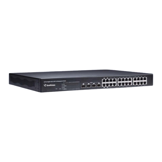
GV-POE2411
PoE Switch
24-Port Gigabit Ethernet with 4-Port Combo Gigabit SFP Web Management PoE Switch
Packing List
Before you start to install, please verify that your package contains the following items:
1. GV-POE2411 x 1
2. AC Power Cord x 1
3. Screw x 8
4. Rack Mount Kit x 1
5. User's Manual CD x 1
6. GV-POE2411 Quick Start Guide x 1
Note: If any of these items is found missing or damaged, please contact your local
supplier for replacement.
December 26, 2013
24-Port Gigabit 802.3at Web Management
1
Advertisement
Table of Contents

Related Manuals for GeoVision GV-POE2411


Summary of Contents for GeoVision GV-POE2411
- Page 1 3. Screw x 8 4. Rack Mount Kit x 1 5. User’s Manual CD x 1 6. GV-POE2411 Quick Start Guide x 1 Note: If any of these items is found missing or damaged, please contact your local supplier for replacement.
-
Page 2: Front Panel
Front Panel LED Display Gigabit SFP Gigabit RJ-45 Reset Button 24 Port Gigabit with 4 SFP PoE+ Management Switch 14 16 20 22 24 Combo LINK/ACT Power Reset LINK/ACT 13 15 21 23 IMPORTANT: The 4 SFP ports labeled F1 ~ F4 are associated with the 4 RJ-45 ports labeled 1 ~ 4 respectively. -
Page 3: Rear Panel
Rear Panel AC input (100~240 V/AC, 50~60 Hz) UL Safety Connection Connecting up to 23 GV-IP Cameras and 1 GV-NVR/DVR System Through twisted pair cables, this switch can be connected to up to 23 GV-IP Cameras and 1 GV-NVR/DVR System. You can also extend the connections by connecting to other switches. Note: The maximum cable length for Gigabit RJ-45 is 100 meters. -
Page 4: Web Interface
Web Interface Users can log in web interface to manage and set up the switch. Follow the below steps to log in the Web user interface. Note: The device has a default IP \\192.168.0.250. The default Password to log in is admin. 1. -
Page 5: Load Default Setting
Load Default Setting You can load the default value with the Rest button or with the Web interface. Hardware Follow the steps below to restore the switch to its default settings using the Reset button on the front panel of the switch. Note: After restoring default settings, you will need to configure IP address, ID and Password again. -
Page 6: Firmware Update
Firmware Update 1. On the Web interface, under Maintenance, select Software Upload. 2. When this page appears, click Browse to select the latest firmware file (.bin) to upload. 3. Click Upload. The uploading process starts. 4. After the firmware file is successfully uploaded, click Logout from the left menu and re- login the switch. -
Page 7: Specifications
Specifications Ports 24 ports Number of Ports 24-port 10/100/1000BaseTX with RJ-45 Connectors, PoE+ 4-port SFP Combo uplink Port Performance MAC Address Buffer Memory 4 M bits Jumbo Frames 9.6 KB Transmission Method Store and Forward 10/100BaseTX Cat. 5 UTP/STP Transmission Media 1000BaseT Cat. - Page 8 General Dimensions (H x W x D) 44 x 440 x 331 mm (1.73” x 17.3” x 13.03”) Weight 4.7 kg (10.36 lb) Operating Temperature 0°C ~ 40°C (32°F ~ 104°F) Storage Temperature -20°C ~ 90°C (-4°F ~ 194°F) Humidity 10% ~ 90% RH (non-condensing) Standards and Regulatory IEEE 802.3 10BaseT...
Need help?
Do you have a question about the GV-POE2411 and is the answer not in the manual?
Questions and answers