DCS RGS-305 Installation Manual
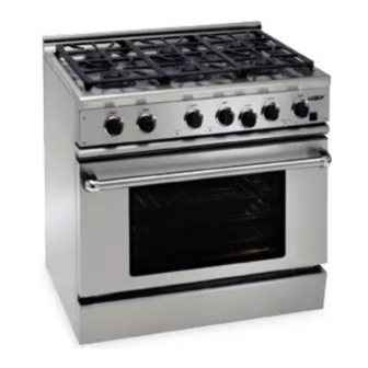
Rgs series range
Hide thumbs
Also See for RGS-305:
- Use and care manual (66 pages) ,
- Use and care manual (34 pages) ,
- Use and care manual (34 pages)

Subscribe to Our Youtube Channel
Related Manuals for DCS RGS-305


Summary of Contents for DCS RGS-305
- Page 1 RGS SERIES RANGE Installation Guide MODELS: RGS-305 RGS-484GG RGS-366 RGS-486GL RGS-364GL RGS-486GD RGS-364GD RGS-485GD...
- Page 2 A MESSAGE TO OUR CUSTOMERS Thank you for selecting this DCS RGS Gas Range. Because of this appliance’s unique features we have developed this Installation Guide. It contains valuable information on how to properly operate and maintain your new appliance for years of safe and enjoyable cooking.
-
Page 3: Table Of Contents
TABLE OF CONTENTS INTRODUCTION ..................................3 MODELS ....................................4 PLANNING THE INSTALLATION ..........................5 UNPACKING AND HANDLING ..........................5-7 VENTILATION REQUIREMENTS ..........................8 INSTALLING ANTI-TIP DEVICE ..........................9 CABINET PREPARATION ............................10-12 BACKGUARD INSTALLATION ..........................13 ELECTRICAL / GAS CONNECTIONS ......................13-14 TEST AND ADJUSTMENTS ..........................14-15 INSTALLER FINAL CHECKLIST .........................15-16 WIRING DIAGRAMS ..............................17-23... -
Page 4: Introduction
INTRODUCTION The DCS Professional series ranges are designed with a large number of features available in a multitude of different combinations. Top burner sections, thermostatic griddles, and grills are available as complete freestanding ranges. The large capacity gas convection ovens of the RGS series are equipped with an in-oven gas infrared broiler. -
Page 5: Models
MODELS 48” RGS RANGE MODELS RGS-484GG RGS-486GL RGS-486GD RGS-485GD 36” RGS RANGE MODELS RGS-366 RGS-364GL RGS-364GD 30” RGS RANGE MODELS OVEN ON HEATING HEATING DOOR LOCKED RGS-305... -
Page 6: Planning The Installation
PLANNING THE INSTALLATION RECOMMENDED INSTALLATION INSTRUCTION Install components in the following order: A) Vent Hood B) Backguard System C) Range 1) Locate and level range according to range installation instructions. 2) Measure distance from floor to top of island trim on range adding 1/8” for backguard clearance. 3) Transfer this measurement to the wall. - Page 7 With the doors and knobs removed, a 29 1/16” (RGS-36/48) or 29 3/8” (RGS-305) wide opening is required. Without removing the door, a 31 1/2”(RGS-36/48) or 30”(RGS- 305) wide opening is required. Remove the outer carton and packing material from the shipping base.
- Page 8 UNPACKING AND HANDLING After checking the countertops for level and Door Hinge Roller DOOR HINGE ROLLER before sliding the range into place, measure the distance from the floor to the top of the counter work surface in the rear left and right corners. Adjust the corresponding rear corner of the range to an equal height of the counter, as the rear leveling legs are not accessible once the range is...
-
Page 9: Ventilation Requirements
VENTILATION REQUIREMENTS STEP 2: A suitable exhaust hood must be installed above the range. The following chart indicates the minimum blower capacity recommended for hood ventilation. VENTILATION STANDARD COUNTER ISLAND UNIT INSTALLATION INSTALLATION RECOMMENDATIONS RECOMMENDATIONS HOOD (24" Deep x Unit Width) (30"... -
Page 10: Installing Anti-Tip Device
7/8” tip bracket to the floor and wall. The use of Model this bracket does not preclude tipping of RGS-48 RGS-305 RGS-36 Series the range when not properly installed. WOOD CONSTRUCTION: Place the bracket against the back wall, into the WARNING right rear corner where the range is to be located. -
Page 11: Cabinet Preparation
1) The range is a free standing unit. If the unit is to be placed adjacent to cabinets, the clearances shown in fig. 8 (RGS-48 & 36) & fig. 10 (RGS-305) are required. The same clearances apply to island installations. - Page 12 CABINET PREPARATION 12" Min. to Combustibles without backguard 36" Min. to Combustibles 0” Clearance 0” Clearance Fig. 9 RGS 48” & 36” Models Only WIDTH RGS 48 Models 28-1/8” 10-1/8” 2” 35 1/2” min.-37” max. 30-1/4” 44-1/2” 28-1/4” 1-5/16” 25” 27-3/8” 47-7/8” RGS 36 Models 28-1/8”...
- Page 13 CABINET PREPARATION Min. 30" Wide Hood 13" CAUTION: Max. 36" Min. to 12" Min. to combustible combustible material , each side material , 18" Min. from cooking 16 " 2 " surface cooking surface 4" Electrical and Gas Supply 35-3/8" Max. For Level Counter, 36-3/4"...
-
Page 14: Backguard Installation
Receptacle Box Cover Plate Cover Plate Power Requirements Range: 120 VAC, 60 Hz., single phase Three Prong Three RGS-305: 4 Amp. Max. Prong Plug Plug RGS-36: 7 Amp. Max. RGS-48: 13 Amp. Max. (use 15 Amp. circuit) Always disconnect electric supply cord from the wall outlet or service disconnect before servicing this appliance. - Page 15 ELECTRICAL / GAS CONNECTIONS GAS REQUIREMENTS Gas Supply Gas Supply Verify the type of gas supplied to the location. The Flex Line To Range Flex Line to Range range are shipped from the factory set up and Manual Shut-Off adjusted for natural gas or LP (propane), depending on Manual Shut-Off Valve Must Be Valve must be...
-
Page 16: Test And Adjustments
TEST AND ADJUSTMENTS STEP 6: CAUTION: For Warranty coverage, DCS requires that burner adjustments be made by a qualified technician at the time of installation. Extreme care should be used when adjustments are made after installation. Improper or lack of adjustments will void your warranty. -
Page 17: Installer Final Checklist
INSTALLER FINAL CHECKLIST GENERAL Placement of unit. Specified clearance maintained to cabinet surfaces. Unit Level - front to back, side to side. All packaging material and tie straps removed, drip pans clean and empty. Backguard attached if there is less than 12" clearance above the cooking surface to combustibles behind unit. -
Page 18: Wiring Diagrams
RGS-48 WIRING DIAGRAM... -
Page 19: Rgs 36"Wiring Diagram
RGS-36 WIRING DIAGRAM... -
Page 20: Rgs 36" / 48"Wiring Schematic
RGS-48/36 SCHEMATIC... -
Page 21: Rgs 485 Wiring Diagram
RGS-485 WIRING DIAGRAM... -
Page 22: Rgs 485 Wiring Schematic
RGS-485 SCHEMATIC... -
Page 23: Rgs 305 Wiring Diagram
RGS-305 WIRING DIAGRAM... -
Page 24: Rgs 305 Wiring Schematic
RGS-305 SCHEMATIC... -
Page 25: How To Obtain Service
HOW TO OBTAIN SERVICE For warranty service, contact DCS Customer Service at (888) 281-5698. Before you call, please have the following information ready: Model Number Serial Number Date of installation A brief description of the problem Your satisfaction is of the utmost importance to us. If a problem cannot be resolved to your... -
Page 26: Warranty
DCS to be defective. Replacement will be F.O.B. DCS, and DCS will not be liable for any transportation costs, labor costs, or export duties. This warranty shall not apply, nor can we assume responsibility for damage that might... - Page 27 NOTES...
- Page 28 NOTES...
- Page 29 NOTES...
- Page 30 5800 Skylab Road, Huntington Beach, CA 92647 Tel: 714.372.7000 • Fax: 714.372.7001 Customer Service: (888) 281-5698 www.dcsappliances.com As product improvement is an ongoing process at DCS, we reserve the right to change specifications or design without notice. P/N 17456 Rev. A...
Need help?
Do you have a question about the RGS-305 and is the answer not in the manual?
Questions and answers