Table of Contents
Advertisement
Quick Links
INSTALER:
Leave this manual with the appliance.
CONSUMER:
Retain this manual for future reference.
WARNING:
If the information in these
instructions is not followed exactly a fire or
explosion may result causing property
damage, personal injury or death.
FOR YOUR SAFETY
Do not store or use gasoline or other
flammable vapours and liquids in the vicinity
of this or any other appliance.
WHAT TO DO IF YOU SMELL GAS
Do not try to light any appliance.
Do not touch any electrical Switch.
Do not use any phone in your building.
Immediately call your gas supplier
from a neighbour's phone. Follow the
gas supplier's instructions.
If you cannot reach your gas supplier
call the fire department.
Installation and service must be performed
by a qualified installer, service agency or the
gas supplier.
This appliance may be installed in an
aftermarket permanently located,
manufactured home (USA only) or mobile
home, where not prohibited by local codes.
This appliance is only for use with the type of
gas indicated on the rating plate. This
appliance is not convertible for use with
other gases unless a certified kit is used.
This appliance is suitable for installation in a
bedroom or bed sitting room.
090314
33333
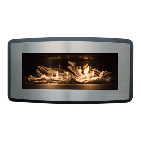
LINEAR GAS FIREPLACE
INSTALLATION AND
OPERATING INSTRUCTIONS
MODEL: ESPRIT
ESPR.BODYA
ZERO CLEARANCE FIREPLACE
ESPR.BODYA
5056.201
Advertisement
Table of Contents

Related Manuals for Pacific energy ESPRIT


Summary of Contents for Pacific energy ESPRIT
-
Page 1: Operating Instructions
This appliance is not convertible for use with other gases unless a certified kit is used. This appliance is suitable for installation in a MODEL: ESPRIT bedroom or bed sitting room. ESPR.BODYA ZERO CLEARANCE FIREPLACE 090314 ESPR.BODYA... -
Page 2: Important Note For The Commonwealth Of Massachusetts
Important Note for the Commonwealth of Massachusetts: From Massachusetts Rules and Regulations 248 CMR 5.08: For all side wall horizontally vented gas fuelled equipment installed in every dwelling, building or structure used in whole or in part for residential purposes, including those owned or operated by the Commonwealth and where the side wall exhaust vent termination is less than seven (7) feet above finished grade in the area of the venting, including but not limited to decks and porches, the following requirements shall be satisfied. -
Page 3: Table Of Contents
Table of Contents Caution Safety Owners Information First Fire Remote Control Operation Maintenance Lighting Instructions Installer information Fireplace Dimensions Clearances to Combustibles Locating the Fireplace Surround Installation Venting Venting Components Plumbing and Electrical Gas Supply Gas Pressure Check Gas Pressure Testing Procedure Pilot Adjustment Propane Conversion Door Installation / Removal... -
Page 4: Caution
Caution FOR YOUR SAFETY - Do not install or operate your Pacific Energy fireplace without first reading and understanding this manual. Any installation or operational deviation from the following instructions voids the Pacific Energy Warranty and may prove hazardous. This appliance and its individual shut off valve must be disconnected from gas supply piping system during any pressure testing of that system at test pressures in excess of 1/2 psi (3.5 kPa). -
Page 5: Safety
Safety Due to high temperatures, this gas appliance should be located out of traffic and away from furniture and draperies. Children and adults should be alerted to the hazards of high surface temperatures and should stay away to avoid burns or clothing ignition. ... -
Page 6: Owners Information
OWNER’S INFORMATION Congratulations on your purchase of a Pacific Energy Gas Fireplace. Your fireplace has been professionally installed by: Dealer name: ___________________ Phone Number: _________________ If you discover any problems with your gas fireplace contact your dealer immediately to have the unit repaired. -
Page 7: Remote Control Operation
OWNER’S Remote Control Operation INFORMATION Important The Proflame Transmitter is an integrated part of the Proflame System, which consists of: • Proflame Transmitter, to be used in conjunction with • Integrated Fireplaces Control (Proflame IFC) The Proflame Transmitter provides for controlling of the following hearth appliance functions: 1. - Page 8 OWNER’S INFORMATION Technical Data Remote Control Supply voltage 4.5 V (three AAA LR03 1.5 V batteries) Ambient temperature ratings 0 - 50 °C (32 - 122 °F) Typical operative distance in free air 12 m Radio frequency 315 MHz ( FCC version ) 433.92 MHz ( CE version ) WARNING THE TRANSMITTER AND RECEIVER ARE RADIO FREQUENCY DEVICES.
-
Page 9: Operating Procedure
OWNER’S INFORMATION Wall mounting The Proflame remote control is supplied with an adapter for wall mounting. Install the controller 1.5 m above floor level, well away from heat sources, kitchens, doors or windows. Metallic structures or radio interferences can reduce the operative distance of the device. Make sure to attach the adapter in a level plane without any distortion. - Page 10 OWNER’S INFORMATION Temperature indication Display With the system in the “OFF” position, press the Thermostat Key and the Mode Key at the same time. Look at the LCD screen on the transmitter to verify that a C or F is visible to the right of the Room Temperature display. (Fig.
- Page 11 OWNER’S INFORMATION ROOM THERMOSTAT (Transmitter Operation) The Remote Control can operate as a room thermostat. The thermostat can be set to a desired temperature to control the comfort level in a room. To activate this function, press the Thermostat key (Fig. 1). The LCD display on the transmitter will change to show that the room thermostat is “ON”...
- Page 12 OWNER’S INFORMATION Continuous Pilot/Intermittent Pilot (CPI/IPI) selection With the system in "OFF" position press the Mode Key (Fig. 1) to index to the CPI mode icon (fig. 13 & 14). Pressing the Up Arrow Key will activate the Continous Pilot Ignition mode (CPI). Pressing the Down Arrow Key will return to IPI.
- Page 13 OWNER’S INFORMATION KEY LOCK This function will lock the keys to avoid unsupervised operation. To activate this function, press the MODE and UP Keys at the same time (Fig. 21). To de-activate this function, press the MODE and UP Keys at the same time.
- Page 14 OWNER’S INFORMATION DIMENSIONAL DRAWINGS PROFLAME Transmitter dimensional drawing Fig. 23:...
-
Page 15: Maintenance
Do not strike or otherwise impact the glass in any way that may cause it to break. If the glass becomes cracked or broken it must be replaced before using the fireplace. Replacement door can be obtained from your nearest Pacific Energy dealer. Do not substitute with any other type. - Page 16 OWNER’S INFORMATION c) Check that the vent pipe and vent terminal are open and free from blockage or debris. The flow of combustion and ventilation air must not be obstructed. If the venting is disassembled for cleaning, it must be properly assembled and re-sealed. d) Check glass panel gasket, replace if necessary.
-
Page 17: Lighting Instructions
OWNER’S Lighting Instructions INFORMATION... -
Page 18: Installer Information
INSTALLER Fireplace Dimensions INFORMATION The installation must conform with local codes or, in the absence of local codes, with the National Fuel Gas Code, ANSI Z223.1/NFPA 54, or the National Gas and Propane Installation Code, CSA B149.1 A manufactured home (USA only) or mobile home OEM installation must conform with the Manufactured Home Construction and Safety Standard, Title 24 CFR, Part 3280, or, when such a standard is not applicable, the Standard for Manufactured Home Installations, ANSI/NCSBCS A225.1, or standard for Gas Equipped Recreational Vehicles... - Page 19 INSTALLER INFORMATION Fig. 26: Framing At The Corner Fig. 27: Minimum Clearance Corner Framing...
-
Page 20: Clearances To Combustibles
INSTALLER Clearances to Combustibles INFORMATION LEFT SIDE RIGHT SIDE FRONT Front of the appliance is an open side of the combustion chamber covered with the glass. Facing the front of the appliance side from left is the left side of the appliance and side from right is the right side of the appliance. -
Page 21: Locating The Fireplace
INSTALLER Locating the Fireplace INFORMATION In planning the installation for the fireplace, it is necessary to determine where the unit is to be installed, location of vent system and where gas supply piping may be plumbed. Various installations are possible, such as, into an existing wall, a corner, a built in wall or a wall projection. Due to high temperatures, do not locate this fireplace in areas of high traffic or near furniture or draperies. -
Page 22: Surround Installation
INSTALLER Surround Installation Instructions INFORMATION Figure 33: Clean Face Surround Figure 32: Louvered Surround Installation 1. Fasten the surround base to the fireplace using supplied screws and mounting holes located along the inner edge of the base. 2. Install screen with the frame in slots on inner side of the surround base. 3. -
Page 23: Venting
INSTALLER Venting INFORMATION Note: The intake damper positions specified in this chart were set in a controlled testing environment, and serve as a general guideline for installations. Every venting configuration is different, and the damper setting may need slight adjustment from this chart. - Page 24 INSTALLER INFORMATION This fireplace is certified for use with 4” x 6-5/8”coaxial venting components only. It is permitted to only use certified venting for this appliance.
-
Page 25: Venting Components
INSTALLER Venting Components INFORMATION NOTE: Mixing venting components from different manufacturers is inadvisable. Figure 35: 4”x6-5/8" Rigid Piping Cross Reference Chart Figure 1: 4”x6-5/8" Rigid Piping Cross Reference Chart Figure 36: 4”x6-5/8" Rigid Pipe Components Cross Reference Chart... -
Page 26: Plumbing And Electrical
INSTALLER Plumbing and Electrical INFORMATION Gas connection To make the required electrical and gas connections, start by positioning the gas fireplace. Connect the gas supply line to the 1/2” fitting that located on a shut off valve bracket as seen in Figure 37. A gas shut off valve is located inside the fireplace and may be accessed by removing the inner firebox unit. -
Page 27: Gas Supply
Turn on the gas supply and check that all connections are tight and leak free. WARNING: The gas tray including gasket must be reinstalled after conversion/installation or servicing has been completed. Gas Pressure Check Please refer to following page for gas pressure testing procedure. Gas pressure Esprit Gas Orifice Output AFUE requirements 2.55mm 30,000 btu/hr max. -
Page 28: Gas Pressure Testing Procedure
INSTALLER Gas Pressure Testing Procedure INFORMATION Note: To test the gas pressure, turn off the gas supply to the appliance before loosening test point screws. Verify gas pressures with the fireplace lit and at the highest setting. 1. Remove window surround and locate the valve as seen in Figure 38. 2. -
Page 29: Propane Conversion
INSTALLER Propane Conversion INFORMATION Before starting the conversion make sure to shut off the gas supply to the unit and allow fireplace to cool to room temperature. To convert the gas fireplace from natural gas to propane the kit is required. This kit comes with new pilot and burner orifices as well as a new pressure modulator for the valve. -
Page 30: Door Installation/Removal
INSTALLER Door Installation/Removal INFORMATION Installation 1. Place the door in the slot at the bottom of the firebox opening. 2. Hold the door against the firebox. Push 3 levers at the top of the door to secure the door. Removal 1. -
Page 31: Panel Installation/Removal
INSTALLER INFORMATION Fan removal before fireplace installation. 1. Remove fan panel at the rear side of the fireplace as seen in Figure 44. 2. Disconnect fan electrical wires and remove fan fasteners. 3. Remove fan out of the firebox assembly. Panel Installation / Removal Installation/Removal 1. -
Page 32: Burner And Tray Installation/Removal
INSTALLER Burner and Tray Installation / Removal INFORMATION Burner Tray Installation / Removal Installation Place the burner tray in the fireplace. Turn off main gas supply to unit and connect 3/8" flex tubing and power cord from inner firebox . Secure tray with screws placed around the perimeter of the tray using a screwdriver, as seen in Figure 49. -
Page 33: Log Set Installation/Removal
INSTALLER Log Set Installation / Removal INFORMATION Place the Logs #1 and #2 as seen in Fig.53 than place Log #3 over dowel pin on Log #2 as seen in Fig.54. Place Log #6 to the left side seen in Fig 55. Place side Log #5 and #4 as seen in Fig 56. -
Page 34: Glass Burner Kit Installation/Removal
INSTALLER Glass Burner Kit Installation / Removal INFORMATION Glass Installation To install the glass, evenly spread a thin layer of crushed glass across the entire burner pan as seen in Figure 67. To install the optional rock set, simply place desired number of rocks into the fireplace pan as seen in Figure 68 making sure no rocks are in the flame when the unit is operating. -
Page 35: Intake Air Damper Installation
Intake Air Damper Installation INFORMATION The Esprit fireplaces come with the damper that can limit the flow of intake air. This damper is located behind the air baffle at the top of the inner firebox. Sometimes on installations that involve vertical venting configurations over 23 feet in height, the intake air tends to accelerate down the vent causing hectic flame action. -
Page 36: Sales Codes
INSTALLER INFORMATION ESPRIT LINEAR GAS FIREPLACE SALES CODES UNIT ESPRIT LINEAR GAS FIREPLACE ........ESPR.BODYA REPLACEMENT PARTS ESPRIT REPLACEMENT DOOR WITH GLASS ....ESPR.DOORA ESPRIT REPLACEMENT SCREEN ........ESPR.SCRNA PROPANE CONVERSION KIT ..........GASC.LPKIT COMPLETE REPLACEMENT GAS TRAY ......ESPR.BRNTRAYA REPLACEMENT GAS VALVE .......... -
Page 37: Wiring Diagram
INSTALLER Wiring Diagram INFORMATION Caution: Label all wires prior to disconnection when servicing controls. Wiring errors can cause improper and dangerous operation. Verify proper operation after servicing. -
Page 38: Installation Notes
INSTALLER Installation Notes INFORMATION NOTES: __________________________________________________________________________________________________ __________________________________________________________________________________________________ __________________________________________________________________________________________________ __________________________________________________________________________________________________ __________________________________________________________________________________________________ __________________________________________________________________________________________________ __________________________________________________________________________________________________ __________________________________________________________________________________________________ __________________________________________________________________________________________________ __________________________________________________________________________________________________ __________________________________________________________________________________________________ __________________________________________________________________________________________________ __________________________________________________________________________________________________ __________________________________________________________________________________________________ __________________________________________________________________________________________________ __________________________________________________________________________________________________ __________________________________________________________________________________________________ __________________________________________________________________________________________________ __________________________________________________________________________________________________ __________________________________________________________________________________________________ __________________________________________________________________________________________________ __________________________________________________________________________________________________ __________________________________________________________________________________________________ __________________________________________________________________________________________________ __________________________________________________________________________________________________ __________________________________________________________________________________________________ __________________________________________________________________________________________________ __________________________________________________________________________________________________ __________________________________________________________________________________________________ __________________________________________________________________________________________________ __________________________________________________________________________________________________ __________________________________________________________________________________________________ __________________________________________________________________________________________________ __________________________________________________________________________________________________ __________________________________________________________________________________________________ __________________________________________________________________________________________________... - Page 39 INSTALLER INFORMATION...
- Page 40 Technical support: 1-250-748-1184 Web site: www. pacificenergy.net 2975 Allenby Rd., Duncan, BC V9l 6V8...
Need help?
Do you have a question about the ESPRIT and is the answer not in the manual?
Questions and answers