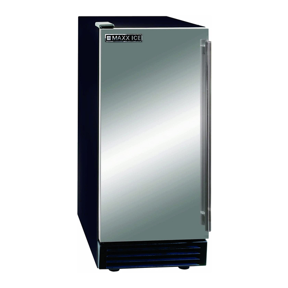
Maxx Ice MIM-50 Service Manual
Automatic ice maker
Hide thumbs
Also See for MIM-50:
- Instruction manual (27 pages) ,
- Service, installation, and instruction manual (60 pages) ,
- Instruction manual (71 pages)
Table of Contents
Advertisement
Advertisement
Table of Contents

Summary of Contents for Maxx Ice MIM-50
- Page 1 Automatic Ice Maker Service Manual MIM-50, MIM50-O...
-
Page 2: Table Of Contents
Table of contents How the Icemaker works ------------------------------------------------------------3-10 Cooling System -----------------------------------------------------------------3 Water System ----------------------------------------------------------------- 4-5 Wiring Connections and Controller------------------------------ ----------6-8 Exploding Drawing -----------------------------------------------------------9-10 TroubleShooting ------------------------------------------ --------------------------- 11-17 Before Maintenance-------------------------------------------------------------11 Basic Checking ------------------------------------------------------------------11 TroubleshootingGuide------------------------------------------------------ 12-17 Adjustment and Replacement----------------------------------------------------- 18-19 Replace the controller----------------------------------------------------------18 Replace the water pump-------------------------------------------------------18 Replace the compressor-------------------------------------------------------19 Replace the fan motor and fan blade------------------------------------ ----19... -
Page 3: How The Icemaker Works
How the Icemaker Works Please refer to the section “Operation of user manual” from page 13 to 16 . It describes clear how the icemaker makes ice and uses the water. There are 3 systems including Cooling System, Water System and Wiring Connection and Controller. -
Page 4: Water System
Fan blade 39.1 Temperature sensor of the condenser Discharge tube 39.2 Temperature sensor of the evaporator Wiring harness Evaporator (Ice Mold) Controllerbox During the ice-making stage, the hot gas solenoid valve is closed. The hot refrigerant gas is pumped out off compressor to condenser. The hot gas is cooled by fan forced air to warm liquid refrigerant after passing through the condenser. -
Page 5: Product View And Parts
NUMBER DESCRIPTION NUMBER DESCRIPTION Water pump Water pump inlet tube Water pump outlet tube Floater valve Water inlet Nut of water inlet tube Water inlet tube Water supply pipe Water distribution tube Evaporator Ice slideway Ice full probe Water trough Water trough drain tub... -
Page 6: Wiring Connections And Controller
Wiring Connection :... -
Page 7: Circuit Description
Circuit Description 1. Electrify Status For The First Time As the icemaker is properly installed. switch on the water tap, let the water trough full (reach on the level), then turn the ICE/OFF/WASH switch to the ICE position on the front panel. The icemaker will start working automatically In this status, the time is fixed about 3 minutes. -
Page 8: Major Functions
3. Yellow LED: Ice harvest indicator light. When this LED is lit, the unit is working in the ice harvest mode controlled by ice-full probe . When green LED and yellow LED is lit, it means the unit is working in the cold preservation stage . 4. -
Page 9: Exploding Drawing
Exploding Drawing... -
Page 10: Parts List
Item No. Part Number Description 1885000202 Condenser 1854703321 Hot gas valve coil(Zhongbao) 1854703310 Hot gas valve body (Zhongbao) 1880007500 Drier 1858421900 Compressor 1858460900 Starting ralay 1858451100 Protector 1858200601 Fan motor 549738100 Fan blade (φ200X28°) 1880014701 Left foot 1880014801 Right foot 1853703503 Wiring harness 1853113800... -
Page 11: Troubleshooting
Troubleshooting ELECTRICAL SHOCK HAZARD Disconnect Electrical Power Before Beginning Removal of Parts Before Maintenance 1. Check out the user if the user uses a 115 VAC, 60Hz. only 15ampere electrical supply, and have properly grounded, ensure the maintainer against electrical shock. 2. - Page 12 Proble Check Possible Cause Probable Correction part kinds point Plug icemaker Plug the icemaker in. unplugged. Socket Socket is damaged Check and replace Power The icemaker power Turn the icemaker power switch switch switch turns to OFF. to ICE. Fuse The fuse is blown.
- Page 13 Drainage Drainage tray on top of Drain off water by unscrewing tray on top the compressor is full lower drainage nut. of the compressor Problem Check Possible Cause Probable Correction kinds part point loose. Wiring Plug tightly, or replace. connects Be damaged.
- Page 14 2.Low production Problem Check part Possible Cause Probable Correction kinds or point Refrigerant Refrigerant leaks Recharge. partially Cooling The condenser may be Clean the condenser. System Condenser dirty. The ambient Check the ambient and air flow The ambient temperature is high or temperature too low The fan is dirty or...
- Page 15 The ambient Adjust ambient The ambient temperature is too temperature. Cubes are temperature high. too small The setting See the service manual "adjust Electronic temperature is high. the size of ice cubes" controller Refrigerant leaks Recharge. Refrigerant setting See the service manual "adjust Electronic temperature the size of ice cubes"...
- Page 16 Problem Check part Possible Cause Probable Correction kinds or point Earth line The earth line isn't in Please use the socket meeting the socket. the standard. The body Lines lines Adjust, reconnect /replace lines electrified creepage. Electric electric Replace this electric component component component.
- Page 17 The ice full probe is Ice full probe Repair or replace the probe tube broken or can not turn doesn't back normal position. The room temperature The room Make the temperature returns spray is out the stated range, temperature within the stated range. the water pump stop Hot gas valve The hot gas valve is...
-
Page 18: Adjustment And Replacement
Adjustment and Replacement Replace Controller, fuse and the sensor of temperature ELECTRICAL SHOCK HAZARD Disconnect Electrical Power Before Beginning Removal of Parts Remove the rear cover, front panel, Locate the Electronic controller, Pull out the sensors of temperature (one at the evaporator, another at the condenser). ... -
Page 19: Replace The Compressor
inlet tube of pump. Loosen the screws, replace a new one. Reverse the above step to reassemble. Replace the cooling system components Replace the condensing components, See Figure “cooling system” 1.Replace the compressor and the compressor kit (includes relay, thermal protect). ...


Need help?
Do you have a question about the MIM-50 and is the answer not in the manual?
Questions and answers
Which is the filter for the MIM50p?