
Subscribe to Our Youtube Channel
Related Manuals for Alfa Plam COMMO COMPACT


Summary of Contents for Alfa Plam COMMO COMPACT
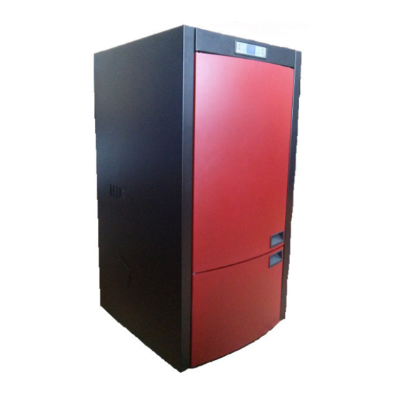
- Page 1 PELLET STOVE “COMMO COMPACT” INSTALLATION, OPERATION AND MAINTENANCE MANUAL Pellet → woody biomass → biofuel...
-
Page 2: Technical Characteristics Of The Stove
Any printing, translation and reproduction, even partial, of this Manual is subject to the approval of ALFA PLAM, which means that the said activities must be approved by ALFA PLAM. The technical information, figures and specifications in this Manual must not be provided to any third party. -
Page 3: The Purpose Of This Manual
1.1 UPDATING This Manual presents the state-of-the-art at the moment the stove is placed on the market. Therefore, ALFA PLAM does not take into account the stoves already on the market with appropriate technical documents, and considers them faulty or inadequate after any modifications, adaptations or application of new technologies to newly launched machines. -
Page 4: The Installation - Incorporation Of The Stove
− The type of the stove that is being installed, − Whether the room in which the stove is being installed is appropriate, which is expressed as the minimum size of the room required for the installation as prescribed by the stove manufacturer, −... -
Page 5: The Smoke Discharge System
− The flue pipe used by another heat generator (water heaters, stoves, fireplaces, kitchen stoves, etc.), − To the air exhaust system (grids, vents, etc.), even if the system is inserted in the pipe discharge. DANGER It is prohibited to install air circulation (draught) shut-off valves (flaps, valves that may prevent air circulation i.e. that may prevent draught). - Page 6 3. By the regulation of certain parameters in the stove. This regulation can be performed only by an authorized service centre of Alfa plam. − Ensure that the connection for the house chimney is properly sealed.
-
Page 7: The Insulation And Diameter Of The Openings (Holes) On The Roof (Or On The Wall)
Figure 3 3.3 THE INSULATION and DIAMETER OF THE OPENINGS (Holes) ON THE ROOF (or on the Wall) Once the position of the stove is determined, it is necessary to make a hole i.e. an opening the flue pipe should pass through. - Page 8 1. T-shaped pipe fittings – T-shaped pipe coupling 2. Cleaning direction 3. Opening, window for servicing / inspection 4. Cleaning direction 5. T-shaped pipe fittings – T-shaped pipe coupling 6. Cleaning direction 7. Sealed cover for the purpose of cleaning (plug) S M E R D I M A Figure 7.Flue pipe installation...
-
Page 9: The Intake Of Combustion Air
Table 2: Insulation thickness for the part of the system that passes through wall or roof First of all, it is necessary to provide PERFECT CIRCULATION of air (draught) in the flue pipe which must be free of any obstacles such as narrowing or angles. Any shifts of the axis must have one path inclined with a maximum angle of 45 degrees from the vertical, and the best solution is 30 degrees. -
Page 10: Important Instructions
under the door, window, flue pipe, air chambers, etc. horizontally from 0.3 m above away from smoke outlet Table 4: Minimum distances for the intakes of combustion air 3.5 CONNECTION TO THE ELECTRIC POWER SUPPLY These stoves should be connected to the electric power supply. Our stoves have electric cables suitable for medium temperatures. -
Page 11: Warning Of The Safety Measures For The User
Besides being obliged to adhere to all safety measures, maintenance workers must: − Always use security devices and personal protective equipment. − Turn off the electric power supply before they start working. − Always use adequate tools. − Ensure that the stove and ash are completely cool before starting any operations on the stove. Especially, take care that the handles are cool before you touch them. -
Page 12: Routine Cleaning And Maintenance Performed By The User Of The Stove
− Remove ashes with a vacuum cleaner only when the stove is completely cool, − Never clean the stove surfaces with any abrasive cleaning agents. 6.1 ROUTINE CLEANING and MAINTENANCE PERFORMED BY THE USER OF THE STOVE The use of a drum-shaped vacuum cleaner can facilitate the stove cleaning. The vacuum cleaner must have a filter which stops the vacuumed dust to go back into the room where the stove is located. - Page 13 Figure 12 Figure 13 In this manner all dirt that stays inside during the combustion of pellets will be removed. Then the ash box must be properly returned to its position. Do not ever put pellets that have not burnt down in the ashtray or ash box. The lower ash box must be cleaned once in fifteen –...
- Page 14 Figure 16 Perform cleaning when the stove is cold. After cleaning the button should always be returned completely inwards so that only the button would be visible, and not the bar from the cleaning mechanism. See figure 16. Use a vacuum cleaner to vacuum the ashes at the door opening, behind the glass. -DOOR WITH GLASS (the door should be checked and cleaned from time to time): The stove and ash must be completely cool.
-
Page 15: Special Maintenance
should preferably contact authorized professionals. The spots that should be paid special attention to during cleaning and that should be cleaned particularly well are shown in Figure 18. − INNER FIREBOX (every two weeks) The stove and ash must be completely cool. Figure 18.Spots to be cleaned at least twice a year 6.3 SPECIAL MAINTENANCE Your stove is a heat generator that uses pellets as solid biofuel. -
Page 16: Connection Of The Hydraulic Installation
ONLY, and in accordance with the present legislation of the country in which the installation is performed. ALFA PLAM disclaims any responsibility in case of material or physical damage, or in case of malfunction, if the above-mentioned recommendation were not implemented. -
Page 17: Pressure Line And Return Duct
Figure 19 -Pos. water outlet is connection with external thread R1’’ for pressure line, -Pos. pipe of return water is connection with external thread R 1’’ for return duct, 10. PRESSURE LINE AND RETURN DUCT Pressure line and return duct outlets on the boiler are 1’’ wide and they should not be reduced or constricted before first forking. -
Page 18: Expansion Tank
Valve safety cap should be loose, not too tight, so that the air could freely leave the boiler and remain of installation. 11.4. EXPANSION TANK Furnace has built-in expansion tank with 10l volume. Function of the tank is pressure stabilisation in the boiler and in the heating system installation. -
Page 19: Operation Mode
Buttons: 1 – increase of the temperature and the program functions for changing the date and time 2 – reduction of the temperature and the program functions for changing the date and time 3 – change of the program SET 4 –... - Page 20 Figure 22 In order to ignite the stove, keep the button 4 pressed for few seconds, immediately after this we will get a START message on the display (figure 23) – we have started the stove. Figure 23 Immediately after this we get the message LIGHTER WAIT (figure 24) – the lighter ignites and immediately after this the message LOAD PELLET appears (figure 25) –...
- Page 21 Figure 28 15.2.2 Failed ignition Once a period of 20 minutes runs out, if the temperature of smoke did not reach the minimally allowed value of 45ºC, the stove transfers to the state of an alarm, see point 15.6.3. 15.2.3 Stove in operational mode If the stage of ignition is positively done i.e.
-
Page 22: Menu
When during the stage of ignition, the stove transfers to the stage of normal operation (stage WORK), it is possible to adjust the output power, that is, the intensity of heating. By pressing the buttons 5 and 6, the message SET OUTPUT appears, which means setting the output power. - Page 23 The button 6 is used for transition to the previous submenu and the adjusted settings are memorized. The button 5 is used for transition to the next submenu and the adjusted settings are memorized. The button 4 is used for transition to higher menu level, and the adjusted settings are memorized.
- Page 24 Figure 40 NEnu 01 YEAR CLOCK Figure 41 15.4.3. Menu 02 – programming of the stove operation There are three types of programming of the stove operation: Daily programming Weekly programming Weekend programming Daily programming This enables setting of the daily functions of the chronothermostat. The stove can be ignited and switched off twice as desired and this is regulated by programming, having in mind that sufficient time is required between the switching off and the new ignition so that the stove could cool.
- Page 25 N-2-2 PROGRAM Figure 46 Press the button SET twice and the representation on the display will be the same as in figure 47. The buttons 1 or 2 are used for adjusting the time of the first ignition of the stove during the day. By pressing the button SET, the display will have the same appearance as in figure 48 and the time of the first switching off of the stove is set by pressing the buttons 1 or 2.
- Page 26 N-2-3 PROGRAM WEEK Figure 51 Press the button SET and then the button 1 and activate the weekly programming (On) as shown in figure 49. N-2-3- 01 CHRONO WEEKLY Figure 52 By pressing the button SET and then the button 1 we are setting the starting time of the stove operation in the first program, as shown in figure 50.
- Page 27 Weekend programming The weekend programming enables programming, switching on and switching off of the stove (twice a day) during the weekends (Saturday and Sunday). Activate the weekend programming only if the daily and weekly programming has been deactivated. The first four steps during programming are the same as in the daily programming (figures 42-45). Press button 4 and then press button 5 three times and the display will look the same as shown in figure 57.
-
Page 28: Alarms
After these adjustments, we return to the main menu by pressing the button 4. SUGESTION: to avoid confusion and unwanted turning on and off, activate only one program if you are not sure what do you want to accomplish. Deactivate daily if you wish to engage weekly program. Weekend program always keep inactive, if using weekly program in levels 1, 2, 3 and 4. - Page 29 After every alarm sounding, furnace automatically shuts down Alarm is activated after 30 seconds and pressing the push-button P4 stops it. 15.5.1. Smoke temperature probe alarm It activates in case of smoke probe malfunction. During alarm, furnace automatically shuts down. 12:42 22ºC PROBE...
- Page 30 12:42 22ºC SAFETY THERMAL Figure 65 Figure 68 Boiler overheating alarm or screw feeder temperature: this alarm activates when the boiler temperature or screw feeder temperature is too high, and then message "SAFETY THERMAL" appears. This is additional safety device. To return to normal working mode, you should wait for furnace to shuts down (smoke fan works).
-
Page 31: Connection Scheme
18.5ºC 55 BLACK Figure 72 07:37 18.5ºC 55 CLEANING FINAL Figure 73 In order to cancel the alarm, it is necessarily to hold the button 4 pressed for about 2 seconds and the smoke motor transfers to a higher speed and the following message appears on the display (figure 73). After finishing that process, the display will show the indication as in figure 74 and the stove will be ready for new start. -
Page 32: Security Measures
16. SECURITY MEASURES Furnace is equipped with following safety devices: -PRESSURE REGULATOR Controls the pressure in the chimney. It stops transport spiral for the pellet when the outlet is clogged or when it faces pressure (draught) -FLUE GASES TEMPERATURE SENSOR Measures the temperature of the flue gasses and allows furnace ignition o stops it if the flue gasses temperature goes bellow set value. -
Page 33: Time Of Guaranteed Servicing
layer of sediment in 2. Wet or inadequate wood pellets. check if all openings are open. combustion 3. Smoke fan system motor is Clean chimney as well. Check if chamber. Hatch broken. the air intake is not clogged. Check glass is soiled and sealing cord on the hatch. -
Page 34: Table Of Contents
The guarantee is not valid for the glass, the glass-ceramic panel and the physical damages that have occurred after purchase. THE MANUFACTURER RETAINS ALL THE RIGHTS TO MAKE CHANGES. The device will properly function within the guaranteed term only if it is used in accordance with these guidelines for connection and application. - Page 35 15.4. Menu 15.5. Alarms 15.6. Connection scheme 16.0. Security measures 17.0. Malfunctions – causes – solutions 18.0 Information on the Disposal (Discarding) and Disassembly of the Stove 19.0 Time of guaranteed servicing...
Need help?
Do you have a question about the COMMO COMPACT and is the answer not in the manual?
Questions and answers