
Related Manuals for Sam4s ER-280 SERIES


Summary of Contents for Sam4s ER-280 SERIES
- Page 1 ELECTRONIC CASH REGISTER ER-280 SERIES SERVICE Manual ELECTRONIC CASH REGISTER C O N T E N T S Precaution Statements Product Specifications Installation and Operation Disassembly and Assembly Troubleshooting Exploded Views and Parts List PCB Layout and Parts List Block diagram Wiring Diagram 10.
- Page 2 About this Manual This service manual describes how to perform hardware service maintenance for the SAM4S ER-280 Series Electronic Cash Register. Notes Notes may appear anywhere in the manual. They describe additional information about the item. Precaution symbols . Indicates a Safety Precaution that applies to this part component.
- Page 3 This manual may not, in whole or in part, be copied, photocopied, reproduced, translated or converted to any electronic or machine readable from without prior written permission of Shin Heung Precision . SAM4S ER-280 SERIES Service Manual First edition. March 2007. V1.0 Printed in KOREA...
- Page 4 Overview of this ECR This ECR is a microprocessor-based system, using a 16 bits microprocessor. This service manual provides the technical information for many individual component systems, circuits and gives an analysis of the operations performed by the circuits. If you need more technical information, please contact our service branch or R&D center.
-
Page 5: Precaution Statements
Remplacer uniquement avec une batterie du même recommended by the manufacturer. type ou d’un type équivalent recommandé par le Dispose used batteries according to the constructeur. manufacturer’s instructions. Mettre au rebut les batteries usagées conformément aux instructions du fabricant. SAM4S ER-280 SERIES... - Page 6 4. Do not use freon-propelled chemicals. These can carpeted floor can generate enough static generate electrical charges that damage ESDs. electricity to damage an ESD. 5. Use only a grounded-tip soldering iron when soldering or unsoldering ESDs. SAM4S ER-280 SERIES...
-
Page 7: Product Specifications
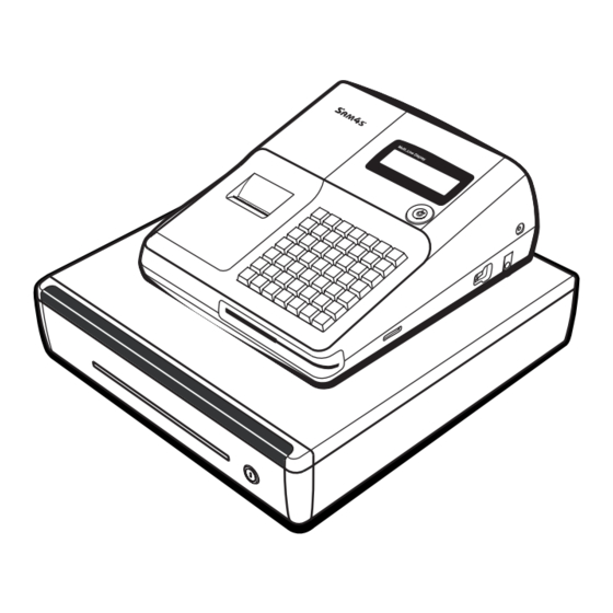
• Operator Display : 10 Digits VFD or LCD(16 * 2Line Character Type) Display • Customer Display : 10 Digits VFD • 49-Key (Raised Type): ER-280 Series Keyboard • 49-Key (Flat Type) : ER-285 Series • 5B5C / 4B8C Drawer Aplus-DRAWER •... - Page 8 ② Key Board (Raised or Flat type) ③ Drawer ④ Customer 10-Digits VFD Display ⑤ Operator Display (10-Digits VFD) or 16x2 line LCD ⑥ Mode Key ⑦ Interface Cover ⑧ SD-Card (Option) ⑨ MSR (Option) Figure2-2 Location Feature SAM4S ER-280 SERIES...
- Page 9 • 8(W) × 17(H) Font (Including a horizontal) Character Structure • 1.33 mm(W) ×2.83 mm(H) Character Size • 1.5 mm Column Pitch • 3.67 mm (Including 5-dot line spacing) Line Pitch • 32 (8×17 Dots/Character) Number of Column Table 2-4 Character Specification SAM4S ER-280 SERIES...
- Page 10 ② SPACE(Logic0) : The host can not receive a data ③ The ECR transmits a data to the host or receipt printer, after confirming this signal. Output VCC(+5V/150mA) is supplied at 9Pin of D-SUB Connector. *Caution* Table2-7 RS-232C Signal Description SAM4S ER-280 SERIES...
- Page 11 When DTR/DSR flow control is select, before transmitting a data, the ECR checks whether the host is BUSY or not. If the host is BUSY, ECR does not transmit a data to the host. If the host is not BUSY, ECR transmits a data to the Host. The host is the same. SAM4S ER-280 SERIES...
- Page 12 2. Product Specifications 2-5 Interface Specification 2-5-1-5 Cable Connection (DSUB 9 PIN FEMALE TYPE) & ) Figure2-3 RS232C Cable Connection (9Pin to 9Pin) & ) Figure2-4 RS232C Cable Connection (9Pin to 25Pin) SAM4S ER-280 SERIES...
- Page 13 4(DTR) 7(S.GND) 5(S.GND) 8(DTR) 6(DSR) 5(RTS) 7(RTS) 6(CTS) 8(CTS) Figure2-5 RS232C Cable Connection (RJ-11 to 9Pin) 4(RXD) 3(RXD) 3(TXD) 2(TXD) 2(DSR) 20(DTR) 7(S.GND) 7(S.GND) 8(DTR) 6(DSR) 5(RTS) 4(RTS) 6(CTS) 5(CTS) Figure2-6 RS232C Cable Connection (RJ-11 to 25Pin) SAM4S ER-280 SERIES...
-
Page 14: Usb Interface
• Connector : B type • USB Spec Version 1.1 Support Spec Table 2-9 USB Specification 2-5-1-5 Cable Connection PRINTER HOST SIDE SIDE "B" TYPE PLUG "A" TYPE PLUG ( USB I/F CABLE ) Figure2-7 USB Cable Connection SAM4S ER-280 SERIES... -
Page 15: Installation And Operation
3 Installation and Operation 3-1 System Configuration 3-1-1 Configuration Figure 3-1. System Configuration SAM4S ER-280 SERIES... - Page 16 3-2 (B)) 3. Insert the end of the paper into the paper slot.(Fig 3-2 (C)) 4. Close the paper lever. ( ER-280 Series is possible to feed automatically when you rock the paper levers insert paper.). (Fig 3-2 (D)) 5.
- Page 17 Wind the paper two or three turns around the spool shaft and install the spool in the mount 1. If you use the ER-280 Series with 1-station, refer to below figure. (Fig 3-3 (F)) 2. If you use the ER-280 Series with 2-stations, refer to below figure. (Fig 3-3 (G)) Figure 3-3.
- Page 18 3-2-5 Supplies Item Description Remark Paper Roll 1 EA VD, REG, X, Z, P, C : NON FISCAL Mode Key REG, X, Z, P, C : FISCAL User Manual 1 EA Spool 1 EA Table 3-2. Supplies SAM4S ER-280 SERIES...
-
Page 19: Mode Switch
Off, Register(REG), Manager(X), Clear Totals(Z) Void, Off, Register(REG), Manager(X), Clear Totals(Z), Program(P) Void, Off, Register(REG), Manager(X), Clear Totals(Z), Program(P), Service Mode(S) Table3-4 Key Function Note : The Key can be removed from the key lock in the OFF or REGISTER position. SAM4S ER-280 SERIES... - Page 20 3. Installation and Operation 3-3 Operation 3-3-2 Key Board Matrix 1) 1-station model Figure 3-6. 1-Station Model Key Board 2) 2-station model Figure 3-7. 2-Station Model Key Board SAM4S ER-280 SERIES...
- Page 21 4. While continuing to hold the “CASH” key, plug the register into a power source. 5. The message "****** INITIAL CLEAR ******” prints when the initial clear is complete. ****** INITIAL CLEAR OK ! ****** Figure3-8. Initial Clear Key & Print Sheet(ER-280) SAM4S ER-280 SERIES...
- Page 22 ************************************************** RAM ALL CLEAR OK ! ************************************************** ER-280 EPROM INFO. VERSION : STD CHECKSUM :5536 BOOT/APP :4745/0dF1 SEP 08 2006 CLERK 00 000001 00000 Figure3-9. All Clear Key Sequence & Print Sheet SAM4S ER-280 SERIES...
-
Page 23: Self Test
2. Press Press ‘1’, ‘4’ and ‘SUB TOTAL’ key on key board. 3. If error occurs, the message (232 NOGOOD) is displayed on VFD and the Buzzer beep. Then Press “Clear” key. Note : When the ports is unconnected the cable , the Error occur. SAM4S ER-280 SERIES... - Page 24 3. Installation and Operation MEMO 3-10 SAM4S ER-280 SERIES...
-
Page 25: Disassembly And Assembly
2. Separate the JOURNAL PRINTER(B5) & HARNESS GND(B38), REAR LEVER-LOCK(B4). (Page6-3) 3. Separate the harness(ⓓ) from the PBA-JOURNAL(B28). (Page6-3) 4. Remove the two screws(B29) and Separate the PBA-JOURNAL(B28) from the ASS’Y CASE UPPER (B). (Page6-3) 5. Separate the harness(ⓒ) from the PBA-JOURNAL(B28) . (Page6-3) SAM4S ER-280 SERIES... - Page 26 4-1-7 Ass’y Keyboard ⓑ ⓑ ⓜ) from the SWITCH-ROTARY(B30) & PBA MAIN(E17)(Page6-3) 1. Separate the three harnesses( , , 2. Remove the four screws(B37) and Separate the ASS’Y KEYBOARD(B35 or B36) from the ASS’Y CASE UPPER (B). (Page6-3) SAM4S ER-280 SERIES...
- Page 27 3. Separate the harness (ⓗ) and Remove the three screws(E12). (page6-8) 4. Lift up the I/F PBA(E13).(page6-8) 4-2-2 Ass’y Trans Power ⓤ ⓟ) and Remove the two screws(E14). (page6-8) 1. Separate the harnesses( , 2. Lift up the TRANS-POWER (E15) from the CASE LOWER(E24).(page6-8) SAM4S ER-280 SERIES...
- Page 28 4-3-2 Disassembly of the Window Rear ① Be sure to separate the ASS’Y CASE UPPER from the ASS’Y CASE LOWER. ② Pull the WINDOW REAR out as the Fig-2 carefully not to break the four ribs. Fig-2 SAM4S ER-280 SERIES...
- Page 29 4-3-3 Disassembly of the Rear VFD PCB ① Be sure to separate the ASS’Y CASE UPPER from the ASS’Y CASE LOWER. ② pull out in the direction of the Fig-3 to separate the REAR VFD PCB from the ASS’Y CASE UPPER. Fig-3 SAM4S ER-280 SERIES...
- Page 30 4. Disassembly and Assembly MEMO SAM4S ER-280 SERIES...
- Page 31 Power VCC 2. Check the TR KSA1010(Q16) (+5V) Ok? 3. Check the VCC whether it is short or open. 1. Check the LD1117(U26) Power VDD 2. Check the VDD 3.3V whether it is short or open. (+3.3V) Ok? SAM4S ER-280 SERIES...
- Page 32 4. Replace the RTC(PCF8563) SD CARD 1. Check the CS_SD CARD, nRD, nWR signal of SD (U27) 2. Check the clock (SD_Xiin : 7.3728MHz) 3. Check the mounted state circuit of SD pin whether pin is open or short SAM4S ER-280 SERIES...
- Page 33 2. Check the regulator AME8807(U31) and related Circuit. 3. Check the LCD harness and soldering status. 1. Check the LCD EN, LCD RS Signal. LCD Diaplay 2. Check the buffer 74HCT245(U25) and related Circuit. 3. Check the LCD harness and soldering status. SAM4S ER-280 SERIES...
- Page 34 (Clk / Data / Latch / Strobe#1/#2) 2. Check the VPH voltage. It is +8.0V 3. Check the VPH ON/OFF circuit and pattern. 4. Check the JOINT PCB and FFC harness. 5. Check and Replace the printer. SAM4S ER-280 SERIES...
- Page 35 2. Check the Matrix Bus & Data Bus Failure? 3. Check the Diodes(BAT43WS *7EA) 4. Check the Key Board Assy 1. Check the Mode Key Assy Mode Key 2. Check the Diode (D19) 3. Check the 74HC138(U19) & Data Bus SAM4S ER-280 SERIES...
- Page 36 2. Check the Micro switch in the Drawer. Failure? Spool Motor Problem 1. Check the Spool Motor Signal(CPU P6.0). Spool Motor 2. Check the VFD Display harness and Motor harness. 3. Check the related Circuit and pattern on Main B’D. SAM4S ER-280 SERIES...
- Page 37 6. Check the USB Driving Chip and related Circuit on Main B’D. Communication 1. Check the connection of the USB and Other side. 2. Check the USB Version. This Product supports USB 1.1 Version. 3. Check whether Signal is affected by the Cable Noise. SAM4S ER-280 SERIES...
- Page 38 3. Check the related Circuit and pattern on Main B’D. SD Problem 1. Perform the MCR test at H/W test mode. 2. Check the clock (SD_Xiin : 7.3728MHz) SD Read 3. Check the mounted state circuit of SD pin whether pin is open or short SAM4S ER-280 SERIES...
- Page 39 6 Exploded Views and Parts List 6-1 Main Set [ Exploded View ] Figure6-1 Total Disassembly SAM4S ER-280 SERIES...
- Page 40 A. ASS’Y COVER-PRINTER Figure 6-2. ASS’Y COVER-PRINTER 6.1. A. ASS’Y COVER-PRINTER Code No. Description/ Specification Q`ty Design-Location Serviceable Remark JK97-20056C MEA COVER-PRINTER:ER-280 IVORY JK72-20225C PMO-COVER PRINTER JK70-10320A IPR-CUTTER PAPER JK97-20056D MEA COVER-PRINTER:ER-280B BLACK JK72-20225D PMO-COVER PRINTER JK70-10320A IPR-CUTTER PAPER SAM4S ER-280 SERIES...
- Page 41 6. Exploded Views and Parts List 6-1 Main Set B. ASS’Y CASE-UPPER Figure 6-3. ASS’Y CASE-UPPER SAM4S ER-280 SERIES...
- Page 42 PBA DISPLAY:REAR ONLY LCD MODEL ER-280M JK92-01476A PBA DISPLAY:FRONT&REAR VFD MODEL ER-280 JK96-01080E LCD ASS'Y: 2 LINE JK59-30028A UNIT-KEYBOARD: 49KEY,RAISED ER-280 JK59-30029A UNIT-KEYBOARD:49KEY,FLAT ER-285 6002-000319 SCREW-TAPPING:PH,+,2,M3,L8 JK70-50029A SCREW-TAPPING:PWH,M3,L6,Ø10 JK68-40073A LABEL(R ) LCD SHEET LCD MODEL 6003-000198 SCREW-TAPPING:PWH,+,2,M3,L12 SAM4S ER-280 SERIES...
- Page 43 6. Exploded Views and Parts List 6-1 Main Set C. ASS’Y KEY BOARD(RAISED, 49KEY) Figure 6-4. ASS’Y KEY BOARD(RAISED) SAM4S ER-280 SERIES...
- Page 44 JK81-20057H KEY CAP_1X1 JK81-20057G KEY TOP_1X1:BLACK JK81-20057GW KEY TOP_1X1: IVORY JK81-20061A RETURN-SPRING JK81-20057C KEY CAP_2X1 JK81-20057B KEY TOP_2X1(VERTICAL):BLACK JK81-20057BW KEY TOP_2X1(VERTICAL): IVORY JK81-20050A PMO KBD FRAME_49,RAISED JK81-20050D CONTACT RUBBER_49,RAISED JK81-20050C ASSY-FPC_49,RAISED JK81-20050B IPR BOTTOM PLATE_49,RAISED JK81-20058A SCREW-TAPPING:BH,2.6X6 SAM4S ER-280 SERIES...
- Page 45 Figure 6-5. ASS’Y KEY BOARD(FLAT) D. ASS’Y KEY BOARD(FLAT, 49KEY) Code No. Description/ Specification Q`ty Serviceable Remark Design-Location JK59-30029A UNIT-KEYBOARD JK73-20219A WATER-PROOF JK68-40076A LABEL(P)- KEYBOARD SHEET ENGLISH(STD) JK81-20009B PMO-KBD HOUSING JK81-20012A KEY-RUBBER,49KEY,FLAT JK81-20051A ASSY-FPC,49KEY,FLAT JK81-20011B KBD-FRAME JK81-20058A SCREW-TAPPING:BH,2.6X6 SAM4S ER-280 SERIES...
- Page 46 6. Exploded Views and Parts List 6-1 Main Set E. ASS’Y CASE-LOWER Figure 6-6. ASS’Y CASE-LOWER SAM4S ER-280 SERIES...
- Page 47 FISCAL JK92-01284D PBA SUB-FISCAL:2MBIT,34P FISCAL JK72-40205A PMO-CASE FISCAL BOARD FISCAL JK72-20229A PMO-COVER MSR IVORY JK72-20229B PMO-COVER MSR BLACK JK48-00005A MCR:MSR-1160-SH,TRACK2-3 JK48-00006A MCR:MSR-1150-SH,TRACK1-2 6002-000319 SCREW-TAPPING;PH,M3,L8 JK60-00001A SCREW-ASSY TAPTITE:M3,L8 6002-000174 SCREW-TAPPING:PWH,M3,L10 JK39-40687A HARNESS I/F:6P JK92-01473A PBA I/F:ER-260,232*1 1 SERIAL SAM4S ER-280 SERIES...
- Page 48 6. Exploded Views and Parts List 6-2 DRAWER F. ASS’Y DRAWER Figure 6-7. ASS’Y DRAWER 6-10 SAM4S ER-280 SERIES...
- Page 49 6. Exploded Views and Parts List 6-2 DRAWER F. ASS’Y DRAWER Figure 6-8. Lubrication Points of the Drawer SAM4S ER-280 SERIES 6-11...
-
Page 50: Exploded Views And Parts List
IPR-HOUSING DRAWER : STD WHITE JK70-20062B IPR-HOUSING DRAWER : STD BLACK JK70-20062C IPR-HOUSING DRAWER : SER WHITE JK70-20062D IPR-HOUSING DRAWER : SER BLACK JK70-20062E IPR-HOUSING DRAWER : IMPER WHITE JK70-20062F IPR-HOUSING DRAWER : IMPER BLACK JK70-50070A SCREW-TAPTITE : BLACK 6-12 SAM4S ER-280 SERIES... - Page 51 AS-RAIL OUTER LH 5B5C JK72-20255A PMO-COVER BOTTOM WHITE JK72-20255B PMO-COVER BOTTOM BLACK JK61-40201A FOOT JK81-20064A AS-RAIL OUTER RH 4B8C JK81-20064B AS-RAIL OUTER RH 5B5C 6003-000267 SCREW-TAPTITE : PWH,M3,L8 JK39-40689A HARNESS-DRAWER COMPULSORY Jk70-50073A SCREW-DELTA PT:BH,M3,L8,PI5.5,WHITE Jk70-50073B SCREW-DELTA PT:BH,M3,L8,PI5.5,BLACK SAM4S ER-280 SERIES 6-13...
- Page 52 1SET JK70-20075D IPR-KEY DRAWER : KEY NO.3355 1SET JK70-20075E IPR-KEY DRAWER : KEY NO.4224 1SET JK70-20075F IPR-KEY DRAWER : KEY NO.4242 1SET JK70-20075G IPR-KEY DRAWER : KEY NO.5355 1SET JK70-20075H IPR-KEY DRAWER : KEY NO.5535 1SET 6-14 SAM4S ER-280 SERIES...
-
Page 53: Pcb Layout And Parts List
7 PCB Layout and Parts List 7-1 Main PCB SAM4S ER-280 SERIES... - Page 54 CN6,CN7 3708-001395 CONNECTOR-FPC/FFC/PIC:30P,1mm,ST,DIP,TOP 3711-000242 CONNECTOR-HEADER:1WALL,4P,1R,3.96mm,ST 3711-002002 CONNECTOR-HEADER:BOX,22P,2R,2mm,ST,BLK CN5,CN13 3711-004100 WAFER;BOX-HEADER,1R,2P,2.5mm,ST,WHITE, CN10 3711-004105 WAFER;BOX-HEADER,1R,4P,2.5mm,ST,WHITE, CN12 4301-000121 BATTERY:3.0V,11mAh,MS920S-FL27E BAT1 KSA1010Y+HS1, 6002-000175 SCREW-TAPPING:PWH,+,2,M3,L8,ZPC(YEL) KSA1010Y+HS2 6203-000108 HEAT SINK:NONE,T3,W10.5,L15,H30,AL,YS100 HS1,HS2 JC68-10564A LABEL(P)-PROTECTOR:SLB-3108H,ART,-,100(S ROM VER. JK27-60100D COIL-FILTER:140uH,0.2Ω,8.5*17*17,TR15Φ L1,L2 JK39-40541A CBF HARNESS-GND:ER-5100II,UL1015#18,260 GND WIRE SAM4S ER-280 SERIES...
- Page 55 IC-HOST I/F SD/MMC:W86L388-DG,LQFP,48P 1106-000246 IC-SRAM:BS62LV4006,512Kx8BIT,SOP,32P,4M 1107-001121 IC-FLASH MEMORY:1M*8BIT/512K*16BIT,8M,5V 1202-000164 IC-VOLTAGE COMPARATOR:KA393,SOP,8P,1.27m U9,U30 1203-000404 IC-DC/DC CONVERTER:34063,SOP,8P,150MIL,P U16,U22 1203-000501 IC-RESET:AME8500CEETBE42,SOT-23,3P,5V 1203-001765 IC-REGULATOR;AME8807AEHA,SOP,8P 1203-001770 IC-REGULATOR;AME1117(ADJ),SOT-223,4P R7,R12,R60,R64,R82,R92, 2008-000008 R-CHIP:100OHM,5%,1/10W,1608 R94,R100,R101,R107 2008-000009 R-CHIP:120OHM,5%,1/10W,1608 R113 2008-000012 R-CHIP:200OHM,5%,1/10W,1608 R97,R98,R110 JK39-40541A CBF HARNESS-GND:ER-5100II,UL1015#18,260 GND WIRE 2008-000013 R-CHIP:220OHM,5%,1/10W,1608 SAM4S ER-280 SERIES...
- Page 56 C17,C47 2204-000003 C-CERAMIC,CHIP:15pF,5%,50V,1608 2204-000004 C-CERAMIC,CHIP:22pF,5%,50V,1608 C54,C55 C3-C6,C11,C14,C15,C40, 2204-000010 C-CERAMIC,CHIP:100pF,5%,50V,1608 C46,C49,C72 C1,C2,C7,C10,C13,C18, C19,C21,C24,C30,C32,C33 2204-000028 C-CERAMIC,CHIP:100nF,+80-20%,25V,Y5V,160 C36-C39,C41-C45,C48, C50-C53,C56,C57, C59-C65,C68-71,C75,C76 2204-000029 C-CERAMIC,CHIP:1uF,+80-20%,16V,Y5V,1608 C73,C74 2801-003382 CRYSTAL-SMD:14.7456MHZ,SX-1,18pF 3711-004121 WAFER;BOX-HEADER,1R, 6P,1.25mm,SMD, 3711-004123 WAFER;BOX-HEADER,1R, 8P,1.25mm,SMD, 3711-004125 WAFER;BOX-HEADER,1R, 10P,1.25mm,SMD, 3712-000060 CONNECTOR-SD CARD:SMD,12P,RoHS CN14 JK41-10690A PCB-MAIN:ER-280,FR-4,2L,T1.6mm SAM4S ER-280 SERIES...
- Page 57 7. PCB Layout and Parts List 7-2 Serial 1 Port PCB [TOP] [BOTTOM] Part-No Description / Specification Q'TY Design-location Serviceable Remark JK92-01473ALF PBA I/F:ER-260,232*1,STD ASS'Y 3701-000232 CONNECTOR-DSUB:9P,2R,FEMALE,ANGLE,AUF 3711-003422 CONNECTOR-HEADER:BOX,6P,1R,2mm,ST,DIP JK39-40687A HARNESS-I/F:ER-260,232*1,6P I/F HARNESS 1006-000133 IC-DRIVER/RECEIVER:232,SOIC,16P,1.27mm 2203-000990 C-CERAMIC,CHIP:1uF,+80-20%,25V,Y5V,TP,20 C1-C5 JK41-10672A PCB-I/F:ER-260,232*1,FR-1,1L,T1.6,52.5*2 SAM4S ER-280 SERIES...
- Page 58 Part-No Description / Specification Q'TY Design-location Serviceable Remark JK92-01495A PBA INTERFACE:ER-280,232*3,USB*1,STD ASS'Y 3701-000250 CONN-DSUB:9P,2R,FEMALE,ST,DE-09STUM81 CN1,CN2 3712-000011 CONNECTOR-BOX;22P,2R,2mm,AN,BLACK,YH 3712-000053 CONNECTOR-USB;B-TYPE:4P,2R,ST,DIP 3722-000213 JACK-MODULAR:ELLIX 15,8P/8C,ST,BLACK, JK39-40642A HARNESS-I/F:ER-380M,UL1061#26,22P,200mm, I/F HARNESS 1006-000133 IC-DRIVER/RECEIVER:232,SOIC,16P,1.27mm U1-U3 2007-000029 R-CHIP:0OHM,5%,1/8W,DA,TP,2012 R1-R8 2203-000990 C-CERAMIC,CHIP:1uF,+80-20%,25V,Y5V,TP,20 C1-C15 JK41-10673A PCB-I/F:ER-260,232*3,FR-1,1L,T1.6,92.9*4 SAM4S ER-280 SERIES...
- Page 59 CN1 (JOINT B'D) 3711-003408 CONNECTOR-HEADER:BOX,3P,1R,2mm,ANGLE 3711-003429 CONNECTOR-HEADER:BOX,10P,1R,2mm,AN,DIP JK07-00005A DISPLAY VFD-DC10G:FUTABA,10-LT-50GK V1,V2 (FUTABA VFD) JK39-40684A HARNESS-JUMP WIRE:ER-260,DISPLAY,10P HARNESS JK73-10207A RPR-PAD(15X15,T5):SPONGE,BLACK PCB+VFD JK39-40685A HARNESS-DISPLAY:ER-260,10P DISPLAY HARNESS 0402-000129 DIODE-RECTIFIER:1N4003,200V,1A,DO-41,TP 0402-000208 DIODE-RECTIFIER:EK-04,40V,1.5A,DO-41 2202-000630 C-CERAMIC,MLC-AXIAL:100nF,10%,50V,X7R,TP C1,C2 JC39-40511A CBF HARNESS:ML-80,JUMPER,AWG22,52mm,SILV J1~J4 JK41-10671A PCB-VFD:ER-260,FR-1,1L,T1.6,172.3*102.3m SAM4S ER-280 SERIES...
- Page 60 CN3 (JOINT B'D) 3708-001397 CONNECTOR-FPC/FFC/PIC:30P,1mmAN,DIP,SIDE CN1 (JOINT B'D) 3711-003408 CONNECTOR-HEADER:BOX,3P,1R,2mm,ANGLE 3711-003429 CONNECTOR-HEADER:BOX,10P,1R,2mm,AN,DIP JK07-00005A DISPLAY VFD-DC10G:FUTABA,10-LT-50GK V1 (FUTABA VFD) JK73-10207A RPR-PAD(15X15,T5):SPONGE,BLACK PCB+VFD JK39-40685A HARNESS-DISPLAY:ER-260,10P DISPLAY HARNESS 0402-000129 DIODE-RECTIFIER:1N4003,200V,1A,DO-41,TP 0402-000208 DIODE-RECTIFIER:EK-04,40V,1.5A,DO-41 2202-000630 C-CERAMIC,MLC-AXIAL:100nF,10%,50V,X7R,TP C1,C2 JC39-40511A CBF HARNESS:ML-80,JUMPER,AWG22,52mm,SILV JK41-10674A PCB-VFD REAR:ER-260M,FR-1,1L,T1.6,RoHS SAM4S ER-280 SERIES...
- Page 61 7. PCB Layout and Parts List 7-6 Joint(J) PCB Part-No Description / Specification Q'TY Design-location Serviceable Remark JK92-01475ALF PBA JOINT(J):ER-265,STD ASS'Y 3708-001396 CONNECTOR-FPC/FFC/PIC:22P,1mmAN,DIP,SIDE 3708-001394 CONNECTOR-FPC/FFC/PIC:22P,1mm,ST,DIP,TOP JK41-10675A PCB-JOINT(J):ER-260,FR-4,2L,T1.6mm SAM4S ER-280 SERIES...
- Page 62 JK39-00009B CBF-HARNESS-FISCAL 2M:ER-420F,SER,34P JK41-10575A PCB-FISCAL:2M,FR-4,2L,T1.6mm,164*132mm, FISCAL PCB 7-6-1 FISCAL 2MBIT - EPROM (27C2001) Part-No Description / Specification Q'TY Design-location Serviceable Remark JK92-01284D PBA SUB-FISCAL:ER-350II,2MBIT,34P ASS'Y 1102-000136 IC-EPROM:27C020,256Kx8BIT,DIP,32P,150ns 2202-000630 C-CERAMIC,MLC-AXIAL:100nF,10%,50V,X7R,TP JK39-00009B CBF-HARNESS-FISCAL 2M:ER-420F,SER,34P JK41-10575A PCB-FISCAL:2M,FR-4,2L,T1.6mm,164*132mm, FISCAL PCB 7-10 SAM4S ER-280 SERIES...
-
Page 63: Block Diagram
XOUT CS_SDCARD SD_CD SD_Xin [7.37MHZ] ADD(15:0) DECODER BUFFER DATA(7:0) DATA(7:0) FISCAL 74HC138 74HC541 CS_FISCAL 14.7456MHZ CONTROL CIRCUIT FISCAL B'D I/F KEYSCAN RETURN MCR CONNECTOR FISCAL B'D KEY BOARD MODE MCR READER MEM SIZE MAX 2MBIT MAX 49KEY SAM4S ER-280 SERIES... - Page 64 8. Block Diagram MEMO SAM4S ER-280 SERIES...
-
Page 65: Wiring Diagram
EPROM VCC FA13 KEY SCAN#3 EPROM VPP FA12 KEY SCAN#2 KEY SCAN#1 FA10 FA11 SIGNAL KEY D(0) KEY D(1) EPROM nOE KEY D(2) EPROM VCC EPROM nPGM KEY D(3) KEY D(4) KEY D(5) MODE SCAN KEY D(6) SAM4S ER-280 SERIES... - Page 66 9. Wiring Diagram MEMO SAM4S ER-280 SERIES...
- Page 67 3. Serial I/F PCB Schematics. 1) Serial 1port Page 10-15 2) Serial 3port Page 10-16 4. Joint PCB Schematics. 1) Joint (Receipt) Page 10-17 2) Joint (Journal) Page 10-18 5. Fiscal PCB Schematics. 1) Fiscal (2M) Page 10-19 SAM4S ER-280 SERIES 10-1...
- Page 68 AVCC VDD50V VDD50V VSS2 VREF nRESET AVSS _RESET 22pF 22pF 100nF 100nF 100nF 100nF Shin Heung Precision Co., Ltd. Size TITLE : ER-280 CPU BLOCK Date Drawn by 2007.02.28 K.Y CHOI File Name Sheet ER280 MAIN.SCH 10-2 SAM4S ER-280 SERIES...
- Page 69 (0xC80000~0xCFFFFF) (0xC00000~0xCFFFFF) (0x2A0000) CS_FISDATA_WR (0x200000~0x2FFFFF) (0x2C0000) _CS3 _CS2 CS_FISPORT(574) (0x2E0000) CS_FISDATA_RD MEM_CE _RESET 150K Shin Heung Precision Co., Ltd. Size TITLE : ER-280 MEMORY BLOCK Date Drawn by 2007.02.28 K.Y CHOI File Name Sheet ER280 MAIN.SCH SAM4S ER-280 SERIES 10-3...
- Page 70 USB D- USB_D- DTR2 DSR2 CN5:R CN5:Q 19 GND CN5:T CN5:S CN5:V CN5:U Shin Heung Precision Co., Ltd. Size TITLE : ER-280 KEY & SERIAL BLOCK Date Drawn by 2007.02.28 K.Y CHOI File Name Sheet ER280 MAIN.SCH 10-4 SAM4S ER-280 SERIES...
- Page 71 4.7K VDD50V DRAWER MMBD6050LT1 R135 4.7K R141 BUZZER BUZZER MMBT2222A CN12:2 SEN_DWRCOMP CN12:1 100nF Shin Heung Precision Co., Ltd. Size TITLE : ER-280 BAT/RTC/FAIL/BUZZER BLOCK Date Drawn by 2007.02.28 K.Y CHOI File Name Sheet ER280 MAIN.SCH SAM4S ER-280 SERIES 10-5...
- Page 72 CN13:T BackLit GND CN13:U CN13:V [ 16 X 2 LCD DISPLAY ] Shin Heung Precision Co., Ltd. Size TITLE : ER-280 VFD / LCD BLOCK Date Drawn by 2007.02.28 K.Y CHOI File Name Sheet ER280 MAIN.SCH 10-6 SAM4S ER-280 SERIES...
- Page 73 SDVOLT_ONOFF A[3:1] R119 D[7:0] XCSN XRDN [CPU 8BIT DATA BUS READ ACCESS TYPE1] Shin Heung Precision Co., Ltd. Size TITLE : ER-280 SD CARD BLOCK Date Drawn by 2007.02.28 K.Y CHOI File Name Sheet ER280 MAIN.SCH SAM4S ER-280 SERIES 10-7...
- Page 74 . SPOOL MOTOR NOTE] CONNECTOR 는 보드에 연결됨 하네스 정형위해 NOTE] SPOOL MOT Shin Heung Precision Co., Ltd. Size TITLE : ER-280 MOTOR /SENSOR BLOCK Date Drawn by 2007.02.28 K.Y CHOI File Name Sheet ER280 MAIN.SCH 10-8 SAM4S ER-280 SERIES...
- Page 75 100K 74HC14 150K SEN_PEND(J) SEN_PEND(J)_IN 100nF 100nF 기능때문에 신호를 별도 분리시킴 NOTE] AUTO-LOADING PEND Shin Heung Precision Co., Ltd. Size TITLE : ER-280 PRINTER BLOCK Date Drawn by 2007.02.28 K.Y CHOI File Name Sheet ER280 MAIN.SCH SAM4S ER-280 SERIES 10-9...
- Page 76 FD(1) D(4) FD(2) D(5) FD(3) D(6) FD(4) D(7) FD(5) FD(6) FD(7) (0x2E0000) CS_FISDATA_RD Shin Heung Precision Co., Ltd. Size TITLE : ER-280 FISCAL LOGIC BLOCK Date Drawn by 2007.02.28 K.Y CHOI File Name Sheet ER280 MAIN.SCH 10-10 SAM4S ER-280 SERIES...
- Page 77 CN1:8 FD(2) FD(1) CN1:5 CN1:6 CN1:3 CN1:4 CN1:1 CN1:2 4.7K 4.7K FISEPROM_PGM FISEPROM_OE Shin Heung Precision Co., Ltd. Size TITLE : ER-280 FISCAL DRIVER BLOCK Date Drawn by 2007.02.28 K.Y CHOI File Name Sheet ER280 MAIN.SCH SAM4S ER-280 SERIES 10-11...
- Page 78 KA34063A KA34063A 2.2K SENSE SENSE 100pF 100pF 100nF 2012 NOTE] VOUT= 1.25 × (1+(R2/R1))=1.25×(1+(12K/2.2K))=8.06[V] Shin Heung Precision Co., Ltd. Size TITLE : ER-280 POWER BLOCK Date Drawn by 2007.02.28 K.Y CHOI File Name Sheet ER280 MAIN.SCH 10-12 SAM4S ER-280 SERIES...
- Page 79 F_VF1 F_G1 F_G2 F_G3 F_G4 F_G5 F_G6 F_G7 F_G8 F_G9 F_G10 F_DP F_VCC P10_H P8_DP P7_D P6_E P5_C P4_G P3_F P2_B P1_A CON-BOX;10P,2MM,AN SAM4S ER-280 SERIES 10-13...
- Page 80 P8_DP P7_D P6_E P5_C P4_G P3_F P2_B P1_A 10-14 SAM4S ER-280 SERIES...
- Page 81 MAX232 SAM4S ER-280 SERIES 10-15...
- Page 82 적용시 높이 때문에 보드 세워서 장착하므로 기구물과 터치 발생으로 장착 불가능 SERIAL(3) PCB 3) REV1.0 경우 DISPLAY PCB 에 딸려 있었으나 SMD( 본딩 작업이 들어가므로 별도 분리함 단가 상승 요인 발생 Date Drawn by 2007.02.28 2007.02.28 K.Y CHOI K.Y CHOI File Name Sheet ER-280 SERIAL(3).SCH 10-16 SAM4S ER-280 SERIES...
- Page 83 SAM4S ER-280 SERIES 10-17...
- Page 84 10-18 SAM4S ER-280 SERIES...
- Page 85 SAM4S ER-280 SERIES 10-19...
- Page 86 MEMO 10-20 SAM4S ER-280 SERIES...
- Page 87 Use this page to record any special servicing information such as Service Bulletins or Supplements. When possible, record changes to Code numbers directly on the actual Parts List. Always record Service Bulletin numbers and Application Dates on this log to ensure that your data is always as current as possible. SAM4S ER-280 SERIES...
- Page 88 ⓒ Shin Heung Precision. March 2007 Printed in KOREA V1.0 Code No. : JK68-70119A...
Need help?
Do you have a question about the ER-280 SERIES and is the answer not in the manual?
Questions and answers