Table of Contents
Advertisement
Quick Links
UL325 - UL991
FAAC International Inc.
Headquarter & East Coast Operations
5151 Sunbeam Road
Suites 9-11
Jacksonville, FL 32257
Tel. 866 925 3222
www.faacusa.com
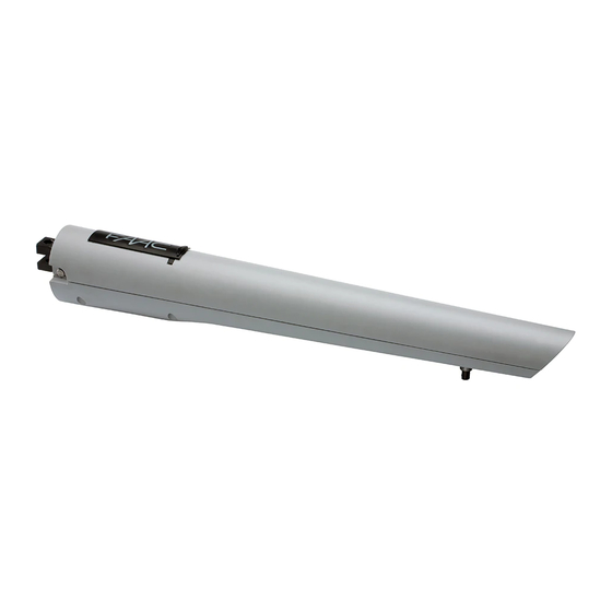
S418
Swing Gate Operator
FAAC International Inc.
West Coast Operations
357 South Acacia Avenue
Unit 357
Fullerton, CA 92831
Tel. 800 221 8278
Advertisement
Table of Contents

Related Manuals for FAAC S418


Summary of Contents for FAAC S418
- Page 1 S418 Swing Gate Operator UL325 - UL991 FAAC International Inc. FAAC International Inc. Headquarter & East Coast Operations West Coast Operations 5151 Sunbeam Road 357 South Acacia Avenue Suites 9-11 Unit 357 Jacksonville, FL 32257 Fullerton, CA 92831 Tel. 866 925 3222 Tel.
-
Page 2: Table Of Contents
= Information regarding personal safety and proper maintanence of the product. FAAC Model S418 - Rev: 01.0C.05 - APR 2011 FA A C Mo d el S 418 S w in g G at e O p e ra t o r... -
Page 3: Important Safety Information
• Use only FAAC “Photobeam” photoelectric eyes to comply with UL325. FA A C Mo de l S4 18 S w i n g G at e Ope r ator... -
Page 4: General Safety Precautions
• Install devices such as reversing edges and photo • Use only FAAC MSE MO, CN60 or M60 edge beams to provide better protection for personal sensors. property and pedestrians. Install reversing devices that are appropriate to the gate design and application. -
Page 5: Ul325 Gate Operator Classifications
Installing the Warning Signs This FAAC swing gate operator is supplied with two warning signs to alert people that a possible hazard exists and that appropriate actions should be taken to avoid the hazard or to reduce exposure to it. -
Page 6: Description
FA A C M o d el S 41 8 S win g Ga t e Op e r a t o r DESCRIPTION The FAAC Model S418 automated system for swing-leaf gates is an electro-mechanical operator which transmits its movement to the gate leaf by means of a worm-screw system. -
Page 7: Technical Specifications
TECHNICAL SPECIFICATIONS laying electrical cables, use conduits with When adequate rigidity and/or flexibility. Technical Specifications S418 To avoid any type of interference, we advise you to always separate low-voltage accessories and Power Supply (VDC) command connection wiring from power supply cables, Nominal Power (W) use separate sheaths. -
Page 8: Installation Dimensions
INSTALLATION DIMENSIONS Determine the assembly position of the operator, referring to Figure 4 and related table. It is a good idea at this stage to choose whether or not you want to use the built in mechanical positive stops; eliminating the mechanical stops increases the working stroke of the operator and values A and B must be changed. -
Page 9: Installing The Operator
3.3.1 General Rules for Determining Installation Values If the size of the pillar or the position of the hinge does not • To obtain opening of the leaf to 90°: A+B=C. permit installation of the operator, a niche will have to be made in the pillar (as indicated in Figure 6) in order not to •... - Page 10 4. Check that the front fitting is in the position 2. Secure the rear bracket, as indicated in indicated in Figure 12 (with the mechanical stop Figure 10, so as to follow the A and B values at closing) or in Figure 13 (with no mechanical determined previously.
- Page 11 6. Secure the operator to the rear bracket using 10. Prepare the operator for manual operation, the appropriate bolt supplied, as indicated in see Section 5, and move the leaf manually, Figure 15. checking that it completes the entire opening operation required, stopping at the mechanical stops.
-
Page 12: Wiring The Operator
2. Manually move the leaf into its closing position. MECHANICAL STOPS 3. Loosen the securing screw, Figure 21 Ref. 1. The The S418 operator is supplied with mechanical stops screw does not need to be completely removed. on opening and closing as standard. These may be used in place of mechanical stop-points for the leaf. -
Page 13: Automated System Test
RESTORING NORMAL OPERATION AUTOMATED SYSTEM TEST To restore normal operation mode, proceed as follows: • Once all necessary electrical connections have 1. Ensure that the system is not powered. been made, power up the system and program the control unit based on your individual needs 2. -
Page 14: Special Applications
REPAIRS The user must not carry out any repairs or maintenance operations; these must be performed only and exclusively by qualified FAAC personnel or FAAC ser- vice centers. ACCESSORIES For a list of available accessories, see the FAAC catalogue. -
Page 15: S418 Parts Diagram
S418 PARTS DIAGRAM Part Part Description Part Part Description Number Number 713002 402 RELEASE KEY 60202355 411 BUSH FOR FIXING WORM GEAR 63001555 RELEASE COVER S418 63001545 SET OF 10 SCREWS Ø4.8X13 63001565 RELEASE S418 S418 63001575 SHELL S418 63001535... -
Page 16: Limited Warranty
FAAC S.p.A. intended provided it has been properly installed or FAAC International, Inc. The warranty herein and operated.
Need help?
Do you have a question about the S418 and is the answer not in the manual?
Questions and answers