Table of Contents
Advertisement
Advertisement
Table of Contents

Related Manuals for FAAC S800H ENC


Summary of Contents for FAAC S800H ENC
- Page 1 S800H ENC 24V Underground Hydraulic Swing Gate Operator UL325 - UL991 FAAC International Inc. FAAC International Inc. Headquarter & East Coast Operations West Coast Operations 3160 Murrell Road 357 South Acacia Avenue Rockledge, FL 32955 Fullerton, CA 92831 Tel. 800 221 8278...
-
Page 2: Table Of Contents
TABLE OF CONTENTS IMPORTANT SAFETY INFORMATION Important Safety Instructions Important Installation Instructions General Safety Precautions UL325 Gate Operator Classifications Installing the Warning Signs DESCRIPTION AND TECHNICAL SPECIFICATIONS Technical Specifications Electrical Layout INSTALLATION OF THE SUPPORT BOX INSTALLATION THE OPERATOR Internal Mechanical Positive Stops Adjustment Of The Travel-Limit Stops Final Steps MANUAL OPERATIONS... -
Page 3: Important Safety Information
• Locate one or more non-contact sensors where the risk of entrapment or obstruction exists, such as at the reachable perimeter of a moving gate or barrier. • Use only FAAC “Photobeam” photoelectric eyes to comply with UL325. -
Page 4: General Safety Precautions
Install devices such as reversing edges and photo beams to provide better protection for personal • Use only FAAC MSE MO, CN60 or M60 edge sensors. property and pedestrians. Install reversing devices that are appropriate to the gate design and application. -
Page 5: Ul325 Gate Operator Classifications
Installing the Warning Signs This FAAC swing gate operator is supplied with two warning signs to alert people that a possible hazard exists and that appropriate actions should be taken to avoid the hazard or to reduce exposure to it. -
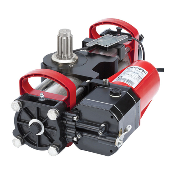
Page 6: Description And Technical Specifications
The opera- tor iinclude the hydraulic control unit (pump) and the hydraulic The S800H ENC operator is designed and built to automate drive unit in the same body. The model with a hydraulic lock swing leaf gates. -
Page 7: Installation Of The Support Box
2 INSTALLATION OF THE SUPPORT BOX 13/16 Dimensions in inches 27/32 2” Drain ” TO ENSURE A CORRECT INSTALLATION, THE LEAF ROTATION AXIS MUST BE PERFECTLY ALIGNED WITH THE OPERATOR... -
Page 8: Installation The Operator
3 INSTALLATION OF THE OPERATOR 1) Move the gate to its open position. 5) Turn the pinion of the operator using the supplied plastic wrench, in the closing direction, until it reaches the internal stop 2) Hydraulically release the operator, using the release handle of the piston and remove the wrench. - Page 9 7) Turn the operator pinion with the supplied wrench until it points to the open position (90° from close) and then remove the wrench (see Fig. 7) Fig.9 10) Place the supplied plastic wrench with the spacer under the operator, as shown in figure 10 ref. B, C 12) Insert and tighten the fastening long bolts with the supplied lockwasher as shown in Fig.
-
Page 10: Internal Mechanical Positive Stops
3.1 INTERNAL MECHANICAL POSITIVE STOPS The S800H ENC operator is supplied with internal opening and closing mechanical stops that facilitate the installation because there is no need to build external mechanical stops. The mechanical travel-limit stops (POSITIVE STOPS) can be adjusted in the last 30°... -
Page 11: Manual Operations
4 MANUAL OPERATION 4.1 BUILT IN HYDRAULIC RELEASE 4.2.1 INSTALLATION PROCEDURE If the gate must be moved manually due to a power failure or 1. Manually release the operator and make sure it is turned off operator’s malfunction you can use the built in hydraulic release with the batteries disconnected device with the release handle (Fig.17): 2. -
Page 12: Maintenance
4.2.3 USING THE RELEASE SYSTEM 3) Let air come out from the hydraulic circuit through the bleed screw until non-emulsified oil comes out. To release the operator, remove the plastic cover, insert the key 4) Tighten the bleed screw before the operator ends the opening and turn the release lock counter-clockwise for about one turn. -
Page 13: Encoder Connection
6 ENCODER CONNECTION To verify the proper assignement of LEAF 1 - ENCODER 1 The S800H operator comes with an encoder system that allows - MOTOR 1 and LEAF 2 - ENCODER 2 - MOTOR 2, use the the control board to monitor the postion of the leaf connected LEDs visible through the encoder control board shell, as to the operator at any time. - Page 14 6 SPARE PARTS Part Part Number Description Part Part Number Description 63000276 Tank Gasket 701103 Screw M4x12 mm SS 7090010015 O-Ring 4.48x1.78 mm 7090190015 O-Ring 14x1.78 mm 7090030015 O-Ring 6.75x1.78 mm 63002635 Motor Cover 703101 Lock Washer 63000376 Motor and Flange 701632 Screw M4x25 mm 701072...
- Page 15 63000196 O-Ring 50.47x2.62 mm 490112 Load Bearing Box Steel 70992025 Gasket 714019 Qt.1 FAAC Oil: 1 qt. 7090635 O-Ring 5x1.5 mm 7140251 Qt.1 FAAC Arctic Oil: 1 qt. 7090490025 O-Ring 64.77x2.62 mm 2182.1 Seal Kit 63002465 Foundation Plate 63000106 Piston...
-
Page 16: S800H Parts Diagrams
1. E024U CONTROL BOARD DESCRIPTION & CHARACTERISTICS SETTING DL14 DL15 DL16 DL17 DL18 DL19 DL20 DL21 DL22 Fig. A1 1.1 TECHNICAL SPECIFICATIONS 1.2 LAYOUT AND COMPONENTS Main power supply RADIO 115 V~ 60 Hz Connector for the radio receiver Secondary power BATTERY 24 Vdc - 16 A max. - Page 17 2. INPUT / OUTPUT DESCRIPTION Encoder 24 VDC Maglock B STP CL OP OPEN Fig. A2 LABEL FUNCTION 2 EASY 2 EASY 2easy BUS input for encoders (S800H and S450H only), XIB and loop detector boards OPEN A N.O. Contact for total opening command OPEN B: N.O.
- Page 18 3. SAFETY DEVICE CONNECTIONS Entrapment protection To comply with the UL325 standard for gate operators every Connection of One Pair of Monitored Closing Photocells entrapment zone, as defined in ASTMF2200, must be pro- tected by two independent entrapment protection devices. One of the devices is inherent in the E024U control boards design, the other can be external, like a photocell or an edge sensor.
- Page 19 Only one monitored photocell can be connected to the Connection of One Pair of Closing Photocells Closing or Opening safety inputs. More than one photocell (monitored), One Pair of Opening Photocells or other device can be connected to the safety inputs, but (monitored) and One pair of Opening/Closing they will not be monitored.
-
Page 20: Operating Logic
4. PROGRAMMING 4.1 DIP SWITCH DS1 SETTINGS FOR OPERATING LOGIC OPERATING LOGIC DS 1: SW 1 - SW 2 - SW 3 PAUSE LOGIC SW 1 SW 2 SW 3 DESCRIPTION TIME E (default) One command opens, the next one closes. A command during opening stops the gate Semiautomatic 0 - 4... - Page 21 4.2 ADJUSTING TRIMMERS – FORCE ADJUSTMENT MOTOR 1 Turn clockwise to increase the opening and closing force TR 2 – FORCE ADJUSTEMENT MOTOR 2 Turn clockwise to increase the opening and closing force TR 3 – SPEED ADJUSTMENT FOR MOTOR1 AND MOTOR 2 Turn clockwise to increase the opening and closing speed TR 4 –...
- Page 22 4.3 DIP SWITCH DS1 SETTINGS FOR BOARD SETUP BOARD SETUP DS 1: SW 4 to SW 12 The opening of leaf 2 is delayed after the opening of leaf 1. This is to OPENING DELAY SW 4 avoid that the gate’s leafs interfere with each other during the initial part 0 sec (default) of the movement.
- Page 23 4.4 DIP SWITCH DS2 SETTINGS FOR OPERATOR TYPE AND LOCK MODE SETTING DL 1 DL 2 DL 3 DL 4 DL 5 IMPORTANT DS 2 DS 2 OPERATOR SELECTION LOCK OUTPUT MODE OPERATOR TYPE SW 1 SW 2 SW 3 OUTPUT MODE SW 4 S450H, S800H...
- Page 24 LED STATUS In BOLD the normal state with gate closed and working DESCRIPTION ON STEADY BLINKING Board working on AC Board working on LED BATTERY power battery power or ext Battery charging supply LED +24 Main power OFF Main power present SLOW BLINK (1 sec.
- Page 25 The diagnostic LED shows only one error condition at a time, with the priority of the below table. In case there is more than one error once one is eliminated the LED will show the next LED ERROR DISPLAY NUMBER OF ERROR CONDITION SOLUTION FLASHES...
- Page 26 At the point where you want the slowdown to start give an This is a more detailed description of what happens after an OPEN A command with the push button or the remote that obstacle detection: is already stored in memory. Leaf 2 starts to slow down and stops when it reaches the mechanical stop or FCA2.
- Page 27 On the back panel there are: the control board, the power supply AC POWER CONNECTION and additional accessories. To connect AC power to the controller: 1. Turn the circuit breaker for the AC gate operator power OFF Power outlet before connecting the AC input wires. AC connection and switch 2.
- Page 28 For the upgrade you need a USB Flash Drive, where you have BLACK 12VDC, 8 amp Battery to copy the file supplied by FAAC. Then follow these steps: JUMPER Disconnect the batteries if they are present. 12VDC, 8 amp Turn the AC power off and insert the Flash Drive into the...
- Page 29 11. FUNCTION LOGICS LOGIC “E” PULSES SYSTEM STATUS OPEN A OPEN B STOP FSW OP FSW CL FSW CL/OP no effect no effect no effect CLOSED opens the leaves opens leaf 1 no effect (OPEN disabled) (OPEN disabled) (OPEN disabled) stops and opens at release immediately stops operation...
- Page 30 LOGIC “EP” PULSES SYSTEM STATUS OPEN A OPEN B STOP FSW OP FSW CL FSW CL/OP no effect no effect no effect CLOSED opens the leaves opens leaf 1 no effect (OPEN disabled) (OPEN disabled) (OPEN disabled) stops and opens at release immediately OPENING stops operation (1) stops operation...
- Page 31 LOGIC “B” PULSES SYSTEM STATUS OPEN A OPEN B STOP FSW OP FSW CL FSW CL/OP no effect no effect no effect CLOSED opens the leaves no effect no effect (OPEN disabled) (OPEN disabled) (OPEN disabled) stops and, at release, closes OPENING no effect closes leaves...
- Page 32 FAAC S.p.A. or FAAC International, Inc. The warranty herein FAAC International, Inc.’s obligations under above set forth shall not be deemed to cover...
Need help?
Do you have a question about the S800H ENC and is the answer not in the manual?
Questions and answers