FAAC 400 Series Instruction Manual
Hide thumbs
Also See for 400 Series:
- Instruction manual (32 pages) ,
- User manual (30 pages) ,
- Installation manual (24 pages)
Table of Contents
Advertisement
Advertisement
Table of Contents

Related Manuals for FAAC 400 Series


Summary of Contents for FAAC 400 Series
- Page 1 Translation of the original instructions...
- Page 2 Nessuna parte di questo manuale può essere riprodotta, archiviata, distribuita a terzi né altrimenti copiata, in qualsiasi formato e con qualsiasi mezzo, sia esso elettronico, meccanico o tramite fotocopia, senza il preventivo consenso scritto di FAAC S.p.A. Tutti i nomi e i marchi citati sono di proprietà dei rispettivi fabbricanti.
-
Page 3: Table Of Contents
CONTENTS TABLES 1 Technical data ........... . . 7 1. -
Page 4: Introduction To The Instruction Manual
When drafting the manual, the results of the risk assessment con- NOTES AND WARNINGS IN THE INSTRUCTIONS ducted by FAAC S.p.A. on the entire product life cycle have been taken WARNING ELECTRIC SHOCK HAZARD - The operation or stage described into account in order to implement effective risk reduction measures. - Page 5 PERSONAL PROTECTIVE EQUIPMENT TOOLS (type and size) Personal protective equipment must be worn to protect against hazards (e.g. crushing, cutting, shearing etc.): Hex wrench of the size indicated in figures (6, 8...) 2, 3, 5 Obligation to wear safety footwear. Hex key of the size indicated in figures (6, 8...) Obligation to wear mask/goggles to protect the eyes from the risk of 13, 14, 17...
-
Page 6: Safety Recommendations
2. SAFETY RECOMMENDATIONS 2.2 TRANSPORT AND STORAGE This product is placed onto the market as “partly completed machin- ery”, therefore it cannot be commissioned until the machine in which PALLETISED SUPPLY it has been incorporated has been identified and declared to conform RISKS to the Machinery Directive 2006/42/EC by the actual Manufacturer. -
Page 7: Unpacking And Handling
2.3 UNPACKING AND HANDLING RISKS PERSONAL PROTECTIVE EQUIPMENT 1. Open the package and remove the contents. 2. Check that all components are present and intact. 3. Dispose of the packaging materials. The packaging materials (plastic, polystyrene etc.) must not be left within reach of children as they are potential sources of danger. -
Page 8: Intended Use
- It is prohibited to use the automation system in the presence of faults which could compromise safety. The FAAC series 400 actuators have been designed for use on hori- - It is prohibited to use the automation system with the fixed and/ zontal movement swing gates intended for installation in areas that or mobile guards removed or altered. -
Page 9: Technical Characteristics
OIL TYPE 400 (FAAC HP OIL), 400 Winter (FAAC HP2 OIL) the Winter versions oil. are suitable for installation in environments with temperatures as TYPE OF HYDRAULIC LOCK the hydraulic lock makes it impossible to low as -40°C. - Page 10 70 cycles/hour 60 cycles/hour 50 cycles/hour 50 cycles/hour Protection rating IP55 IP55 IP55 IP55 Oil type FAAC HP OIL FAAC HP OIL FAAC HP OIL FAAC HP OIL [WINTER version] [FAAC HP2 OIL] Weight 8.9 kg 8.9 kg 10.5 kg 10.5 kg...
-
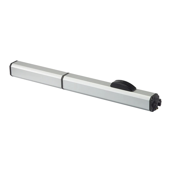
Page 11: Component Identification
3.7 COMPONENT IDENTIFICATION COMPONENTS SUPPLIED Actuator body Joint Casing cover with plugs Casing fastening tie-rods with washers Casing Front bracket with fixing pin and nut Rear fork with fixing pins and nuts Rear bracket arm Rear bracket plate Breather screw Oil filler plug Power cable Lock cover... -
Page 12: Manual Operation
3.9 MANUAL OPERATION Releasing the actuator The actuator has to be released in order to operate the leaf manually. Disconnect the power supply from the automation before releasing the actuator. During manual operation, gently guide the leaf the whole way. Do not push it and let it slide freely. -
Page 13: Installation Requirements
4. INSTALLATION REQUIREMENTS 4.1 MECHANICAL REQUIREMENTS 4.2 ELECTRICAL SYSTEM The mechanical structural components must comply with the require- Always shut off the power supply before performing any work. If the ments of EN 12604. Before installing the automation, the suitability disconnect switch is not in view, apply a warning sign stating “WARNING - Maintenance in Progress”. -
Page 14: Example System
4.3 EXAMPLE SYSTEM The example is purely an illustration and is only one of the possible applications of the 400. 1 Mains power supply 3G 1.5 sq. mm Junction box 2 Board enclosure and circuit breakers and differential switch Key button 3 400 actuators 4G 1.5 sq. -
Page 15: Determining The Position Of The Rear Bracket
5.1 DETERMINING THE POSITION OF THE REAR BRACKET The actuator must be installed inside the property, with the gate opening inwards. For applications in which the gate opens outwards, see appendix. Refer to the following tables to establish the correct position for the rear bracket and then install it: - A and B rear bracket installation measurements - D distance between the edge of the pillar and the axis of the hinge... -
Page 16: Measurements 400 L
3 Measurements 400 L (1) a closing electric lock has to be installed (2) the speed of the leaf could be uneven during the final stage of movement (1-2) (1-2) (1-2) (1-2) (1-2) (1-2) (1-2) (1-2) (1-2) (1-2) (1-2) 100 105° 110°... -
Page 17: Installing The Rear Bracket
5.2 INSTALLING THE REAR BRACKET The structure of the pillar must be suitable for fixing the actuator. If neces- sary, create a solid support base to attach it to. It is the responsibility of the installer to provide suitable fastenings for the applied loads. Welding must be carried out in a workmanlike manner. -
Page 18: Installing The Fork And Joint
5.3 INSTALLING THE FORK AND JOINT INSTALLING THE REAR FORK If you use the SAFEcoder accessory, install the rear fork following the instruc- tions provided in the specific manual. 1. Grease the long pin. 2. Fasten the rear fork to the actuator using the long pin ( 1 6). -
Page 19: Installing The Casing
■ FASTENING BY WELDING ( 22-A) Welding must be carried out in a workmanlike manner. Safety may be affected if it is carried out badly. Connect the earth (-) of the welder to the leaf, NOT to the actuator. Protect the rod from weld spatter. ■... -
Page 20: Start Up
6. START UP RISKS PERSONAL PROTECTIVE EQUIPMENT Before making electrical connections, cut off the automation power sup- ply. If the disconnect switch is not in view, apply a warning sign stating “WARNING - Maintenance in Progress”. 1. Remove the breather screw ( 2 6). -
Page 21: Putting Into Service
7. PUTTING INTO SERVICE 8. ACCESSORIES 7.1 FINAL CHECKS Refer to the specific instructions provided. 1. Make sure that the forces generated by the leaf are within the limits permitted by the current regulations. Use an impact force tester in accordance with standard EN 12453 . For non-EU Plate to embed in masonry Fitting for RTA sheath countries, of there are no specific local regulations, the force must... -
Page 22: Maintenance
Make sure that the pictograms are present and intact. If they Do not modify the original components in any way. are missing or damaged, replace them. FAAC S.p.A. disclaims any liability for damage caused by components that are Operations Frequency in months modified or tampered with. -
Page 23: Operational Problems
9.2 OPERATIONAL PROBLEMS 6 Troubleshooting CONDITION FINDING SOLUTIONS Check that the actuator is not released. Check that there is power. Check the motor connection. Check the adjustment of the by-pass screws. No movement Check the connection and operation of the thrust capacitor. -
Page 24: Emergency Use
10.2 EMERGENCY USE Releasing the actuator Environmental phenomena, even occasional, such as ice, snow and strong wind may hinder correct operation of the automation and affect component integrity and may become a potential source of danger. In emergencies or if there is a fault, turn off the power supply to the automation . -
Page 25: Limitations Of Use 400 Cbc, 400 Cbac, 400 Sb
1 Limitations of use in relation to wind The tables indicate the maximum permitted wind force (Beaufort scale) for the 400 with maximum force regulation (by-pass) in relation to the: - surface of the leaf exposed to the wind - length of the leaf - actuator model Winds stronger than those permitted could affect the operation of the 400. -
Page 26: Limitations Of Use 400 Sbs
9 Limitations of use 400 SBS Leaf length (m) Exposed surface (m²) 10 Limitations of use 400 SBS L Leaf length (m) Exposed surface (m²) 732871 - Rev. D... -
Page 27: 1 Outward Opening - Measurements 400
2 Outward opening applications Refer to the following tables to establish the correct rear bracket - during start-up and when not powered, invert the phase wires of position. The maximum opening angle of the leaf is indicated in the motor to change the direction of travel. the tables. -
Page 28: 2 Outward Opening - Measurements 400 L
12 Outward opening - Measurements 400 L (1) a closing electric lock has to be installed (2) the speed of the leaf could be uneven during the final stage of movement (1-2) (1-2) (1-2) (1-2) (1-2) (1-2) (1-2) (1-2) (1-2) (1-2) 100 110°... - Page 29 732871 - Rev. D...
- Page 32 FAAC S.p.A. Soc. Unipersonale Via Calari, 10 - 40069 Zola Predosa BOLOGNA - ITALY Tel. +39 051 61724 - Fax +39 051 09 57 820 www.faac.it - www.faactechnologies.com 732871 - Rev. D...
Need help?
Do you have a question about the 400 Series and is the answer not in the manual?
Questions and answers