FAAC S418 Manual
Swing gate operator
Hide thumbs
Also See for S418:
- Manual (36 pages) ,
- User manual (30 pages) ,
- Instruction manual (16 pages)
Table of Contents
Advertisement
Quick Links
Advertisement
Table of Contents

Related Manuals for FAAC S418


Summary of Contents for FAAC S418
- Page 1 S418 Swing Gate Operator UL325 - UL991 FAAC International Inc. FAAC International Inc. Headquarter & East Coast Operations West Coast Operations 3160 Murrell Rd 357 South Acacia Avenue Rockledge, FL 32955 Unit 357 Tel. 800 221 8278 Fullerton, CA 92831...
-
Page 2: Table Of Contents
= Information regarding personal safety and proper maintanence of the product. FAAC Model S418 - Rev: 03 - OCT 2014 FA A C Mo d el S 418 S w in g G at e O p e ra t o r... -
Page 3: Important Safety Information
• Use only FAAC “Photobeam” photoelectric eyes to comply with UL325. FA A C Mo de l S4 18 S w i n g G at e Ope r ator... -
Page 4: General Safety Precautions
• Install devices such as reversing edges and photo • Use only FAAC MSE MO, CN60 or M60 edge beams to provide better protection for personal sensors. property and pedestrians. Install reversing devices that are appropriate to the gate design and application. -
Page 5: Ul325 Gate Operator Classifications
Installing the Warning Signs This FAAC swing gate operator is supplied with two warning signs to alert people that a possible hazard exists and that appropriate actions should be taken to avoid the hazard or to reduce exposure to it. -
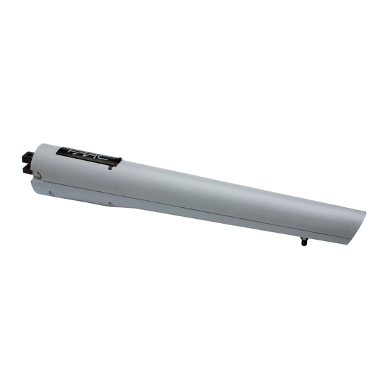
Page 6: Description
M o d e l S 41 8 S win g Ga t e Op e r a t o r DESCRIPTION The FAAC Model S418 automated system for swing-leaf gates is an electro-mechanical operator which transmits its movement to the gate leaf by means of a worm-screw system. -
Page 7: Technical Specifications
The structure of the gate directly influences the reliability and safety of the automated system. To ensure correct Technical Specifications S418 operation, the structure of the existing gate, or that to be Power Supply (VDC) fitted, must have the following characteristics: Nominal Power (W) •... -
Page 8: Installing The Operator
3.3.1 General Rules for Determining Installation Values If the size of the pillar or the position of the hinge does not permit the proper installation of the operator, a niche • To obtain opening of the leaf to 90°: A+B=C. will have to be made in the pillar (as indicated in Figure 6) •... - Page 9 Secure the rear bracket, as indicated in Figure 10, so as to follow the A and B values determined previously. 2⅛ Dimensions in Inches Fig. 12 Fig. 10 3. Secure the rear fitting of the operator as indicated in Figure 11. 1⅜...
-
Page 10: Wiring The Operator
MECHANICAL STOPS Fig. 16 The S418 operator is supplied with mechanical stops on opening and closing as standard. These may be used in place of mechanical stop-points for the leaf. For adjustment of the stops, proceed as follows: 3.6.1 Mechanical Stop at Opening... -
Page 11: Automated System Test
The mechanical stop is coupled to a toothed sector, Figure 21 Ref. 2. In the case of obstructions during movement, check that the coupling is free. DO NOT FORCE IT. Fig. 19 Tighten the securing screw once again. Fig. 22 AUTOMATED SYSTEM TEST Fig. -
Page 12: Restoring Normal Operation
Manually move the leaf until the device engages and operations; these must be performed only and exclusively the leaf locks. by qualified FAAC personnel or FAAC service centers. Power up the system and perform several open/close operations to check that all functions of the automated system have been restored. -
Page 13: S418 Parts Diagram
S418 PARTS DIAGRAM Part Part Description Part Part Description Number Number 713002 RELEASE KEY 63001545 10 SCREWS Ø4.8X13 S418 63001555 RELEASE COVER 63001535 FRONT CAP 63001565 RELEASE ASSEMBLY NOTA05 GLAND 63001575 OPERATOR BODY 701459 AUT. 3.5X 13 6954 63001585 REAR ADJUSTABLE BRACKET 701405 SCREW AUT. - Page 14 E024U CONTROL BOARD DESCRIPTION & CHARACTERISTICS SETTING DL14 DL15 DL16 DL17 DL18 DL19 DL20 DL21 DL22 Fig. A1 1.1 TECHNICAL SPECIFICATIONS 1.2 LAYOUT AND COMPONENTS Main power supply RADIO 115 V~ 60 Hz Connector for the radio receiver Secondary power BATTERY 24 Vdc - 16 A max.
- Page 15 2. INPUT / OUTPUT DESCRIPTION Encoder 24 VDC Maglock B STP CL OP OPEN Fig. A2 LABEL FUNCTION 2 EASY 2 EASY 2easy BUS input for encoders (S800H and S450H only), XIB and loop detector boards OPEN A N.O. Contact for total opening command OPEN B / OPEN B: N.O.
- Page 16 PHOTOCELLS CONNECTIONS How to connect Normally Open contacts. How to connect Normally Close contacts. (Connect them in parallel) (Connect them in series) Fig. A3 Fig. A4 The E024U board allows the connection of several safety devices (for example photocells). With photocells you can activate the FAILSAFE function, which, before each movement of the ope- rator, tests each fotocells.
- Page 17 Connection of two pairs of closing photocells RX= Photocell Receiver TX= Ptotocell Transmitter STP CL OP CL= Closing OP= Opening Other optional safety devices to connect in series To use the FAIL-SAFE mode connect the nega- tive power supply of the transmitters to OUT (pin 9), and set dip-switch 11 and 12 to ON on DS1...
- Page 18 Connection of a pair of closing photocells and a pair of opening photocells STP CL OP RX= Photocell Receiver TX= Ptotocell Transmitter CL= Closing OP= Opening To use the FAIL-SAFE mode connect the negative power supply of the transmitters to OUT (pin 9), and set dip- switch 11 and 12 to ON on DS1 Fig.
-
Page 19: Operating Logic
PROGRAMMING 4.1 DIP SWITCH DS1 SETTINGS FOR OPERATING LOGIC OPERATING LOGIC DS 1: SW 1 - SW 2 - SW 3 PAUSE LOGIC DESCRIPTION TIME E (default) One command opens, the next one closes. A command du- OFF OFF OFF ring opening stops the gate Semiautomatic 0 - 4... - Page 20 4.2 ADJUSTING TRIMMERS – FORCE ADJUSTMENT MOTOR 1 Turn clockwise to increase the opening and closing force TR 2 – FORCE ADJUSTEMENT MOTOR 2 Turn clockwise to increase the opening and closing force TR 3 – SPEED ADJUSTMENT FOR MOTOR1 AND MOTOR 2 Turn clockwise to increase the opening and closing speed TR 4 –...
- Page 21 4.3 DIP SWITCH DS1 SETTINGS FOR BOARD SETUP BOARD SETUP DS 1: SW 4 to SW 12 The opening of leaf 2 is delayed after the opening of leaf 1. This is to avoid SW 4 OPENING DELAY that the gate’s leafs interfere with each other during the initial part of the 0 sec (default) movement.
- Page 22 OUTPUT MODE SW 4 S450H, S800H OFF OFF OFF Active only for 3 sec. after an open impulse (from gate closed) S418 OFF OFF Active always except 3 sec. before an opening 415, 390, 770 OFF OFF LED DIAGNOSTICS SETTING...
- Page 23 LED STATUS In BOLD the normal state with gate closed and working DESCRIPTION ON STEADY BLINKING Board working on AC Board working on LED BATTERY power battery power or ext Battery charging supply LED +24 Main power present Main power OFF SLOW BLINK (1 sec.
- Page 24 The diagnostic LED shows only one error condition at a time, with the priority of the below table. In case there is more than one error once one is eliminated the LED will show the next LED ERROR DISPLAY NUMBER OF ERROR CONDITION SOLUTION FLASHES...
- Page 25 At the point where you want the slowdown to start give an ENCLOSURE OPEN A command with the push button or the remote that is already stored in memory. Leaf 2 starts to slow down and The E024U board is supplied on a panel that fits in a 16x14” stops when it reaches the mechanical stop or FCA2.
- Page 26 POWER CONNECTION 8.1 POWER SUPPLY AC POWER GUIDELINES: The E024U board is powered by a high efficiency switching power supply that takes 115VAC input and provides 36VDC to THE E024U control board and power supply uses a single power the board. On the power supply board there is only one phase AC power line to operate, charge the batteries, and power repleaceble fuse: 6.3A timed gate accessories.
- Page 27 DL 1 DL 2 DL 3 DL 4 DL 5 For the upgrade you need a USB Flash Drive, where you have to copy the file supplied by FAAC. Then follow these steps: SETTING Disconnect the batteries if they are present.
- Page 28 11. FUNCTION LOGICS LOGIC “E” PULSES SYSTEM STATUS OPEN A OPEN B STOP FSW OP FSW CL FSW CL/OP no effect no effect no effect CLOSED opens the leaves opens leaf 1 no effect (OPEN disabled) (OPEN disabled) (OPEN disabled) stops and opens at release immediately stops operation...
- Page 29 LOGIC “EP” PULSES SYSTEM STATUS OPEN A OPEN B STOP FSW OP FSW CL FSW CL/OP no effect no effect no effect CLOSED opens the leaves opens leaf 1 no effect (OPEN disabled) (OPEN disabled) (OPEN disabled) stops and opens at release immediately OPENING stops operation (1) stops operation...
- Page 30 LOGIC “B” PULSES SYSTEM STATUS OPEN A OPEN B STOP FSW OP FSW CL FSW CL/OP no effect no effect no effect CLOSED opens the leaves no effect no effect (OPEN disabled) (OPEN disabled) (OPEN disabled) stops and, at release, closes OPENING no effect closes leaves...
-
Page 31: Limited Warranty
FAAC S.p.A. intended provided it has been properly installed or FAAC International, Inc. The warranty herein and operated.
Need help?
Do you have a question about the S418 and is the answer not in the manual?
Questions and answers