Table of Contents
Advertisement
Advertisement
Table of Contents

Related Manuals for Matrix VS-S74


Summary of Contents for Matrix VS-S74
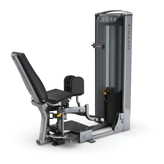
- Page 1 OWNERS MANUAL Versa Single-Station Strength VS-S74 Hip Adduction/Abduction...
-
Page 2: Table Of Contents
Table Of Contents Safety, General Care & Maintenence ..........3 Getting Started (Product Specifications) ........5 Assembly Information ................ 6 Markings ....................7 Parts List ....................8 Installation & Assembly: Value Line Part 1 User Frame Assembly ............10 Part 2 Weight Stack Assembly ........... 11 Part 3 Weight Stack To User Frame Assembly ...... -
Page 3: Safety, General Care & Maintenence
IMPORTANT SAFETY INSTRUCTIONS IMPORTANT SAFETY INFORMATION It is the sole responsibility of the purchaser of Matrix products to instruct all individuals, whether they are the end user or su- pervising personnel on proper usage of the equipment. It is recommended that all users of Matrix exercise equipment be informed of the following information prior to its use. - Page 4 IMPORTANT SAFETY INSTRUCTIONS WARNING: This product contains chemicals known to the State of California to cause cancer and birth defects or other reproductive harm. WARNING: SERIOUS INJURY CAN OCCUR ON THIS EQUIPMENT. FOLLOW THESE PRECAUTIONS TO AVOID INJURY! Never allow children on strength training equipment. Teenagers must be supervised at all times while using this equipment.
-
Page 5: Getting Started (Product Specifications)
GETTING STARTED EXERCISE PLACARD | PRODUCT SPECIFICATIONS | MAINTENANCE CHECKLIST EXERCISE PLACARD PRODUCT SPECIFICATIONS TECH SPECS Overall dimensions 64”L X 67”W X 66”H Light Stack = 516 lbs (235 kg), Heavy Stack = 586 lbs (266 Weight Shipping weight 356 lbs (162 kg) WARRANTY (Valid in USA only) Frame (not coatings) 10 years... -
Page 6: Assembly Information
UNPACKING Thank you for purchasing a Matrix product. This machine is an EN957-1 and EN957-2 compliant Class S product. Your Ma- trix product is inspected before it is packaged. It is shipped in multiple pieces to facilitate the compact packaging of the machine. -
Page 7: Markings
MARKINGS WARNING LABEL LOCATIONS... -
Page 8: Parts List
Parts List DESCRIPTION Outer Frame Support M10 Nylock Nut User Frame M10 Flat Washer Wide Cupped Flange M10 X 125L Socket Head Cap Screw Weight Stack Frame M10 X 20L Socket Head Cap Screw Cable M8 Nylock Nut M10 Washer (Ø20 mm) Axle Right Arm Assembly Spacer (Ø26.5 mm) - Page 9 Parts List DESCRIPTION Left Arm Assembly M10 X 30L Socket Head Cap Screw Handlebar Assembly Back Pad M10 X 75L Socket Head Cap Screw M10 X 15L Button Head Cap Screw Rubber Bumper Thigh Pad Front Shroud Rear Shroud M8 X 25L SHC Large M8 Flat Washer (Ø20 mm) Top Cap Top Cap Cover...
-
Page 10: Part 1 User Frame Assembly
ASSEMBLY PART 1: USER FRAME ASSEMBLY STEP 1 | USER FRAME INSTRUCTIONS & NOTES DESCRIPTION QUANTITY Outer Frame Support M10 Nylock Nut User Frame M10 Flat Washer Wide Cupped Flange M10 X 125L SHC Install the user frame hardware as shown, but DO NOT FULLY TIGHTEN . -
Page 11: Part 2 Weight Stack Assembly
ASSEMBLY PART 2: STACK ASSEMBLY STEP 1 | WEIGHT STACK ASSEMBLY INSTRUCTIONS & NOTES DESCRIPTION QUANTITY Weight Stack Frame Disassemble the stack frame hardware as shown - set aside for reassembly... -
Page 12: Part 3 Weight Stack To User Frame Assembly
ASSEMBLY PART 3: STACK & USER FRAME ASSEMBLY STEP 1 | USER FRAME TO WEIGHT STACK ASSEMBLY INSTRUCTIONS & NOTES Assemble the weight stack to the user frame as shown. - Page 13 ASSEMBLY PART 3: STACK & USER FRAME ASSEMBLY STEP 2 | CAM ASSEMBLY INSTRUCTIONS & NOTES DESCRIPTION QUANTITY M10 Flat Washer M10 X 20L SHC Install the hardware as shown, but DO NOT FULLY TIGHTEN .
- Page 14 ASSEMBLY PART 3: STACK & USER FRAME ASSEMBLY STEP 3 | ADJUSTABLE PULLEY ASSEMBLY INSTRUCTION & NOTES DESCRIPTION QUANTITY Cable Route cable through frame tube and reassemble pulley. Replace the hardware from page 11 as shown, being sure to locate the nylock nuts inboard. Torque all M10 hardware from pages 10 - 14 to: 77 N-m/57 ft-lbs...
-
Page 15: Part 4 Right Arm Assembly
ASSEMBLY PART 4: RIGHT ARM ASSEMBLY STEP 1 | RIGHT ARM ASSEMBLY INSTRUCTIONS & NOTES DESCRIPTION QUANTITY M8 Nylock Nut Ø M10 Flat Washer ( 20 mm) Axle Right Arm Assembly Ø Spacer ( 26.5 mm) Swingarm Assembly M8 Special Bolt ROM Handle Assembly M6 X 25L SHC M6 Flat Washer... - Page 16 ASSEMBLY PART 4: RIGHT ARM ASSEMBLY STEP 2 | RIGHT ARM TO FRAME ASSEMBLY INSTRUCTIONS & NOTES Assemble Right Arm Assembly as shown. Insert axle into housing at bottom, then rotate entire assembly, locating the top threaded portion of the axle into the slotted bracket.
- Page 17 ASSEMBLY PART 4: RIGHT ARM ASSEMBLY STEP 3 | RIGHT ARM TO FRAME ASSEMBLY INSTRUCTIONS & NOTES DESCRIPTION QUANTITY M5 X 12L SHC M5 Flat Washer Threaded Sleeve Lock assembly in place by threading on item 22. Then cap assembly with cover as shown.
-
Page 18: Part 5 Foot Plate/Cable Assembly
ASSEMBLY PART 5: FOOT PLATE/CABLE ASSEMBLY STEP 1 | FOOT PLATE/CABLE ASSEMBLY INSTRUCTIONS & NOTES DESCRIPTION QUANTITY M10 Nylock Nut Torque item 26 to: M10 Flat Washer 77 N-m/57 ft-lbs. M8 Nylock Nut Torque item 29 to: M10 X 15L SHC 58 N-m/43 ft-lbs. - Page 19 ASSEMBLY PART 5: CABLE ASSEMBLY STEP 2 | CABLE ASSEMBLY INSTRUCTIONS & NOTES DESCRIPTION QUANTITY Cable Keeper Item 27 cable keeper must be oriented as shown, angled 30 degrees off of the machine centerline...
- Page 20 ASSEMBLY PART 5: CABLE ASSEMBLY STEP 3 | CABLE ROUTING DESCRIPTION QUANTITY Cable...
-
Page 21: Part 6 Linkage Assembly
ASSEMBLY PART 6: LINKAGE ASSEMBLY STEP 1 | LINKAGE TO RIGHT ARM ASSEMBLY INSTRUCTIONS & NOTES DESCRIPTION QUANTITY Linkage Assemble linkage as shown, locating the “D” feature towards the floor. - Page 22 ASSEMBLY PART 6: LINKAGE ASSEMBLY STEP 2 | LINKAGE ASSEMBLY INSTRUCTIONS & NOTES DESCRIPTION QUANTITY M10 Flat Washer M10 X 15L SHC Axle Detail A Assemble the axle from the top of the linkage, and locate the two “D” features to each other as shown in Detail A.
-
Page 23: Part 7 Left Arm Assembly
ASSEMBLY PART 7: LEFT ARM ASSEMBLY STEP 1 | LEFT ARM TO FRAME ASSEMBLY INSTRUCTIONS & NOTES DESCRIPTION QUANTITY Axle Left Arm Assembly... - Page 24 ASSEMBLY PART 7: LEFT ARM ASSEMBLY STEP 2 | LEFT ARM TO FRAME ASSEMBLY INSTRUCTIONS & NOTES DESCRIPTION QUANTITY M5 X 12L SHC M5 Flat Washer Threaded Sleeve Lock assembly in place by threading on item 22. Then cap assembly with cover as shown.
- Page 25 ASSEMBLY PART 7: LEFT ARM ASSEMBLY STEP 3 | LINKAGE TO LEFT ARM ASSEMBLY INSTRUCTIONS & NOTES DESCRIPTION QUANTITY M10 Flat Washer M10 X 15L SHC Axle Assemble the axle from the top of the linkage, and locate the two “D” features to each other.
-
Page 26: Part 8 Handlebar Assembly
ASSEMBLY PART 8: HANDLEBAR ASSEMBLY STEP 1 | HANDLEBAR ASSEMBLY INSTRUCTIONS & NOTES DESCRIPTION QUANTITY M10 Nylock Nut M10 Flat Washer M10 X 30L SHC Handlebar Assembly Install the pad as shown. Tighten to 27 N-m/20 ft-lbs. -
Page 27: Part 9 Pad Assembly
ASSEMBLY PART 9: PAD ASSEMBLY STEP 1 | PAD ASSEMBLY INSTRUCTIONS & NOTES DESCRIPTION QUANTITY M10 Flat Washer M10 X 20L SHC Tighten M10 bolts to 57 N-m/29 ft-lbs. - Page 28 ASSEMBLY PART 9: PAD ASSEMBLY STEP 2 | BACK PAD ASSEMBLY ASSEMBLY INSTRUCTIONS & NOTES DESCRIPTION QUANTITY M10 Flat Washer Back Pad M10 X 75L SHC Tighten M10 bolts to 57 N-m/29 ft-lbs.
- Page 29 ASSEMBLY PART 9: PAD ASSEMBLY STEP 3 | THIGH PAD ASSEMBLY INSTRUCTIONS & NOTES DESCRIPTION QUANTITY M10 Flat Washer M10 X 15L BHC Rubber Bumper Thigh Pad Install the pad as shown, locating the bumpers on opposite positions of one another: Tighten M10 bolts to 57 N-m/29 ft-lbs.
-
Page 30: Part 10 Plastics Assembly
ASSEMBLY PART 10: PLASTICS ASSEMBLY STEP 1 | SHROUD ASSEMBLY ASSEMBLY INSTRUCTIONS & NOTES DESCRIPTION QUANTITY Front Shroud Rear Shroud (Not shown) Position hangers in their lowest position Install the weight stack shrouds as shown. - Page 31 ASSEMBLY PART 10: PLASTICS ASSEMBLY STEP 2 | TOP CAP ASSEMBLY INSTRUCTIONS & NOTES DESCRIPTION QUANTITY M8 X 25L SHC M8 Flat Washer (20 mm diameter) Top Cap Install the top cap onto the weight stack as shown. Torque to 17 N-m/147 in-lbs. Position top cap so that the instructional placard faces the user.
- Page 32 ASSEMBLY PART 10: PLASTICS ASSEMBLY STEP 3 | TOP CAP COVERS INSTRUCTIONS & NOTES DESCRIPTION QUANTITY Top Cap Cover Install the top cap covers.
-
Page 33: Part 11 Cable Adjustment
ASSEMBLY PART 11: CABLE ADJUSTMENT Secondary hole is for additional cable tension adjustment if needed Cable keeper must be positioned as shown Cable tension is adjusted by raising or lowering pulley as shown. Note: Nuts for adjustable pulley must be on inside towards weight plates. -
Page 34: Part 12 Premium Kit Assembly
ASSEMBLY PART 12: PREMIUM KIT ASSEMBLY PREMIUM KIT ASSEMBLY INSTRUCTIONS & NOTES DESCRIPTION QUANTITY Wing Rep Counter Towel Hook ASG Pull Grip I M PO RTA NT NOTI CE PLEASE NOTE: Be sure to remove the insulating sheet when installing the Rep Counter. -
Page 35: Weight Stack Frame
ASSEMBLY PART 12: PREMIUM KIT ASSEMBLY STEP 1 | PREMIUM KIT ASSEMBLY INSTRUCTIONS & NOTES Rep Counter - Magnet 1. Remove the (2) top cap covers (Item 59) using a flat blade screw driver. 2. Remove the (4) M8 bolts and 20 mm diameter washers that hold the top cap to the weight stack frame. -
Page 36: Cable
ASSEMBLY PART 12: PREMIUM KIT ASSEMBLY STEP 2 | PREMIUM KIT ASSEMBLY INSTRUCTIONS & NOTES Rep Counter - Sensors 1. Assemble Rep Counter sensor base using (4) screws included with the kit. 2. Assemble (3) sensors located per machine chart shown below. - Page 37 ASSEMBLY PART 12: PREMIUM KIT ASSEMBLY STEP 3 | PREMIUM KIT ASSEMBLY INSTRUCTIONS & NOTES Rep Counter 1. Remove and discard hole caps using caution not to scratch the paint. 2. Attach plug to Rep Counter. 3. Assemble Towel Hook (3P) and Rep Counter (2P) using the M8 X 35L SHC bolts provided.
- Page 38 ASSEMBLY PART 12: PREMIUM KIT ASSEMBLY STEP 4 | PREMIUM KIT ASSEMBLY INSTRUCTIONS & NOTES Wing 1. Assemble the wing (1P) as shown. 2. Re-use the M8 bolts (Item 56) that were removed in step 1 and torque the wing hard- ware to 51N-m (37.6 ft-lbs.).
- Page 39 ASSEMBLY PART 12: PREMIUM KIT ASSEMBLY STEP 5 | PREMIUM KIT ASSEMBLY INSTRUCTIONS & NOTES ASG Grips Remove the end caps using a 3 mm Allen wrench. 2. Cut off and discard the grips. 3. Remove inner collars with a 3 mm allen wrench. 4.
- Page 40 Matrix Fitness 1600 Landmark Drive Cottage Grove WI 53527 matrixfitness.com Toll-free 866.693.4863 Facsimilie 608.839.8687 Versa Hip Adductor/Abductor Owners Guide Rev.1.2 Copyright© 2013 Matrix Fitness...
Need help?
Do you have a question about the VS-S74 and is the answer not in the manual?
Questions and answers