Table of Contents
Advertisement
Quick Links
Download this manual
See also:
Owner's Manual
Advertisement
Table of Contents

Subscribe to Our Youtube Channel
Related Manuals for Matrix VS-S34


Summary of Contents for Matrix VS-S34
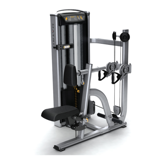
- Page 1 OWNERS MANUAL Versa Single-Station Strength VS-S34 Seated Row G1_OM_Seated Row Rev.1.1.indd 1 11/19/13 4:29 PM...
-
Page 2: Table Of Contents
Table Of Contents IMPORTANT SAFETY INFORMATION It is the sole responsibility of the purchaser of Matrix products to instruct all individuals, whether they are the end user or supervis- ing personnel on proper usage of the equipment. It is recommended that all users of Matrix exercise equipment be informed of the following information prior to its use. -
Page 3: Getting Started (Product Specifications)
IMPORTANT SAFETY INSTRUCTIONS GETTING STARTED EXERCISE PLACARD | PRODUCT SPECIFICATIONS | MAINTENANCE CHECKLIST WARNING: This product contains chemicals known to the State of Califor- EXERCISE PLACARD nia to cause cancer and birth defects or other reproductive harm. WARNING: SERIOUS INJURY CAN OCCUR ON THIS EQUIPMENT. FOLLOW THESE PRECAUTIONS TO AVOID INJURY! Never allow children on strength training equipment. -
Page 4: Markings
UNPACKING Thank you for purchasing a Matrix product. This machine is an EN957-1 and EN957-2 compliant Class S product. Your Ma- trix product is inspected before it is packaged. It is shipped in multiple pieces to facilitate the compact packaging of the machine. -
Page 5: Parts List
Parts List Parts List DESCRIPTION DESCRIPTION M10 X 125L Socket Head Cap Screw Bottom Pad M10 Flat Washer M10 X 20L Hex Bolt Wide Cupped Flange Foot Rest User Frame M10 X 80L Socket Head Cap Screw M10 Nylock Nut Front Shroud Lower Connecting Tube Rear Shroud... - Page 6 ASSEMBLY ASSEMBLY PART 2: CABLE ASSEMBLY PART 1: STACK & USER FRAME ASSEMBLY STEP 1 | WEIGHT STACK TO USER FRAME INSTRUCTIONS & NOTES STEP 1 | BOTTOM PULLEY ASSEMBLY INSTRUCTIONS & NOTES DESCRIPTION QUANTITY DESCRIPTION QUANTITY M10 X 125L SHC M10 Flat Washer M10 Flat Washer Cable Keeper...
-
Page 7: Part 2 Cable Assembly
ASSEMBLY ASSEMBLY PART 2: CABLE ASSEMBLY PART 2: CABLE ASSEMBLY STEP 2 | FLOATING PULLEY ASSEMBLY INSTRUCTIONS & NOTES STEP 3 | FLOATING PULLEY ASSEMBLY INSTRUCTIONS & NOTES DESCRIPTION QUANTITY DESCRIPTION QUANTITY Cable Retaining Clip M10 Flat Washer Floating Pulley Bracket M10 Nylock Nut Weight Stack Cable Pulley... - Page 8 ASSEMBLY ASSEMBLY PART 2: CABLE ASSEMBLY PART 2: CABLE ASSEMBLY STEP 5 | LEFT & RIGHT SWIVELLING PULLEY ASSEMBLY INSTRUCTIONS & NOTES STEP 4 | LEFT & RIGHT UPPER PULLEY ASSEMBLY INSTRUCTIONS & NOTES DESCRIPTION QUANTITY DESCRIPTION QUANTITY M10 Washer M10 Flat Washer M10 X 20L SHC Cable Keeper...
- Page 9 ASSEMBLY ASSEMBLY PART 2: CABLE ASSEMBLY PART 2: CABLE ASSEMBLY STEP 6 | USER CABLE ROUTING STEP 7 | HANDLE ASSEMBLY INSTRUCTIONS & NOTES DESCRIPTION QUANTITY Hand Grip Cable Clevis Plastic Bullet Cover Insert pin into clevis as shown. Line up pin to notches in bullet cover as shown below G1_OM_Seated Row Rev.1.1.indd 16-17 11/19/13 4:29 PM...
-
Page 10: Part 3 Pad Assembly
ASSEMBLY ASSEMBLY PART 2: CABLE ASSEMBLY PART 3: PAD ASSEMBLY STEP 7 | HANDLE ASSEMBLY INSTRUCTIONS & NOTES STEP 1 | CHEST PAD ASSEMBLY INSTRUCTIONS & NOTES DESCRIPTION QUANTITY DESCRIPTION QUANTITY M5 X 30L SHC M10 Flat Washer M5 Nylock Nut M10 X 20L SHC Chest Pad Chest Pad Back Cover... -
Page 11: Part 4 Foot Rest Assembly
ASSEMBLY ASSEMBLY PART 4: FOOT REST ASSEMBLY PART 3: PAD ASSEMBLY STEP 1 | FOOT REST ASSEMBLY ASSEMBLY INSTRUCTIONS & NOTES STEP 2 | BOTTOM PAD ASSEMBLY INSTRUCTIONS & NOTES DESCRIPTION QUANTITY DESCRIPTION QUANTITY Bottom Pad M10 Flat Washer M10 Nylock Nut M10 X 20L Hex Bolt Foot Rest M10 X 80L SHC... -
Page 12: Part 5 Plastics Assembly
ASSEMBLY ASSEMBLY PART 5: PLASTICS ASSEMBLY PART 5: PLASTICS ASSEMBLY STEP 2 | TOP CAP ASSEMBLY INSTRUCTIONS & NOTES STEP 1 | SHROUD ASSEMBLY ASSEMBLY INSTRUCTIONS & NOTES DESCRIPTION QUANTITY DESCRIPTION QUANTITY M8 X 25L SHC Front Shroud M8 Flat Washer (20 mm diameter) Rear Shroud (Not shown) Top Cap Position hangers in their lowest position... -
Page 13: Part 6 Cable Adjustment
ASSEMBLY ASSEMBLY PART 5: PLASTICS ASSEMBLY PART 6: CABLE ADJUSTMENT STEP 3 | TOP CAP COVERS INSTRUCTIONS & NOTES STEP 1 | CABLE ADJUSTMENT INSTRUCTIONS & NOTES DESCRIPTION QUANTITY Top Cap Cover Cable tension is adjusted by raising or lowering pulley as shown. Note: Nuts for adjustable pulley must be on inside towards weight plates. -
Page 14: Part 7 Premium Kit Assembly
ASSEMBLY ASSEMBLY PART 7: PREMIUM KIT ASSEMBLY PART 7: PREMIUM KIT ASSEMBLY STEP 1 | PREMIUM KIT ASSEMBLY INSTRUCTIONS & NOTES PREMIUM KIT ASSEMBLY INSTRUCTIONS & NOTES Rep Counter - Magnet DESCRIPTION QUANTITY Wing Rep Counter 1. Remove the (2) top cap covers using a flat blade screw Towel Hook driver. - Page 15 ASSEMBLY ASSEMBLY PART 7: PREMIUM KIT ASSEMBLY PART 7: PREMIUM KIT ASSEMBLY STEP 2 | PREMIUM KIT ASSEMBLY INSTRUCTIONS & NOTES STEP 3 | PREMIUM KIT ASSEMBLY INSTRUCTIONS & NOTES Rep Counter - Sensors Rep Counter 1. Assemble Rep Counter sensor base using (4) 1.
- Page 16 ASSEMBLY ASSEMBLY PART 7: PREMIUM KIT ASSEMBLY PART 7: PREMIUM KIT ASSEMBLY STEP 4 | PREMIUM KIT ASSEMBLY INSTRUCTIONS & NOTES STEP 5 | PREMIUM KIT ASSEMBLY INSTRUCTIONS & NOTES Grips Wing Assemble the wing (1P) as shown M8 hardware provided with the kit.
- Page 17 ASSEMBLY ASSEMBLY PART 7: PREMIUM KIT ASSEMBLY PART 7: PREMIUM KIT ASSEMBLY STEP 7 | PREMIUM KIT ASSEMBLY INSTRUCTIONS & NOTES STEP 6 | PREMIUM KIT ASSEMBLY INSTRUCTIONS & NOTES Gas Shock Pull Pin Raise the seat to the highest position before adding gas shock (6P) Shock must be positioned as shown with gas cylinder above piston rod...
- Page 18 G1_OM_Seated Row Rev.1.1.indd 34-35 11/19/13 4:29 PM...
- Page 19 Matrix Fitness 1600 Landmark Drive Cottage Grove WI 53527 matrixfitness.com Toll-free 866.693.4863 Facsimilie 608.839.8687 Versa Seated Row Owners Guide Rev.1.1 Copyright © 2013 Matrix Fitness G1_OM_Seated Row Rev.1.1.indd 36 11/19/13 4:29 PM...
Need help?
Do you have a question about the VS-S34 and is the answer not in the manual?
Questions and answers