Table of Contents
Advertisement
Advertisement
Table of Contents

Related Manuals for Matrix G7-S70


Summary of Contents for Matrix G7-S70
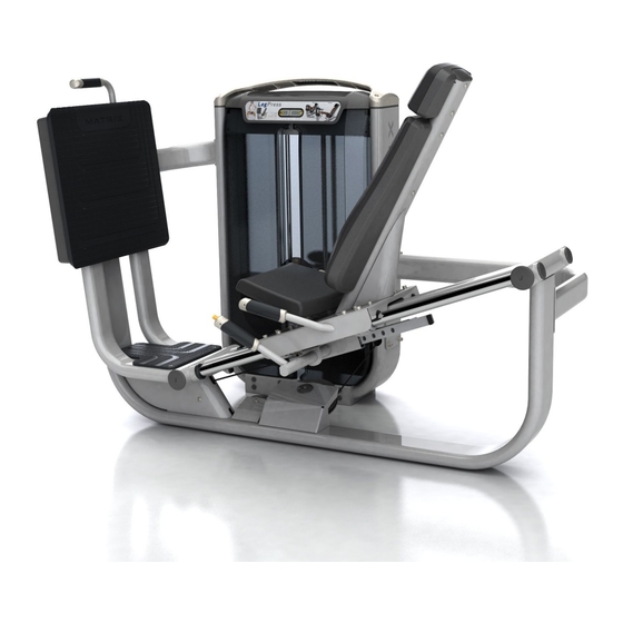
- Page 1 OWNERS MANUAL ULTRA Single-Station Strength G7-S70 Leg Press...
-
Page 2: Table Of Contents
Table Of Contents Safety, General Care & Maintenence ........................3 Getting Started (Product Specifications) ......................5 Assembly Information .............................6 Markings ..................................7 Parts List ...................................8 Installation & Assembly: Value Line Part 1 Weight Stack & Frame Assembly ....................10 Part 2 Cable Assembly ..........................13 Part 3 Seat Assembly .......................... -
Page 3: Safety, General Care & Maintenence
IMPORTANT SAFETY INSTRUCTIONS IMPORTANT SAFETY INFORMATION It is the sole responsibility of the purchaser of Matrix products to instruct all individuals, whether they are the end user or supervising personnel on proper usage of the equipment. It is recommended that all users of Matrix exercise equipment be informed of the following information prior to its use. - Page 4 IMPORTANT SAFETY INSTRUCTIONS WARNING: This product contains chemicals known to the State of California to cause cancer and birth defects or other reproductive harm. WARNING: SERIOUS INJURY CAN OCCUR ON THIS EQUIPMENT. FOLLOW THESE PRECAUTIONS TO AVOID INJURY! Never allow children on strength training equipment. Teenagers must be supervised at all times while using this equipment.
-
Page 5: Getting Started (Product Specifications)
GETTING STARTED EXERCISE PLACARD | PRODUCT SPECIFICATIONS | MAINTENANCE CHECKLIST EXERCISE PLACARD PRODUCT SPECIFICATIONS TECH SPECS Maximum User Weight 136 kg / 300 lbs. Maximum Training Weight 182 kg / 400 lbs. Product Weight 404 kg / 891 lbs. Overall Dimensions (L x W x H) 206.4 x 110.5 x 152.1 cm / 81.2"... -
Page 6: Assembly Information
Thank you for purchasing a Matrix product. This machine is an EN957-1 and EN957-2 compliant Class S product. Your Matrix product is inspected before it is packaged. It is shipped in multiple pieces to facilitate the compact packaging of the machine. -
Page 7: Markings
MARKINGS WARNING LABEL LOCATIONS Hazard warning sticker... -
Page 8: Parts List
Parts List DESCRIPTION Lower Connecting Tube M10 X 30L Socket Head Cap Screw M10 Flat Washer (25 mm Diameter) Weight Stack M10 Nylock Nut M10 X 75L Socket Head Cap Screw Upper Connecting Tube M10 X 170L Socket Head Cap Screw User Frame M10 Saddle Washer M10 X 25L Socket Head Cap Screw... -
Page 9: M10 X 30L Socket Head Cap Screw
Parts List DESCRIPTION M10 X 15L Socket Head Cap Screw Head Rest Assembly M10 X 75L Button Head Cap Screw Back Pad Assmembly Left Front Shroud Rear Shroud Right Front Shroud M8 X 60L Socket Head Cap Screw Top Cap... -
Page 10: Part 1 Weight Stack & Frame Assembly
ASSEMBLY PART 1: USER FRAME ASSEMBLY STEP 1 | WEIGHT STACK INSTRUCTIONS & NOTES DESCRIPTION QUANITY Lower Connecting Tube M10 X 30L SHC M10 Flat Washer (25 mm Diameter) Weight Stack M10 Nylock Nut M10 X 75L SHC Upper Connecting Tube Install the user frame hardware as shown, but DO NOT FULLY TIGHTEN . -
Page 11: User Frame
ASSEMBLY PART 1: USER FRAME ASSEMBLY STEP 2 | USER FRAME INSTRUCTIONS & NOTES DESCRIPTION QUANITY M10 X 30L SHC M10 Flat Washer (25 mm Diameter) M10 X 170L SHC User Frame M10 Saddle Washer 10 2 View A • Ensure that the frame is level and that all floor pads contact the floor equally • Install the frame hardware as shown, orienting the saddle washers as shown in View A. -
Page 12: M10 Flat Washer (22 Mm Diameter)
ASSEMBLY PART 1: USER FRAME ASSEMBLY STEP 3 | FOOT PLATE ASSEMBLY INSTRUCTIONS & NOTES DESCRIPTION QUANITY M10 Flat Washer (25 mm Diameter) M10 Nylock Nut M10 X 75L SHC M10 X 25L SHC M10 Flat Washer (22 mm Diameter) Footplate Assembly 6 13 Torque to 77 N-m/57 ft-lbs. -
Page 13: Part 2 Cable Assembly
ASSEMBLY PART 1: USER FRAME ASSEMBLY STEP 4 | FOOT PLATE COVER ASSEMBLY INSTRUCTIONS & NOTES DESCRIPTION QUANITY Footplate Cover M6 Flat Washer M6 X 16L BHC... -
Page 14: Cam
ASSEMBLY PART 2: CABLE ASSEMBLY STEP 1 | CAM & CABLE ASSEMBLY INSTRUCTIONS & NOTES DESCRIPTION QUANITY M10 Nylock Nut M10 Flat Washer (22 mm Diameter) M10 X 105L SHC CAM (W/User Frame Cable Attached) • Remove CAM plate • Assemble cable into CAM as shown • Capture cable end with retaining “U”... - Page 15 ASSEMBLY PART 2: CABLE ASSEMBLY STEP 2 | CABLE ASSEMBLY INSTRUCTIONS & NOTES Remove pulley to route cable inside cable keeper as shown and re-torque to 77 N-m/57 ft-lbs.
-
Page 16: Part 3 Seat Assembly
ASSEMBLY PART 3: SEAT ASSEMBLY STEP 1 | SEAT SLED ASSEMBLY INSTRUCTIONS & NOTES DESCRIPTION QUANITY M8 Flat Washer M8 Nylock Nut Linear Bearing Block M8 X 30L SHC Seat Sled Assemble bearings to sled as shown - DO NOT FULLY TIGHTEN... -
Page 17: Rubber Bumper Stop
ASSEMBLY PART 3: SEAT ASSEMBLY STEP 2 | SLED AND GUIDE ROD ASSEMBLY INSTRUCTIONS & NOTES DESCRIPTION QUANITY Seat Sled Rubber Bumper Stop Snap Ring Disc (45 mm Diameter) Guide Rod Sleeve Guide Rod Assemble guide rods onto sled as shown... -
Page 18: End Cap
ASSEMBLY PART 3: SEAT ASSEMBLY STEP 3 | SEAT GUIDE ROD ASSEMBLY INSTRUCTIONS & NOTES DESCRIPTION QUANITY Snap Ring Disc (45 mm Diameter) Guide Rod Sleeve Guide Rod End Cap • Assemble components as shown • Torque linear bearings from page 15 to 77 N-m/57 ft-lbs. - Page 19 ASSEMBLY PART 3: SEAT ASSEMBLY STEP 4 | ROM ASSEMBLY INSTRUCTIONS & NOTES DESCRIPTION QUANITY M10 Flat Washer (22 mm Diameter) ROM Assembly M10 X 20L SHC Assemble ROM assembly as shown. Tighten to 77 N-m/57 ft-lbs.
- Page 20 ASSEMBLY PART 3: SEAT ASSEMBLY STEP 5 | CABLE TO SEAT SLED ASSEMBLY INSTRUCTIONS & NOTES DESCRIPTION QUANITY M8 Nylock Nut M8 Shoulder Bolt • Remove lower foot plate to gain access to lower pulley and cable end • Assemble cable end as show • Torque shoulder bolt to: 16 N-m/142 in-lbs.
-
Page 21: Part 4 Pad Assembly
ASSEMBLY PART 4: PAD ASSEMBLY STEP 1 | PAD ASSEMBLY INSTRUCTIONS & NOTES DESCRIPTION QUANITY M10 X 15L SHC Orient the pad as shown. Tighten to 27 N-m/20 ft-lbs. - Page 22 ASSEMBLY PART 4: PAD ASSEMBLY STEP 2 | BACK PAD & HEAD PAD ASSEMBLY INSTRUCTIONS & NOTES DESCRIPTION QUANITY Head Rest Assembly M10 X 75L BHC Back Pad Assembly Install the pad as shown. Tighten to 27 N-m/20 ft-lbs.
-
Page 23: Part 5 Plastics Assembly
ASSEMBLY PART 5: PLASTICS ASSEMBLY STEP 1 | SHROUD ASSEMBLY ASSEMBLY INSTRUCTIONS & NOTES DESCRIPTION QUANITY Left Front Shroud Rear Shroud Right Front Shroud Install the weight stack shrouds as shown. - Page 24 ASSEMBLY PART 5: PLASTICS ASSEMBLY STEP 2 | TOP CAP ASSEMBLY INSTRUCTIONS & NOTES DESCRIPTION QUANITY M8 X 60L SHC Top Cap Install the top cap and connect rep counter I M PO RTA NT NOTI CE plug as shown. Torque to 17 N-m/147 in-lbs.
- Page 25 Matrix Fitness 1600 Landmark Drive Cottage Grove WI 53527 matrixfitness.com Toll-free 866.693.4863 Facsimilie 608.839.8687 ULTRA Leg Press Owners Guide rev.1.2 Copyright© 2014 Matrix Fitness...
Need help?
Do you have a question about the G7-S70 and is the answer not in the manual?
Questions and answers