Advertisement
Table of Contents
- 1 Table of Contents
- 2 Safety, General Care & Maintenence
- 3 Getting Started (Product Specifications)
- 4 Assembly Information
- 5 Markings
- 6 Parts List
- 7 Installation & Assembly: Value Line Part 1 Weight Stack to User Frame Assembly
- 8 Part 2 Weight Stack Cable Assembly
- 9 Part 3 Lower Right Arm Assembly
- 10 Part 4 Lower Left Arm Assembly
- 11 Part 5 User Frame Cable Assembly
- 12 Part 6 Upper Arm Assembly
- 13 Part 7 Pad Assembly
- 14 Part 8 Plastics Assembly
- 15 Part 9 Premium Kit Assembly
- 16 Weight Stack Frame
- Download this manual
Advertisement
Table of Contents

Related Manuals for Matrix VS-S22


Summary of Contents for Matrix VS-S22
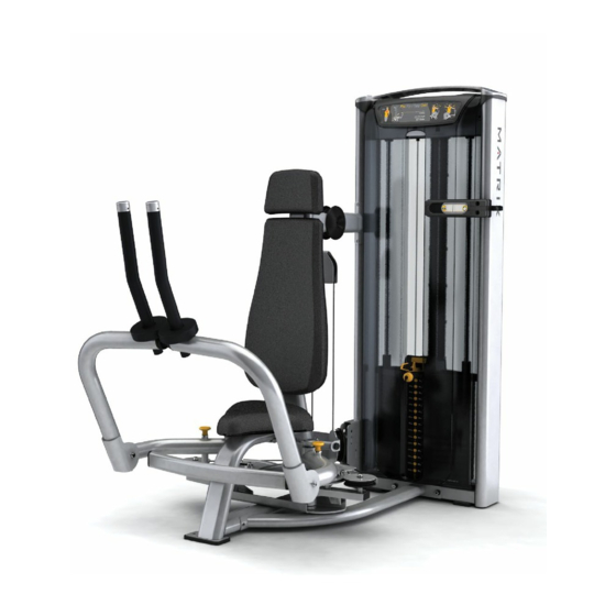
- Page 1 OWNERS MANUAL Versa Single-Station Strength VS-S22 Pec Fly/Rear Delt...
-
Page 2: Table Of Contents
Table Of Contents Safety, General Care & Maintenence ..........3 Getting Started (Product Specifications) ........5 Assembly Information ...............6 Markings ....................7 Parts List .....................8 Installation & Assembly: Value Line Part 1 Weight Stack to User Frame Assembly .......10 Part 2 Weight Stack Cable Assembly ..........11 Part 3 Lower Right Arm Assembly ..........12 Part 4 Lower Left Arm Assembly ............4 Part 5 User Frame Cable Assembly ..........16... -
Page 3: Safety, General Care & Maintenence
IMPORTANT SAFETY INSTRUCTIONS IMPORTANT SAFETY INFORMATION It is the sole responsibility of the purchaser of Matrix products to instruct all individuals, whether they are the end user or supervising personnel on proper usage of the equipment. It is recommended that all users of Matrix exercise equipment be informed of the following information prior to its use. - Page 4 IMPORTANT SAFETY INSTRUCTIONS WARNING: This product contains chemicals known to the State of California to cause cancer and birth defects or other reproductive harm. WARNING: SERIOUS INJURY CAN OCCUR ON THIS EQUIPMENT. FOLLOW THESE PRECAUTIONS TO AVOID INJURY! Never allow children on strength training equipment. Teenagers must be supervised at all times while using this equipment.
-
Page 5: Getting Started (Product Specifications)
GETTING STARTED EXERCISE PLACARD | PRODUCT SPECIFICATIONS | MAINTENANCE CHECKLIST EXERCISE PLACARD PRODUCT SPECIFICATIONS TECH SPECS Overall dimensions 60”L X 60”W X 66”H Light Stack = 492 lbs (224 kg), Heavy Stack = 542 lbs (256 Weight Shipping weight 342 lbs (156kg) WARRANTY (Valid in USA only) Frame (not coatings) 10 years... -
Page 6: Assembly Information
Thank you for purchasing a Matrix product. This machine is an EN957-1 and EN957-2 compliant Class S product. Your Matrix product is inspected before it is packaged. It is shipped in multiple pieces to facilitate the compact packaging of the machine. -
Page 7: Markings
MARKINGS WARNING LABEL LOCATIONS... -
Page 8: Parts List
Parts List DESCRIPTION M10 X 125L Socket Head Cap Screw M10 Flat Washer Wide Cupped Flange M10 Nylock Nut Lower Connecting Tube M10 X 20L Socket Head Cap Screw User Frame Upper Connecting Tube Weight Stack Frame M10 X 50L Socket Head Cap Screw Cable Retaining Clip Weight Stack Cable Pulley... - Page 9 Parts List DESCRIPTION M10 X 15L Socket Head Cap Screw Upper Left Arm Assembly M10 X 75L Socket Head Cap Screw Head Pad Back Pad M10 X 20L Hex Bolt Front Shroud Rear Shroud M8 X 25L SHC Large M8 Flat Washer (Ø20 mm) Top Cap Top Cap Cover PREMIUM KIT COMPONENTS...
-
Page 10: Installation & Assembly: Value Line Part 1 Weight Stack To User Frame Assembly
ASSEMBLY PART 1: USER FRAME ASSEMBLY STEP 1 | USER FRAME TO WEIGHT STACK ASSEMBLY INSTRUCTIONS & NOTES DESCRIPTION QUANTITY M10 X 125L SHC M10 Flat Washer Wide Cupped Flange M10 Nylock Nut Lower Connecting Frame M10 X 20 SHC User Frame Upper Connecting Frame Weight Stack Frame... -
Page 11: Part 2 Weight Stack Cable Assembly
ASSEMBLY PART 2: WEIGHT STACK CABLE ASSEMBLY STEP 1 | FLOATING PULLEY ASSEMBLY INSTRUCTIONS & NOTES DESCRIPTION QUANTITY M10 Flat Washer M10 Nylock Nut M10 X 50L SHC Cable Retaining Clip Weight Stack Cable Pulley Floating Pulley Bracket... -
Page 12: Part 3 Lower Right Arm Assembly
ASSEMBLY PART 3: LOWER RIGHT ARM ASSEMBLY STEP 1 | RIGHT ARM TO FRAME ASSEMBLY INSTRUCTIONS & NOTES DESCRIPTION QUANTITY Lower Right Arm Assembly Wave (Spring) Washer Right CAM Assembly Ø Axle ( 20 X 250L) Ø Ø Spacer ( 45 mm OD/ 30 mm ID) Right Side Swingarm Assembly... - Page 13 ASSEMBLY PART 3: LOWER RIGHT ARM ASSEMBLY STEP 2 | RIGHT ARM TO USER FRAME ASSEMBLY INSTRUCTIONS & NOTES DESCRIPTION QUANTITY Axle Locking Sleeve M5 X 10L SHC M5 Flat Washer M5 X 16L SHC Tighten to 7 N-m/5 ft-lbs. to lock axle in place Press item 21 in place to lock the assembly.
-
Page 14: Part 4 Lower Left Arm Assembly
ASSEMBLY PART 4: LOWER LEFT ARM ASSEMBLY STEP 1 | LEFT ARM TO FRAME ASSEMBLY INSTRUCTIONS & NOTES DESCRIPTION QUANTITY Wave (Spring) Washer Ø Axle ( 20 X 250L) Ø Ø Spacer ( 26.5 mm OD/ 20.5 mm ID) Lower Left Arm Assembly Left CAM Assembly Left Side Swingarm Assembly Assemble components in the order shown and slide assembly into place. - Page 15 ASSEMBLY PART 4: LOWER LEFT ARM ASSEMBLY STEP 2 | LEFT ARM TO USER FRAME ASSEMBLY INSTRUCTIONS & NOTES DESCRIPTION QUANTITY Axle Locking Sleeve M5 X 10L SHC M5 Flat Washer M5 X 16L SHC Tighten to 7 N-m/5 ft-lbs. to lock axle in place Press item 21 in place to lock the assembly.
-
Page 16: Part 5 User Frame Cable Assembly
ASSEMBLY PART 5: USER FRAME CABLE ASSEMBLY STEP 1 | USER FRAME CABLE ASSEMBLY INSTRUCTIONS & NOTES DESCRIPTION QUANTITY User Frame Cable... -
Page 17: Part 6 Upper Arm Assembly
ASSEMBLY PART 6: UPPER ARM ASSEMBLY STEP 1 | UPPER ARMS TO USER FRAME ASSEMBLY INSTRUCTIONS & NOTES DESCRIPTION QUANTITY M10 Flat Washer Upper Right Arm Assembly M10 Flat Washer (35 mm Diameter) Ø Axle ( 25 X 69.4L) M10 X 15L SHC Upper Left Arm Assembly Locate knurled end of axles and large washers as shown... - Page 18 ASSEMBLY PART 6: UPPER ARM ASSEMBLY STEP 2 | UPPER ARMS LIMIT ADJUSTMENTS INSTRUCTIONS & NOTES 115 Deg Outer Limit 90 Deg 90 Deg Inner Limit See Detail A on page 19 Note: Outer limit position maintains a clearance of 35 mm between each arm and the front weight stack shroud...
- Page 19 ASSEMBLY PART 6: UPPER ARM ASSEMBLY STEP 2 | UPPER ARMS LIMIT ADJUSTMENTS INSTRUCTIONS & NOTES Detail A Loosen jam nut to make limit adjustment, and then Inner Limit Set Screw retighten Outer Limit Set Screw...
-
Page 20: Part 7 Pad Assembly
ASSEMBLY PART 7: PAD ASSEMBLY STEP 1 | BACK PAD ASSEMBLY INSTRUCTIONS & NOTES DESCRIPTION QUANTITY M10 Flat Washer M10 X 75L SHC Head Pad Back Pad Install the pad as shown. Tighten to 27 N-m/20 ft-lbs. - Page 21 ASSEMBLY PART 7: PAD ASSEMBLY STEP 2 | PAD ASSEMBLY INSTRUCTIONS & NOTES DESCRIPTION QUANTITY M10 X 20L Hex Bolt Install the pad as shown. Tighten to 27 N-m/20 ft-lbs.
-
Page 22: Part 8 Plastics Assembly
ASSEMBLY PART 8: PLASTICS ASSEMBLY STEP 1 | SHROUD ASSEMBLY ASSEMBLY INSTRUCTIONS & NOTES DESCRIPTION QUANTITY Front Shroud Rear Shroud (Not shown) Position hangers in their lowest position Install the weight stack shrouds as shown. - Page 23 ASSEMBLY PART 8: PLASTICS ASSEMBLY STEP 2 | TOP CAP ASSEMBLY INSTRUCTIONS & NOTES DESCRIPTION QUANTITY M8 X 25L SHC M8 Flat Washer (20 mm diameter) Top Cap Install the top cap onto the weight stack as shown. Torque to 17 N-m/147 in-lbs. Position top cap so that the instructional placard faces the user.
- Page 24 ASSEMBLY PART 8: PLASTICS ASSEMBLY STEP 3 | TOP CAP COVERS INSTRUCTIONS & NOTES DESCRIPTION QUANTITY Top Cap Cover Install the top cap covers.
-
Page 25: Part 9 Premium Kit Assembly
ASSEMBLY PART 9: PREMIUM KIT ASSEMBLY PREMIUM KIT ASSEMBLY INSTRUCTIONS & NOTES DESCRIPTION QUANTITY Wing Rep Counter Towel Hook Premium Pullpin I M PO RTA NT NOTI CE PLEASE NOTE: Be sure to remove the insulating sheet when installing the Rep Counter. -
Page 26: Weight Stack Frame
ASSEMBLY PART 9: PREMIUM KIT ASSEMBLY STEP 1 | PREMIUM KIT ASSEMBLY INSTRUCTIONS & NOTES Rep Counter - Magnet 1. Remove the (2) top cap covers (Item 59) using a flat blade screw driver. 2. Remove the (4) M8 bolts and 20 mm diameter washers that hold the top cap to the weight stack frame. - Page 27 ASSEMBLY PART 9: PREMIUM KIT ASSEMBLY STEP 2 | PREMIUM KIT ASSEMBLY INSTRUCTIONS & NOTES Rep Counter - Sensors 1. Assemble Rep Counter sensor base using (4) screws included with the kit. 2. Assemble (3) sensors located per machine chart shown below. Thread zip ties through holes to secure cables Route wires in groove...
- Page 28 ASSEMBLY PART 9: PREMIUM KIT ASSEMBLY STEP 3 | PREMIUM KIT ASSEMBLY INSTRUCTIONS & NOTES Rep Counter 1. Remove and discard hole caps using caution not to scratch the paint. 2. Attach plug to Rep Counter. 3. Assemble Towel Hook (3P) and Rep Counter (2P) using the M8 X 35L SHC bolts provided.
- Page 29 ASSEMBLY PART 9: PREMIUM KIT ASSEMBLY STEP 4 | PREMIUM KIT ASSEMBLY INSTRUCTIONS & NOTES Wing 1. Assemble the wing (1P) as shown. 2. Re-use the M8 bolts (Item 56) that were removed in step 1 and torque the wing hardware to 51N-m (37.6 ft-lbs.).
- Page 30 ASSEMBLY PART 9: PREMIUM KIT ASSEMBLY STEP 6 | PREMIUM KIT ASSEMBLY INSTRUCTIONS & NOTES Pull Pin Remove the two pull pins using an adjustable wrench, and replace with the Pre- mium pull pins (4P).
- Page 32 Matrix Fitness 1600 Landmark Drive Cottage Grove WI 53527 matrixfitness.com Toll-free 866.693.4863 Facsimilie 608.839.8687 Versa Pec Fly/Rear Delt Owners Guide Rev.1.2 Copyright© 2013 Matrix Fitness...
Need help?
Do you have a question about the VS-S22 and is the answer not in the manual?
Questions and answers