Advertisement
WM5-50
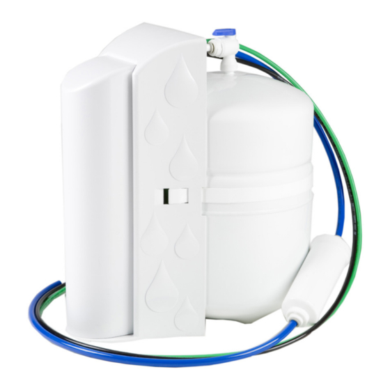
5-Stage Reverse Osmosis System
System tested and certified by NSF International
against NSF/ANSI Standard 58 for the reduction of
substances specified on the performance data sheet.
42445 Avenida Alvarado
Temecula, CA 92590
800-451-9343, FAX 951-894-2801
www.nimbuswater.com
42445 Avenida Alvarado, Temecula, CA 92590
(800) 451-9343 · www.nimbuswater.com
1
Rev: 10/14
Advertisement
Table of Contents

Related Manuals for Nimbus Water Systems WaterMaker Five WM5-50


Summary of Contents for Nimbus Water Systems WaterMaker Five WM5-50
- Page 1 WM5-50 5-Stage Reverse Osmosis System System tested and certified by NSF International against NSF/ANSI Standard 58 for the reduction of substances specified on the performance data sheet. 42445 Avenida Alvarado Temecula, CA 92590 800-451-9343, FAX 951-894-2801 www.nimbuswater.com 42445 Avenida Alvarado, Temecula, CA 92590 Rev: 10/14 (800) 451-9343 ·...
- Page 2 Please fill out the following information at the time of installation. Save for future reference. WaterMaker Five WM5-50 Model: Date Code: Install Date: Sold by: Installed By: Service Center Phone Number:...
- Page 3 Introduction to the WaterMaker Five Congratulations on your purchase of the WaterMaker Five reverse osmosis system. The WaterMaker Five features a four-stage prefilter, membrane and postfilter housed in a single cartridge. The fifth stage, an in-line carbon filter, is placed between tank and faucet.
-
Page 4: Limited Warranty
Limited Warranty This Limited Warranty extends to the original purchaser of the system only. This warranty covers all Manufacturer-supplied items only that prove to be defective in material, workmanship or factory preparation. This warranty covers parts only; all labor is excluded from this war- ranty, including, but not limited to, services related to the removal, replacement, installation, adjustment, maintenance and/or repair of the unit or its components items. -
Page 5: Performance Data Sheet
Performance Data Sheet System Performance This system has been tested according to NSF/ANSI 58 for reduction of the substances listed below. The concentration of the indicated substances in water leaving the system was reduced to a concentration less than or equal to the permissible limit for water leaving the system, as specified in NSF/ANSI 58. -
Page 6: Arsenic Fact Sheet
Arsenic Fact Sheet Arsenic (AS) is a natually occuring contaminant found in many ground waters. Arsenic in water has no color, taste or odor. It must be measured by a lab test. Public water utilities must have their water tested for arsenic. You can get the results from your water utility. - Page 7 TF50 (4 stage cartridge) 104592 GAC postfilter 104803 Manufacturer: Nimbus Water Systems The water treatment device(s) listed on this certificate have met the testing requirements pursuant to Section 116830 of the Health and Safety Code for the following health related contaminants:...
-
Page 8: System Specifications
System Specifications Dimensions and Weight System - 9.75” W x 13.5” D x 15.5” H ( 24.8 x 34.3 x 39.4 cm), 11 lbs. (5 kg.) Shipping Box - 14.5"L x 11.25"W x 20"H (36.8 x 28.6 x 50.8 cm), 13.7 lbs. (6.2 kg.) A. - Page 9 Push Handle Airgap Faucet Note: This faucet requires a 1¼" opening in the sink or countertop. 1. Locate the faucet parts bag and arrange the parts on the countertop in the sequence shown. 2. The last part in the sequence, the quick connect adapter (6), Installation Videos will be found in the smaller parts bag.
- Page 10 Feed and Drain Connection Feed Connection 1. Locate and turn off the angle stop valve on the cold water line feeding the sink. This valve will usually be located under the sink on the pipe coming out of the wall. 2.
- Page 11 System Activation and Flushing System Activation and Inspection 1. Check all tubing connections to ensure they are firmly seated. CHECK TO SEE THAT THE CARTRIDGE RETAINER CLIP IS PROPERLY ENGAGED AND LOCKED. Failure to keep the retaining clip in place will result in accidental leaks and flooding. 2.
-
Page 12: Installation Checklist
Installation Checklist 1. System is located where it will not be subject to physical impacts or rough contact by heavy objects. 2. Feed water pressure to the unit is no less than 40 psi and no greater than 80 PSI. 3. -
Page 13: Maintenance
Maintenance Cartridge Replacement 1. Close the small shut-off valve on the feed valve assembly. 2. Close the tank shut-off valve. 3. Open the dispensing faucet to relieve system pressure. Close dispensing faucet when flow has stopped. Remove the cover from the front of the system. Remove the retaining clip. Pull the cartridge off the system evenly at top and bottom.
Need help?
Do you have a question about the WaterMaker Five WM5-50 and is the answer not in the manual?
Questions and answers
My Water Maker system makes a CONSTANT gurgling noise. How do I fix that?
A constant gurgling noise in the Nimbus Water Systems WaterMaker Five WM5-50 may indicate an issue with water flow through the air gap, improper flushing, or incomplete tank filling. To address this:
1. Ensure the tank is fully filled and allowed to sit undisturbed for at least 8 hours after installation or maintenance.
2. Open the dispensing faucet fully and flush the system at maximum flow until the water runs clear and the chlorination scent is gone.
3. Flush and refill the tank at least three times to remove trapped air and residual sanitizing agents.
4. Check that the system is properly installed and not subject to physical impacts that could affect flow or cause noise.
If the noise continues, inspect for any blockages or improper installation in the drain line or air gap.
This answer is automatically generated
do you have a video how to change the filters?