
Related Manuals for Nimbus Water Systems WaterMaker Five


Summary of Contents for Nimbus Water Systems WaterMaker Five
- Page 1 5-Stage Reverse Osmosis System 41840 McAlby Court, Suite A Murrieta, CA 92562 800-451-9343, FAX 951-894-2801 www.nimbuswater.com 41840-A McAlby Court, Murrieta, CA 92562 02/09 (800) 451-9343, email: sales@nimbuswater.com...
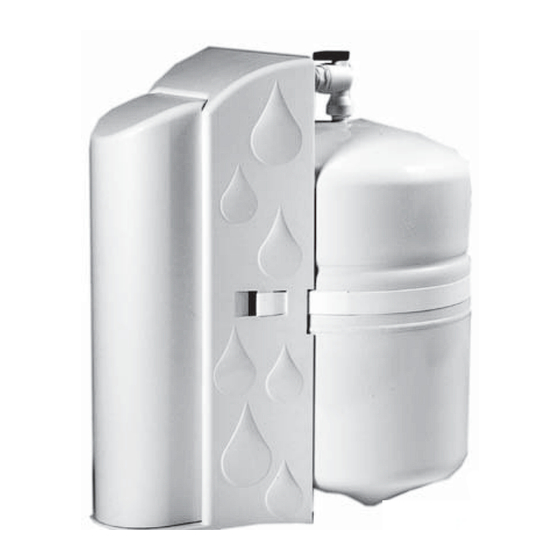
- Page 2 Introducti on to the WaterMaker Five Congratulati ons on your purchase of the WaterMaker Five reverse osmosis system. The WaterMaker Five features a four-stage prefi lter, membrane and postf ilter housed in a single cartridge. The fi ft h stage, an in-line carbon fi lter, is placed between tank and faucet.
-
Page 3: Warranty
Other Rights This Warranty gives you specifi c legal rights and you may also have other rights which vary from state to state. Please fi ll out the form below and retain for future reference. WaterMaker Five Model: Date Code:... -
Page 4: System Specifications
System Specifi cati ons Performance Specifi cati ons Feed Water Requirements Membrane System w/Tank Pressure 40-80 psi (275 kPa - 552 kPa) Temp 40°F - 100°F (4°C - 38°C) Producti on 40 GPD 21.6 GPD <2000 mg/L (151 LPD) (81.8 LPD) Chlorine <1.0 mg/L TDS Rejecti on... - Page 5 Push Handle Airgap Faucet Determine the most practi cal under-the-sink locati on for placement of the WaterMaker Five system. Ensure that the locati on allows adequate access for cartridge re placement. 1. Place the system in the selected locati on.
- Page 6 Feed and Drain Connecti on Feed Connecti on 1. Locate and turn off the angle stop valve on the cold water line feeding the sink. This valve will usually be located under the sink on the pipe coming out of the wall. 2.
- Page 7 System Acti vati on and Flushing System Acti vati on and Inspecti on 1. Check all tubing connecti ons to ensure they are fi rmly seated. CHECK TO SEE THAT THE CARTRIDGE RETAINER CLIP IS PROPERLY ENGAGED AND LOCKED. Failure to keep the retaining clip in place will result in accidental leaks and fl ooding. 2.
-
Page 8: Installation Checklist
Installati on Checklist 1. System is located where it will not be subject to physical impacts or rough contact by heavy objects. 2. Feed water pressure to the unit is no less than 40 psi and no greater than 80 PSI. 3. -
Page 9: Maintenance
Maintenance Cartridge Replacement Close the feed water shut-off valve. 2. Close the tank shut-off valve. Open the dispensing faucet to relieve system pressure. Close dispensing faucet when fl ow has stopped. Remove the cover from the front of the system. Remove the retaining clip. Pull the cartridge off the system evenly at top and bott om.
Need help?
Do you have a question about the WaterMaker Five and is the answer not in the manual?
Questions and answers