
Related Manuals for Nimbus Water Systems Five Water Maker WM5-50


Summary of Contents for Nimbus Water Systems Five Water Maker WM5-50
-
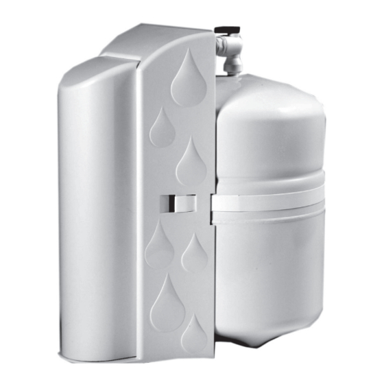
Page 1: Stage Reverse Osmosis System
5-Stage Reverse Osmosis System WM5-50 41840 McAlby Court, Suite A Murrieta, CA 92562 800-451-9343, FAX 951-894-2801 www.nimbuswater.com 41840-A McAlby Court, Murrieta, CA 92562 10/10 (800) 451-9343, email: sales@nimbuswater.com... - Page 2 Introduction to the WaterMaker Five Congratulations on your purchase of the WaterMaker Five reverse osmosis system. When properly maintained, this system will provide you with years of trouble-free service. The next sections contain important information on the proper care and maintenance of your system, please take a few minutes to read through this information.
-
Page 3: Warranty
Warranty The Limited Warranty extends to the original purchaser of the system. This warranty covers all parts and factory labor needed to repair any Manufacturer-supplied item that proves to be defective in material, workman ship or factory preparation. The above-mentioned warranty ap plies for the first full calender year from date of purchase. -
Page 4: System Specifications
System Specifications Performance Specifications Feed Water Requirements Membrane System w/Tank Pressure 40-80 psi (275 kPa - 552 kPa) Temp 40°F - 100°F (4°C - 38°C) Production 50 GPD 27 GPD <2000 mg/L (189 LPD) (102 LPD) Chlorine <1.0 mg/L TDS Rejection Turbidity <1 NTU Recovery... - Page 5 Push Handle Airgap Faucet 1. Insert polished faucet base and rubber seal onto base of faucet and insert base assembly down through the sink hole. 2. From underneath the sink, push the 1/4” black drain tubing attached to the system onto the 1/4” fitting located on the faucet base.
- Page 6 Feed and Drain Connection Feed Connection 1. Locate and turn off the angle stop valve on the cold water line feeding the sink. This valve will usually be located under the sink on the pipe coming out of the wall. 2.
- Page 7 System Activation and Flushing System Activation and Inspection 1. Check all tubing connections to ensure they are firmly seated. CHECK TO SEE THAT THE CARTRIDGE RETAINER CLIP IS PROPERLY ENGAGED AND LOCKED. Failure to keep the retaining clip in place will result in accidental leaks and flooding. 2.
-
Page 8: Installation Checklist
Installation Checklist 1. System is located where it will not be subject to physical impacts or rough contact by heavy objects. 2. Feed water pressure to the unit is no less than 40 psi and no greater than 80 PSI. 3. -
Page 9: Maintenance
Maintenance Cartridge Replacement Close the feed water shut-off valve. Close the tank shut-off valve. Open the dispensing faucet to relieve system pressure. Close dispensing faucet when flow has stopped. Remove the cover from the front of the system. Remove the retaining clip. Pull the cartridge off the system evenly at top and bottom.
Need help?
Do you have a question about the Five Water Maker WM5-50 and is the answer not in the manual?
Questions and answers