
Related Manuals for ADLINK Technology EOS-1200


Summary of Contents for ADLINK Technology EOS-1200
- Page 1 EOS-1200 4-CH Gigabit PoE Embedded Vision System User’s Manual 2.00 Manual Rev.: Dec. 28, 2011 Revision Date: 50-1Z111-2000 Part No: Advance Technologies; Automate the World.
-
Page 2: Revision History
Revision History Revision Release Date Description of Change(s) 2.00 Dec. 28, 2011 Initial release... -
Page 3: Preface
EOS-1200 Preface Copyright 2011 ADLINK Technology Inc. This document contains proprietary information protected by copy- right. All rights are reserved. No part of this manual may be repro- duced by any mechanical, electronic, or other means in any form without prior written permission of the manufacturer. - Page 4 Conventions Take note of the following conventions used throughout this manual to make sure that users perform certain tasks and instructions properly. Additional information, aids, and tips that help users perform tasks. NOTE: NOTE: Information to prevent minor physical injury, component dam- age, data loss, and/or program corruption when trying to com- plete a task.
-
Page 5: Table Of Contents
EOS-1200 Table of Contents Revision History..............ii Preface ..................iii List of Figures ................ ix List of Tables................xi 1 Introduction ................ 1 Overview................1 Features................1 Specifications............... 2 Unpacking Checklist ............4 2 System Description............5 Schematics ................5 Front Panel I/O Connectors .......... - Page 6 2.3.4 Rear Panel Digital I/O ..........17 Internal I/O connectors............19 2.4.1 Clear CMOS and ME RTC register Jumpers.... 20 2.4.2 DC 12V Fan Connector ..........20 2.4.3 DC 12V Fan Connector (reserved) ......20 2.4.4 USB 2.0 Type A Connector ........20 2.4.5 SUMIT Connector .............
- Page 7 EOS-1200 List of Functions..............39 Data Types................ 40 Setting Up the Build Environment........40 5.3.1 Include Files ............. 40 5.3.2 Library Files .............. 41 5.3.3 DLL Files ..............41 System & Initialization Functions ........42 5.4.1 Register_Card ............42 5.4.2...
- Page 8 5.8.3 EEPROM_WriteBytes..........69 6 BIOS Setup ................ 71 Main ................... 72 6.1.1 System Time/System Date ........72 Advanced ................73 6.2.1 ACPI Settings ............74 6.2.2 CPU Configuration............ 75 6.2.3 Onboard Device Configuration ......... 77 6.2.4 Advanced Power Management......... 78 6.2.5 SATA Configuration ..........
-
Page 9: List Of Figures
Figure 2-2: EOS-1200 Rear View ............5 Figure 2-3: EOS-1200 Top View ............6 Figure 2-4: EOS-1200 Right Side View..........6 Figure 2-5: EOS-1200 Left Side View ..........6 Figure 2-6: Front Panel I/O Connectors ..........7 Figure 2-7: Gigabit Ethernet Ports ........... 10 Figure 2-8: DVI-I connector.............. - Page 10 This page intentionally left blank. List of Figures...
-
Page 11: List Of Tables
EOS-1200 List of Tables Table 1-1: EOS-1200 General Specifications ........2 Table 2-1: Front Panel I/O Connector Legend........7 Table 2-2: LED Indicators ..............8 Table 2-3: Gigabit Ethernet Port Features ........9 Table 2-4: Active/Link LED ............. 10 Table 2-5: Speed LED ..............10 Table 2-6: DVI-I Connector Signals .......... - Page 12 This page intentionally left blank. List of Tables...
-
Page 13: Introduction
EOS-1200 Introduction 1.1 Overview ADLINK’s EOS-1200 is a rugged embedded vision system that features four independent Gigabit PoE (power over Ethernet) ports in a compact 220mm (W) x 80 mm (H) x 200 mm (D) small ® form factor chassis, with 2nd Generation Intel Core™... -
Page 14: Specifications
1x PS/2 for keyboard and mouse (requires S3 KB/MS wakeup) Power Supply Built-in 9-32 VDC wide-range DC 3P pluggable DC Input connector with latch (GND, V-, V+) AC Input Optional 150 W external AC-DC adapter Table 1-1: EOS-1200 General Specifications Introduction... - Page 15 5 Grms, 5-500 Hz, 3 axes Vibration 3 Grms, 5-500 Hz, 3 axes (Operating) 0.5 Grms, 5-500 Hz, 3 axes Operating, 30 Grms, half sine 11ms duration Shock (CF or SSD) CE, FCC Class A Table 1-1: EOS-1200 General Specifications Introduction...
-
Page 16: Unpacking Checklist
Retain the shipping carton and packing materials for inspection. Obtain authorization from your dealer before returning any product to ADLINK. Ensure that the fol- lowing items are included in the package. EOS-1200 unit Wall mounting brackets (x2) Mounting M4, 8mm screws (x4) PS/2 Y cable... -
Page 17: System Description
EOS-1200 System Description This chapter describes appearance and connection of the EOS-1200, including chassis dimensions and front panel and internal I/O connectors 2.1 Schematics All units are in millimeters (mm) NOTE: NOTE: Figure 2-1: EOS-1200 Front View Figure 2-2: EOS-1200 Rear View... -
Page 18: Figure 2-3: Eos-1200 Top View
Figure 2-3: EOS-1200 Top View Figure 2-4: EOS-1200 Right Side View Figure 2-5: EOS-1200 Left Side View System Description... -
Page 19: Front Panel I/O Connectors
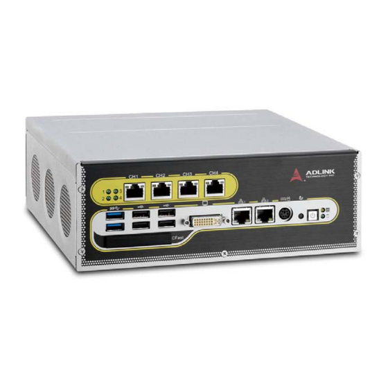
EOS-1200 2.2 Front Panel I/O Connectors The EOS-1200 provides I/O connection on the front panel, as fol- lows. Figure 2-6: Front Panel I/O Connectors LED indicators Power switch Reset switch PS/2 keyboard & mouse Dual Gigabit Ethernet ports DVI-I connector USB 2.0 connectors x4 (Type A) -
Page 20: Led Indicators
2.2.3 Reset Button The reset button executes a hard reset. 2.2.4 PS/2 Connector The EOS-1200 provides connectors for PS/2 keyboard and mouse, either singly or with a Y-cable to connect both at the same time. System Description... -
Page 21: Dual Gigabit Ethernet Ports
EOS-1200 2.2.5 Dual Gigabit Ethernet Ports The EOS-1200 provides two Gigabit Ethernet ports on the front panel, an Intel® 82574IT Gigabit Ethernet Controller and Intel® 82579LM Gigabit Ethernet PHY, with features as follows. Intel® 82574IT Gigabit Ethernet Intel® 82579LM Gigabit Ethernet... -
Page 22: Dvi-I Connector
1000 Mbps Table 2-5: Speed LED 2.2.6 DVI-I connector The EOS-1200 provides one DVI-I connector for connection to an external monitor. The DVI-I connector can be separated into VGA and DVI-D (single link) interfaces. Figure 2-8: DVI-I connector System Description... -
Page 23: Usb 2.0 Connectors
Table 2-6: DVI-I Connector Signals 2.2.7 USB 2.0 Connectors The EOS-1200 provides four Type A USB 2.0 ports on the front panel. All are compatible with Hi-Speed, full-speed, and low-speed USB devices. The EOS-1200 supports multiple boot devices, including USB flash, USB external HD, USB floppy, and USB CD-ROM drives. -
Page 24: Cfast Slot
NOTE: 2.2.9 CFast Slot The EOS-1200 is equipped with a type II push-push CFast host connector on the front panel, connecting to the host controller by SATA interface. Data transfer rates up to 3.0Gb/s(300MB/s)/ 1.5Gb/s(150MB/s) are supported. The host SATA controller pro- vides a legacy operating mode using I/O space, and an AHCI operating mode using memory space. -
Page 25: Table 2-7: Poe Port Connections Legend
EOS-1200 Signal MDI0+ MDI0- MDI1+ MDI2+ MDI2- MDI1- MDI3+ MDI3- Table 2-7: PoE Port Connections Legend Power over Ethernet support includes: • Four fully-integrated Gigabit Ethernet Media Access Control (MAC) and physical layer (PHY) ports • Compliance with IEEE 802.3.af standard for a maximum of 8 W/... -
Page 26: Rear Panel I/O Connectors
2.3 Rear Panel I/O Connectors The EOS-1200 further provides I/O connection on the rear panel, as follows. Figure 2-10: Rear Panel I/O Connectors DC Power Supply Connector Audio Jacks DB-62P COM Port Connector Digital I/O Connector Table 2-8: Rear Panel I/O Connector Legend... -
Page 27: Dc Power Supply Connector
V+ and V- pins accept DC power input and the chassis ground pin grounds the chassis for better EMC compatibility. The DC power input of the EOS-1200 allows a voltage input range from 9 VDC to 32 VDC. 2.3.2... -
Page 28: Table 2-9: Db-62P Connector Pin Assignment
RS-485 modes based on BIOS settings, and COM3 and COM4 ports support only RS-232. Pin assignments are as follows. Signal Name Signal Name Signal Name COM3_TXD COM3_RXD COM3_CTS# COM3_DTR# COM3_DSR# COM3_RTS# COM3_RI# COM3_DCD# COM4_TXD COM4_RXD COM4_CTS# COM4_DTR# COM4_DSR# COM4_RTS# COM4_RI# COM4_DCD# COM1_TXD COM1_RXD... -
Page 29: Rear Panel Digital I/O
EOS-1200 2.3.4 Rear Panel Digital I/O The EOS-1200 features a 16-CH isolated digital I/O on its back panel, based on an onboard digital I/O card supporting features as follows. 16-CH Isolated DI 16-CH Isolated DO Input Range : 0 – 24 V (please see... -
Page 30: Table 2-10: Rear Panel Digital I/O Pin Definitions
Definition Definition DO12 DO13 DO14 DO15 Clamp1 Table 2-10: Rear Panel Digital I/O Pin Definitions Isolated digital input channel #n Isolated digital output channel #n Common Ground or Common power for DI_COM1 front panel isolated input channels (DI0~DI15) Ground return path for isolated output DO_GND channels Power input signal of clamp diode for... -
Page 31: Internal I/O Connectors
EOS-1200 2.4 Internal I/O connectors Figure 2-12: EOS-1200 Mainboard Top View Clear CMOS and ME RTC register jumpers DC 12 V fan connector DC 12 V fan connector (reserved) COM port connector (optional) USB 2.0 Type A connector SUMIT Connector... -
Page 32: Clear Cmos And Me Rtc Register Jumpers
2.4.2 DC 12V Fan Connector The EOS-1200 provides DC 12 V supply for fan module power. The FAN module, inside the chassis, uses power directly from this connector to exhaust heat, decreasing temperature of the system for more stable operation. -
Page 33: Sumit Connector
EOS-1200 2.4.5 SUMIT Connector SUMIT is a connection protocol that integrates common high-and low-speed serial and legacy expansion buses for dedicated use. A compact, stackable, multiboard I/O expansion solution, the SUMIT connector supports one x1 PCI Express lane, one x4 PCI Express lane, and additional power, ground and control signals. -
Page 34: Sata Connectors
Figure 2-13: EOS-1200 Mainboard Underside View 2.4.6 SATA Connectors The EOS-1200 provides two SATA connectors supporting data transfer up to 6.0 Gb/s(600 MB/s). The SATA host controller sup- ports legacy mode using I/O space and AHCI mode using memory space. -
Page 35: General Purpose Digital Signals
EOS-1200 2.5 General Purpose Digital Signals 2.5.1 General Purpose Digital Output (EDO) In the common ground connection of isolated digital output, as shown, when a “1” (logic high) is written by FPGA to a DO chan- nel, the sink current passes through the transistors and the DO channel goes low. -
Page 36: General Purpose Digital Input (Edi)
EOS-1200 DI channels. The digital logic of the EOS-1200 then registers a logic high for the channel. When the switch is closed, current flows through the diode and the EOS-1200 registers logic low for the channel. - Page 37 Reducing DI channel Forward Current for High Voltage As input voltage increases above 5 V, the input current drawn by the EOS-1200 (forward current If) rises commensurately. At 24 V, for example, current per line is determined by the for- mula: (24V- 0.5V)/2.4Kohm = 9.79 mA...
- Page 38 To reduce the current and the power drawn, on a monitored cir- cuit, for example, another resistor can be added in series with the 2.4 kΩ current-limiting resistor, as shown. +3.3 EOS-1200 10 k 2.4 k Supply ISO_COM Computer Ground...
-
Page 39: Hardware Installation
EOS-1200 Hardware Installation This chapter describes accessing/changing memory modules, hard disk drives, and the USB dongle in the system. Wall- mounting is also described. 3.1 Installing memory 1. Remove the two screws securing the bottom cover and remove, as shown. -
Page 40: Installing A Hard Disk Drive (Hdd)
3.2 Installing a Hard Disk Drive (HDD) 1. Remove the two screws securing the bottom cover and remove, as shown. 2. Remove the two screws fixing the hard drive carriage. 3. Slide the hard drive carriage out. 4. Remove the four screws from the hard drive to be removed. -
Page 41: Installing The Usb Dongle
EOS-1200 3.3 Installing the USB Dongle 1. Remove the top cover by loosening the thumbscrew by hand or a screwdriver. 2. Once the USB dongle mounting bracket base D is fixed to the board surface via standoffs A, unscrew the thumb- screw B and loosen the USB dongle retainer C. -
Page 42: Installing Wall-Mount Brackets
3.4 Installing Wall-Mount Brackets 1. Secure the wall-mount brackets in the four screwholes provided on the underside of the chassis, as shown Hardware Installation... -
Page 43: Os & Driver Installation
Windows XP Windows XP supports EOS-1200 chipset drivers, allowing sim- ple installation. ADLINK also provides pre-installation services for Windows XP on the EOS-1200 (when the Windows XP license is pre-purchased from ADLINK). Windows XP Embedded As a result of its overwhelming popularity, human-machine interface, and plentiful development tools, Windows XP is well suited to comparatively simple application development. - Page 44 Embedded XP being much less than that of Windows XP. ADLINK currently provides standard XP Embedded OS images for the EOS-1200 (XP Embedded license pre-purchase from ADLINK is required). The standard XP Embedded OS image provided by ADLINK is about 1.4 GB, and key features include:...
-
Page 45: Windows 7
Windows 7 Windows 7 supports EOS-1200 chipset drivers, allowing simple installation. ADLINK also provides pre-installation services for Windows 7 on the EOS-1200 (when the Windows XP license is pre-purchased from ADLINK). For more information, please visit the OS website Windows 7 Embedded Service Pack 1... - Page 46 commercial and consumer devices compatible with thousands of existing Windows applications and drivers. You can download the evaluation version from: http:// www.microsoft.com/download/en/details.aspx?id=11887 The download contains 3 DVD5 images (ISO's). Download the .exe and .rar files for each DVD image into its own folder and run the .exe file in that folder to reconstitute the .ISO file.
-
Page 47: Driver Installation
EOS-1200 4.2 Driver Installation After the OS is installed, all related drivers must be installed. This section describes drivers needed for Windows operating systems and installation procedures. For other OS support, please contact ADLINK directly. Once Windows is properly installed, the following installations are... -
Page 48: Graphics Driver Installation
4.2.2 Graphics Driver Installation The EOS-1200 is equipped with the Intel® HD graphics family. To install the graphics driver: 1. Close any running applications 2. Execute Setup.exe in the Graphics folder and follow the onscreen instructions 3. Reboot the system 4.2.3... -
Page 49: Me (Management Engine Components) Software Installation
EOS-1200 4.2.6 ME (Management Engine Components) Software Installation The Intel® Management Engine software components requiring installation depend on the system's specific hardware and firm- ware features. The installer detects system capabilities and installs the relevant drivers and applications. To install the ME Software: 1. - Page 50 This page intentionally left blank. OS & Driver Installation...
-
Page 51: Function Library
EOS-1200 Function Library This chapter provides a detailed description of the EOS-1200 function library. These functions, excluding SmartPoE and EEPROM, are compatible with the PCIS-DASK library, and can be used to develop applications under C++, C#, VB.Net, and Delphi. 5.1 List of Functions... -
Page 52: Data Types
5.2 Data Types. Type Description Range 8-bit ASCII character 0 to 255 16-bit signed integer -32768 to 32767 16-bit unsigned 0 to 65535 integer -2147483648 to 32-bit signed integer 2147483647 32-bit unsigned 0 to 4294967295 integer 32-bit single- -3.402823E38 to precision floating- 3.402823E38 point... -
Page 53: Library Files
EOS-1200 5.3.2 Library Files All C/C++ applications using API require the following library files. Library File Description PCI-Dask.lib Exports API function definitions; required for all Visual C/C++ 32 bit applications. PCI-DASK_bcb.lib Exports API function definitions; required for all 32 bit Borland C++ Builder applications. -
Page 54: System & Initialization Functions
5.4 System & Initialization Functions 5.4.1 Register_Card Description Initializes the hardware and software states of a NuDAQ PCI-bus data acquisition card, and returns a numeric card ID corresponding to the initialized card. Register_Card must be called before any other PCIS-DASK library functions can be called for a particular card. -
Page 55: Release_Card
EOS-1200 supports that card. These are the constants defined in DASK.H that represent the NuDAQ PCI-bus data acquisi- tion cards supported by PCIS-DASK: PCMe_1432 card_num Sequence number of the card with the same card type (as defined in argument CardType) or that belongs to the same card type series (except PCI- 7300A_Rev. -
Page 56: Getbaseaddr
VB.Net Release_Card (ByVal CardNumber As Short) As Short short Release_Card (ushort CardNumber) Parameter(s) CardNumber ID of the card for release. Return Code(s) NoError 5.4.3 GetBaseAddr Description Acquires I/O base addresses of the device with a specified card index Syntax C/C++ I16 GetBaseAddr (U16 CardNumber, U32 *Base- Addr, U32 *BaseAddr2) Visual Basic... -
Page 57: Getcardindexfromid
EOS-1200 Parameter(s) CardNumber ID of the card for release. BaseAddr Returns the I/O base address. BaseAddr2 Returns the second base address #2. This is only available in cards that support two I/O base addresses, such as PCI- 9113 and PCI-9114. For PCI-6202, PCI-9221, PCI-9222, and PCI-9223, this parameter returns the memory address of the specified card. -
Page 58: Getcardtype
VB.Net GetCardIndexFromID (ByVal CardNumber As Short, ByRef cardType As Short, ByRef cardIndex As Short) As Short short GetCardIndexFromID (ushort CardNumber, out ushort cardType, out ushort cardIndex) Parameter(s) CardNumber ID of the card for release. CardType Returns the card type. CardIndex Returns the sequence number of the card of the same type Return Code(s) NoError... -
Page 59: Getlcraddr
EOS-1200 GetCardType (ByVal CardNumber Integer, cardType As Integer) As Integer VB.Net GetCardType (ByVal CardNumber As Short, ByRef cardType As Short) As Short short GetCardType (ushort CardNumber, out ush- ort cardType) Parameter(s) CardNumber ID of the card for release. CardType Returns the card type. -
Page 60: Di/O Functions
GetLCRAddr (ByVal CardNumber As Short, ByRef LcrAddr As Integer) As Short short GetLCRAddr(ushort CardNumber, uint LcrAddr) Parameter(s) CardNumber ID of the card for release. LcrAddr Returns the LCR base address. Return Code(s) NoError ErrorInvalidCardNumber ErrorCardNotRegistered ErrorFuncNotSupport 5.5 DI/O Functions 5.5.1 DI_ReadLine Description Reads the digital logic state of the digital line in the specified... - Page 61 EOS-1200 DI_ReadLine (ByVal CardNumber Integer, ByVal Port As Integer, ByVal Line As Integer, State As Integer) As Integer VB.Net DI_ReadLine (ByVal CardNumber As Short, ByVal Port As Short, ByVal Line As Short, ByRef State As Short) As Short short DI_ReadLine (ushort CardNumber, ushort...
-
Page 62: Di_Readport
5.5.2 DI_ReadPort Description Reads the digital data from the specified digital input port. Syntax C/C++ I16 DI_ReadPort (U16 CardNumber, U16 Port, U32 *Value) Visual Basic DI_ReadPort (ByVal CardNumber Integer, ByVal Port As Integer, Value As Long) As Inte- VB.Net DI_ReadPort (ByVal CardNumber As Short, ByVal Port As Short, ByRef Value As Integer) As Short short DI_ReadPort (ushort CardNumber, ushort Port, out uint Value) -
Page 63: Do_Readline
EOS-1200 Return Code(s) NoError CardNotRegistered ErrorInvalidCardNumber ErrorCardNotRegistered ErrorFuncNotSupport 5.5.3 DO_ReadLine Description Reads back the digital logic state of the specified digital out- put line of the specified port. Syntax C/C++ I16 DO_ReadLine (U16 CardNumber, U16 Port, U16 Line, U16 *State) -
Page 64: Do_Writeline
Line Digital line to be read. Valid values: PCMe-1432 0 to 15 (for port 0 and port 1) State Returns the digital logic state, 0 or 1, of the specified line. Return Code(s) NoError ErrorInvalidCardNumber ErrorCardNotRegistered ErrorFuncNotSupport ErrorInvalidIoChannel 5.5.4 DO_WriteLine Description Sets the specified digital output line in the specified digital port to the specified state. -
Page 65: Do_Readport
EOS-1200 Parameter(s) CardNumber ID of the card for release. Port Digital input port number. Valid values: PCMe-1432 0, 1 Line Digital line to be read. Valid values: PCMe-1432 0 to 15 (for port 0 and port 1) State Returns the digital logic state, 0 or 1, of the specified line. - Page 66 VB.Net DO_ReadPort (ByVal CardNumber As Short, ByVal Port As Short, ByRef Value As Integer) As Short short DO_ReadPort (ushort CardNumber, ushort Port, out uint Value) Parameter(s) CardNumber ID of the card for release. Port Digital input port number. Valid values: PCMe-1432 0, 1 Line Digital line to be read.
-
Page 67: Do_Writeport
EOS-1200 5.5.6 DO_WritePort Description Writes digital data to the specified digital output port. Syntax C/C++ I16 DO_WritePort (U16 CardNumber, U16 Port, U32 Value) Visual Basic DO_WritePort (ByVal CardNumber Integer, ByVal Port As Integer, ByVal Value As Long) As Integer VB.Net... -
Page 68: Cos Interrupt Functions
5.6 COS Interrupt Functions 5.6.1 DIO_INT_Event_Message Description Controls and notifies the user application when a specified interrupt event occurs. The notification is executed through a user-specified callback function or the Windows PostMes- sage API. When a new event message is added, it remains active until the function is called by setting the argument mode to 0, removing the specified interrupt event message. - Page 69 EOS-1200 Parameter(s) CardNumber ID of the card for release. Mode Operating mode for adding or removing messages, wherein 0: Remove an existing message interrupt event defined argument evt. 1: Add a new message for an interrupt event defined Handle of the INT event to handle...
-
Page 70: Dio_Int1_Eventmessage
5.6.2 DIO_INT1_EventMessage Description Controls the INT1 interrupt sources for a dual-interrupt sys- tem and notifies the user's application when an interrupt event occurs. The notification is performed through a user- specified callback function or the Windows PostMessage API. Syntax C/C++ I16 DIO_INT1_EventMessage (U16 CardNumber, I16 Int1Mode, HANDLE... -
Page 71: Dio_Int2_Eventmessage
EOS-1200 windowHandle Handle to the window in which a Windows message will be received when the specified INT event occurs; if windoHan- dle is 0, no Windows messages will be sent Message User-defined message issued when the specified INT event occurs. - Page 72 Visual Basic DIO_INT2_EventMessage (ByVal CardNumber Integer, ByVal Int2Mode As Integer, ByVal win- dowHandle Long, ByVal message Long, ByVal callbackAddr As Long) As Integer VB.Net DIO_INT2_EventMessage (ByVal CardNumber Short, ByVal Int1Mode As Short, ByVal window- Handle As Integer, ByVal message As Integer, ByVal callbackAddr CallbackDelegate)
-
Page 73: Dio_Setdualinterrupt
EOS-1200 callbackAddr Address of the user callback function. The PCIS-DASK calls this function when the specified INT event occurs. If no call- back function is required, set callbackAddr to 0. Return Code(s) NoError ErrorInvalidCardNumber ErrorCardNotRegistered ErrorFuncNotSupport 5.6.4 DIO_SetDualInterrupt Description Informs the PCIS-DASK library of the interrupt mode of two interrupt sources of a dual-interrupt system and returns dual interrupt events. -
Page 74: Dio_Setcosinterrupt32
Parameter(s) CardNumber ID of the card performing the operation Int1Mode The interrupt mode of INT1. Valid values: INT1_DISABLE INT1_EXT_SIGNALINT1 by COS of Ch0 of Port 0 Int2Mode INT2 interrupt mode. Valid values: INT2_DISABLE INT2_EXT_SIGNAL INT2 by COS of Ch1 of Port 0 hEvent Returned dual-interrupt event handles. - Page 75 EOS-1200 I16 DIO_SetCOSInterrupt32 (U16 CardNumber, U8 Port, U32 ctl, HANDLE *hEvent, BOOLEAN Manual- Reset) Visual Basic DIO_SetCOSInterrupt32 (ByVal CardNumber Integer, ByVal Port As Byte, ByVal ctl As Long, hEvent As Long, ByVal ManualReset As Byte) As Integer VB.Net DIO_SetCOSInterrupt32 (ByVal...
-
Page 76: Dio_Getcoslatchdata32
ManualReset (Win32 only) Specifies whether the event is: (1) manual-reset by ResetEvent function in active application, or (0) autoreset by driver. Return Code(s) NoError ErrorInvalidCardNumber ErrorCardNotRegistered ErrorFuncNotSupport 5.6.6 DIO_GetCOSLatchData32 Description Acquires 32-bit width DI data latched in the COS Latch reg- ister when Change-of-State (COS) interrupt occurs. -
Page 77: Smart Poe Functions
EOS-1200 short DIO_GetCOSLatchData32(ushort CardNum- ber, byte Port, out uint CosLData) Parameter(s) CardNumber ID of the card performing the operation Port Channel number on which COS detection capability is to be enabled/disabled. Valid port numbers: 0 CosLData Returns the DI data latched in the COS Latch register while the Change-of-State (COS) interrupt occurs.Valid port num-... -
Page 78: Eeprom Functions
PoE device is connected to the port Return Code(s) 0: No error -1: Not a valid device -2: Invalid parameter 5.8 EEPROM Functions The EOS-1200 provides 1k bits EERPOM, to store private data. 5.8.1 EEPROM_ReadByte Description Reads one byte of data from the EEPROM. Function Library... -
Page 79: Eeprom_Writebyte
EOS-1200 Syntax C/C++ short EEPROM_ReadByte (short Offset, unsigned char *Data) Visual Basic EEPROM_ReadByte (ByVal Offset Integer, ByRef Data As Byte) As Integer VB.Net EEPROM_ReadByte (ByVal Offset As Short, ByRef Data As Byte) As Short short EEPROM_ReadByte (short Offset, out byte... - Page 80 write commands during this write cycle will return a -3 error code. Syntax C/C++ short EEPROM_WriteByte (short Offset, unsigned char Data) Visual Basic EEPROM_WriteByte (ByVal Offset Integer, ByVal Data As Byte) As Integer VB.Net EEPROM_WriteByte (ByVal Offset As Short, ByVal Data As Byte) As Short short EEPROM_WriteByte...
-
Page 81: Eeprom_Writebytes
EOS-1200 5.8.3 EEPROM_WriteBytes Description Writes 1 to 4 bytes of data to the EEPROM. Syntax C/C++ short EEPROM_WriteBytes (short Offset, short Count, unsigned int Data) Visual Basic EEPROM_WriteBytes (ByVal Offset Integer, ByVal Count As Integer, ByVal Data As Long) As Integer VB.Net... - Page 82 -2: Invalid parameter -3: EEPROM is busy Function Library...
-
Page 83: Bios Setup
EOS-1200. The BIOS setup program includes menus for configuring settings and enabling features of the EOS-1200. Most users do not need to use the BIOS setup program, as the EOS-1200 ships with default settings that work well for most configurations. -
Page 84: Main
6.1 Main 6.1.1 System Time/System Date This option changes the system time and date. Highlight System Time or System Date using the up or down <Arrow> keys. Enter new values using the keyboard then press <Enter> key. Press the < Tab > key to move between fields. The date must be entered in MM/DD/YY format. -
Page 85: Advanced
EOS-1200 6.2 Advanced Setting incorrect or conflicting values in Advanced BIOS Setup may cause system malfunction CAUTION: BIOS Setup... -
Page 86: Acpi Settings
6.2.1 ACPI Settings Enable ACPI Auto Configuration Enables or disables BIOS ACPI Auto Configuration. Enable Hibernation Enables or disables System ability to Hibernate. This option may be not effective with some OS. BIOS Setup... -
Page 87: Cpu Configuration
EOS-1200 6.2.2 CPU Configuration Limit CPUID Maximum Disabled for Windows XP Execute Disable Bit Enables XD to prevent certain classes of malicious buffer over- flow attacks when combined with a supporting OS Hardware Prefetcher Enables or disables the Mid Level Cache(L2) streamer prefetcher. - Page 88 Intel Virtualization Technology When enabled, a VMM can utilize the additional hardware capabilities provided by Vanderpool Technology Local x2APIC Enables Local x2APIC; some OS do not support this EIST Enables/Disables Intel SpeedStep Technology Turbo Mode Enables/Disables Intel TurboBoost Technology C1E Function When enabled, allows the CPU to enter enhanced C1 sleep state to save more power than C1 CPU C3 Support...
-
Page 89: Onboard Device Configuration
EOS-1200 6.2.3 Onboard Device Configuration Intel 82579LM LAN Enables/Disables onboard Intel 82579LM (built-in PCH) Lan controller Launch Intel 82579LM LAN PXE OpROM Enables/Disables execution of LAN boot-rom to add boot option for legacy network devices Intel 82574 LAN Enables/Disables onboard Intel 82574 Lan controller... -
Page 90: Advanced Power Management
6.2.4 Advanced Power Management Restore On AC Power Loss Determines the state the computer enters when power is restored after a power loss. Options are Last State, Power On and Power Off. Option Description Power Off When set, powers the system down when power is restored. -
Page 91: Sata Configuration
EOS-1200 Wake up system by 82579L LAN in S5 Enables or disables integrated LAN to wake the system in S5 state. RTC Wakeup in S5 Enables or disables system wake on alarm event. System watchdog Enables or disables system internal watchdog to prevent boot failure at system POST stage. -
Page 92: Intel Anti-Theft Technology Configuration
SATA Mode This option selects the SATA channel configuration from (1) IDE Mode (2) AHCI Mode or (3) RAID Mode. Serial ATA Port 0~1, C-Fast Port, and E-SATA Port. Port X Enables or Disables SATA Port X Hot Plug Sets this port as hot pluggable. 6.2.6 Intel Anti-Theft Technology Configuration BIOS Setup... -
Page 93: Amt Configuration
EOS-1200 Intel Anti-Theft Technology ® Enables or disables Intel AT function. Intel Anti-Theft Technol- ogy helps stop theft by rendering computers useless with immediate shutdown Intel Anti-Theft Technology Recovery/Enter Intel AT Suspend Mode Miscellaneous settings for Intel AT function 6.2.7... -
Page 94: Usb Configuration
6.2.8 USB Configuration Legacy USB Support Enables Legacy USB Support. AUTO option disables legacy support if no USB devices are connected. DISABLE option will keep USB devices available only for EFI applications. USB3.0 Support Enables or disables USB3.0 (XHCI) controller support, allowing USB 3.0 devices to be used in DOS environment XHCI Hand-Off Enables BIOS support for XHCI Hands-Off feature. -
Page 95: Super I/O Configuration
EOS-1200 EHCI Hand-Off Enables BIOS support on EHCI Hands-Off feature. The default option is Enabled. 6.2.9 Super I/O Configuration Serial Port 1 to 4 Configuration/Serial Port 5 Configuration (Valid when PCB is changed) Options in this configuration can enable/disable the port, select... -
Page 96: Hardware Monitor
6.2.10 Hardware Monitor PC Health Status Hardware health on Super I/O monitors Board Temperature 1/ 2, CPU Temperature, CPU Voltage, I-GFX Voltage, VCCSA Voltage, +1.05V, +3.3V, +1.5V, +5V, +12.0V, VBAT, and Fan1/2 Speed. Smart Fan 1/2 Mode Sets the fan policy, supporting “Full on Mode”, in which the sys- tem fan (1/2) runs at full speed, “Manual Mode”, providing man- ual control of fan speed, and “Automatic Mode”, which controls the system fan (1/2) according to a given fan policy... -
Page 97: Serial Port Console Redirection
EOS-1200 6.2.11 Serial Port Console Redirection COM 1 to 4, SOL (Serial Over LAN) COM Console Redirection Enables Console Redirection function on COM 1 to 4, SOL Console Redirection Settings Sets miscellaneous parameters for COM Port 1 to 4, SOL 6.2.12... -
Page 98: Chipset
Out-of-Band Mgmt Port Selects the COM Port for remote management of a Windows Terminal Type Selects the transmission protocol for remote terminal console 6.3 Chipset BIOS Setup... -
Page 99: System Agent (Sa) Configuration
EOS-1200 6.3.1 System Agent (SA) Configuration VT-d Enables VT-d function for efficient virtualization of I/O devices Graphics Configuration Selects the internal graphic device shared memory size and power policy BIOS Setup... - Page 100 Graphics Turbo IMON Current Sets the maximum IMON current value for graphics turbo mode GTT Size Selects the GTT size for internal graphics DVMT Pre-Allocated Selects DVMT 5.0 pre-allocated graphics memory size used by the internal graphics device DVMT Total Gfx Memory Selects DVMT 5.0 total graphics memory size used by the internal graphics device BIOS Setup...
-
Page 101: Boot
EOS-1200 6.4 Boot 6.4.1 Boot Configuration Setup Prompt Timeout Number of seconds to wait for setup activation key (“DEL”) Bootup NumLock State Allows/disallows the NumLock setting to be modified during boot BIOS Setup... -
Page 102: Boot Option Priorities
Quiet Boot Option Description Disabled Directs BIOS to display the POST messages Enabled Directs BIOS to display the OEM logo 6.4.2 Boot Option Priorities Specifies the priority of boot devices. All installed boot devices are detected during POST and displayed 6.5 Security If only the Administrator’s password is set, then only access to Setup is limited and requested only when entering Setup. -
Page 103: Exit
EOS-1200 must be entered to boot or enter setup. In Setup the user will have Administrator rights. Administrator Password Set Administrator password for setup User Password Set boot/setup User password 6.6 Exit Save Changes and Exit When BIOS settings are complete, select this option to save all changes and reboot the system for the new settings to take effect. - Page 104 Discard Changes and Reset Resets system setup without saving any changes. Restore Defaults Select this option to set all BIOS options to default settings. The Default setting is designed for maximum system stability, but not maximum performance. Select the Restore Defaults Setup options if the computer encounters system configuration problems.
-
Page 105: Important Safety Instructions
EOS-1200 Important Safety Instructions For user safety, please read and follow all instructions, WARNINGS, CAUTIONS, and NOTES marked in this manual and on the associated equipment before handling/operating the equipment. Read these safety instructions carefully. Keep this user’s manual for future reference. - Page 106 Never attempt to fix the equipment. Equipment should only be serviced by qualified personnel. A Lithium-type battery may be provided for uninterrupted, backup or emergency power. Risk of explosion if battery is replaced with one of an incorrect type. Dispose of used batteries appropriately. WARNING: Equipment must be serviced by authorized technicians when:...
-
Page 107: Getting Service
Address: 5215 Hellyer Avenue, #110, San Jose, CA 95138, USA Tel: +1-408-360-0200 Toll Free: +1-800-966-5200 (USA only) Fax: +1-408-360-0222 Email: info@adlinktech.com ADLINK Technology (China) Co., Ltd. Address: (201203) 300 Fang Chun Rd., Zhangjiang Hi-Tech Park, Pudong New Area, Shanghai, 201203 China Tel: +86-21-5132-8988 Fax:... - Page 108 84 Genting Lane #07-02A, Cityneon Design Centre, Singapore 349584 Tel: +65-6844-2261 Fax: +65-6844-2263 Email: singapore@adlinktech.com ADLINK Technology Singapore Pte. Ltd. (Indian Liaison Office) Address: 1st Floor, #50-56 (Between 16th/17th Cross) Margosa Plaza, Margosa Main Road, Malleswaram, Bangalore-560055, India Tel: +91-80-65605817, +91-80-42246107 Fax: +91-80-23464606 Email: india@adlinktech.com...
Need help?
Do you have a question about the EOS-1200 and is the answer not in the manual?
Questions and answers