Table of Contents
Advertisement
Quick Links
INSTRUCTIONS
A radio-controlled model is not a toy and is not intended for persons under 16 years old. Keep
this kit out of the reach of younger children, as it contains parts that could be dangerous. A radio-
controlled model is capable of causing serious bodily injury and property damage. It is the buyer's
responsibility to assemble this aircraft correctly and to properly install the motor, radio, and all other
equipment. Test and fly the finished model only in the presence and with the assistance of another
experienced R/C flyer. The model must always be operated and flown using great care and common
sense, as well as in accordance with the Safety Code of the Academy of Model Aeronautics
(www.modelaircraft.org). We suggest you join the AMA and become properly insured prior to flying this
model. Also, consult with the AMA or your local hobby dealer to find an experienced instructor in your
area. Per the Federal Communications Commission, you are required to use only those radio frequen-
cies specified "for Model Aircraft."
Carl Goldberg Products has inspected and certified the components of this aircraft. The company urges the buyer to perform his
own inspection, prior to assembly, and to immediately request a replacement of any parts he believes to be defective for their
intended use. The company warrants replacement of any such components, provided the buyer requests such replacement with-
in a period of 90 days from the date of purchase and provided the defective part is returned, if so requested by the company.
No other warranty, expressed or implied, is made by the company with respect to this kit. The buyer acknowledges and under-
stands that it is his responsibility to carefully assemble the finished flying model airplane and to fly it safely. The buyer hereby
assumes full responsibility for the risk and all liability for personal or property damage or injury arising out of the buyer's use of the
components of this kit.
CARL GOLDBERG PRODUCTS, LTD.
P.O. Box 818 Oakwood GA 30566 Phone #678-450-0085 Fax # 770-532-2163 www.carlgoldbergproducts.com
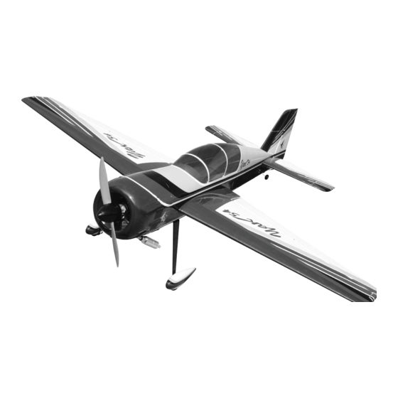
67" YAK 54
LIMITED WARRANTY
© Copyright 2006 Carl Goldberg Products LTD
WARNING
1
TM
Advertisement
Table of Contents

Related Manuals for Carl Goldberg Products YAK 54


Summary of Contents for Carl Goldberg Products YAK 54
- Page 1 LIMITED WARRANTY Carl Goldberg Products has inspected and certified the components of this aircraft. The company urges the buyer to perform his own inspection, prior to assembly, and to immediately request a replacement of any parts he believes to be defective for their intended use.
- Page 2 Building supplies needed 67”Yak 54 ARF to be one of the most respon- sive, in-the-grove aircraft on the market. Just Hobby knife w/#11 blades remember to use common sense when flying Thin CA this high performance machine.
- Page 3 #866 True Red #870 White COVERING The 67”Yak 54 ARF is covered in a premium polyester film chosen by many of the world's top flyers for its beau- ty, toughness, and ease of application and repair. It is not uncommon for ARF's to develop a few wrinkles in transit.
-
Page 4: Wing Assembly
WING ASSEMBLY With the aileron servo in place, make a mark CONTROL HORN PART NAMES on the aileron at a 90º degree angle to the trailing edge and in line with the servo. Look swing in keepers for the control horn hard point under the cov- ering. -
Page 5: Aileron Servo Installation
AILERON INSTALLATION Select the aileron for the wing half on which you are working. Mix up a liberal amount of 30 minute epoxy. Using a piece of wire or a toothpick, work some epoxy into each hole on the wing and aileron. Working with 1 hinge at a time, place a dab of Collect the following parts: epoxy and insert the hinge half way into one of... - Page 6 1/16” Attach the 12” servo extension to the servo. IMPO RTANT! To ensure that any connections locat- ed inside the wing will not come loose, either when the wires are pulled, or during flying, always tape them securely together with electrical tape. Slide the silicone keeper on the clevis Screw the 2-56 pushrod into the clevis so 1/16”...
- Page 7 3/8” Bend the pushrod 90 degrees at the location of your mark. Cut the remaining wire leaving 3/8”. Install the nylon swing in keeper to attach the pushrod. Repeat for the other aileron.
- Page 8 FUSELAGE HATCH I nsert the gear legs through the slots in the fuselage side. The top front half of the fuselage is a hatch. Remove Use the six 6-32 x 1” bolts to secure the gear. the 4-40 socket head bolts on the side of the fuse- The blind nuts are already installed in the lage to disengage the hatch.
- Page 9 Install the blind nut in the wheel pant using the HINGING RUDDER 4-40 bolt to pull it into the hole. Landing Gear Wheel Pant Wheel Collars Wheel Mount the wheel pant on the landing gear along with the wheel collars and wheels. Center the wheel on the axle.
- Page 10 Use the four #2 x 1/2” screws to mount the tail wheel bracket to the bottom of the fuselage. Draw a line across the hinge line of the rudder and transfer the mark to the other side of the rudder. Using a 1\8”...
- Page 11 HINT: Drill the hole from the bottom half way. Then measure and mark the top of the Slide the stab onto the aluminum tubes. aileron and drill down to the hole from the Use the two #4x 1/2” screws to lock the stab top of the aileron.
-
Page 12: Elevator Servos
ELEVATOR SERVOS Collect the following items (2) Servos (2) 2-56 x 32” pushrods (2) 2-56 clevis (2) silicone clevis keepers (2) nylon swing in keepers Install the servos in the servo tray as shown. Locate the hole in the fuselage side and install the 2-56 pushrod into the pushrod tube already installed in the fuselage. -
Page 13: Rudder Servo Installation
Repeat for the other elevator servo. Rudder Servo Installation Collect the following parts: You can bend the pushrod in the plane Make the 90 degree bend and then cut the remain- (2) 2-56 clevis ing wire off leaving a 3/8” length. (2) silicon clevis keepers (2) rigging couplers With the pushrod reinstall, attach to the servo... - Page 14 Install the rudder servo in the center slot of servo tray. Pull the cable tight and crimp the swage with a pair of pliers. You will need a heavy duty double sided con- trol arm. Tape the rudder in the neutral position. Make sure the rudder servo is centered.
-
Page 15: Engine Installation
ENGINE INSTALLATION The Motor you choose may have a different type installation as show. We show an O.S. 1.20 motor, this motor has more than enough power to make this plane perform to its limits. If you choose this powerful motor then you must make sure that you go over all high stress joints with white glue or a epoxy. -
Page 16: Cowl Mounting
Mark the location of the mounting holes on the Mount the engine using the four 3mm x 25mm mounts. Remove the engine and drill a 1/8” screws and flat washers. hole at each location. Be sure and use thread lock on the bolts. Mount the engine to the mounts using the four 3mm x 20mm self tapping screws. - Page 17 To locate the needle valve outlet hole, tape a piece of paper to the side of the fuselage with the needle valve extension through the paper. Mount the cowl in position and hold in place using masking tape. You will have to make a cut out for the engine head on the bottom of the cowl.
-
Page 18: Throttle Servo Installation
Mount the throttle servo on either the left or right side of the plane depending on the engine you use. Mount the servo so it will be on the same side of the plane as your throttle arm on the Reinstall the cowl and transfer the hole loca- engine. -
Page 19: Fuel Tank Installation
Fuel Tank Installation Collect the following items: (1) fuel tank (1) cap assembly (1) clunk (1) pick up tube (3) aluminum tubes Attach the ez-connector to your servo arm. Put a drop of CA on the nut to make sure it does not come loose. - Page 20 Attach the fuel pickup line to one of the straight tubes. The two rails can be glued the the fuselage sides and the tank tray glued to the rails. This Attach the clunk to the other end. shows the tank mount in the forward position. Fit assembly into the tank and adjust the length of the pickup line so the clunk is about 1/4”...
-
Page 21: Canopy Mounting
Receiver and Switch Installation Canopy Mounting. The switch can be mounted in any convenient location. The sheeted part of the fuselage just below the sides work really well. Do not glue the canopy to the hatch without the hatch mounted to the fuselage. You can warp it and it will not fit back on the fuselage. - Page 22 wing bolt Final Assembly Attach cowl using locktite on the screws. Install muffler, needle valve, prop and spinner. Control Throws and CG Ailerons Low Rate 3/4” each direction High Rate 1-1/2” each direction Elevators Low Rate 1-1/4” each direction High Rate 3”...
Need help?
Do you have a question about the YAK 54 and is the answer not in the manual?
Questions and answers