Table of Contents
Advertisement
Quick Links
Advertisement
Table of Contents

Related Manuals for Supero SuperServer 5014C-MR


Summary of Contents for Supero SuperServer 5014C-MR
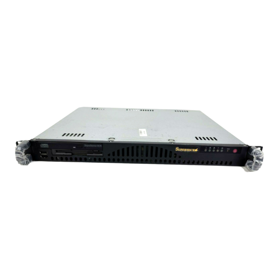
- Page 1 UPER ® 5014C-MR UPER ERVER USER’S MANUAL Revision 1.0a...
- Page 2 Clara County in the State of California, USA. The State of California, County of Santa Clara shall be the exclusive venue for the resolution of any such disputes. Supermicro's total liability for all claims will not exceed the price paid for the hardware product.
-
Page 3: About This Manual
About This Manual This manual is written for professional system integrators and PC technicians. It provides information for the installation and use of the SuperServer 5014C-MR. Installation and maintainance should be performed by experienced technicians only. The SuperServer 5014C-MR is a high-end single processor mini 1U rackmount server based on the SC512C-260 1U rackmount server chassis and the Super P8SCT motherboard. - Page 4 UPER ERVER 5014C-MR User's Manual Chapter 4: System Safety You should thoroughly familiarize yourself with this chapter for a general overview of safety precautions that should be followed when installing and servicing the SuperServer 5014C-MR. Chapter 5: Advanced Motherboard Setup Chapter 5 provides detailed information on the P8SCi motherboard, including the locations and functions of connectors, headers and jumpers.
- Page 5 Preface Notes...
-
Page 6: Table Of Contents
UPER ERVER 5014C-MR User's Manual Table of Contents Preface About This Manual ... iii Manual Organization ... iii Chapter 1: Introduction Overview ... 1-1 Motherboard Features ... 1-2 Server Chassis Features ... 1-5 Contacting Supermicro ... 1-6 Chapter 2: Server Installation Overview ... - Page 7 NIC1 ... 3-2 HDD ... 3-2 Power ... 3-3 Chapter 4: System Safety Electrical Safety Precautions ... 4-1 General Safety Precautions ... 4-2 ESD Precautions ... 4-3 Operating Precautions ... 4-4 Chapter 5: Advanced Motherboard Setup Handling the Motherboard ... 5-1 Motherboard Installation ...
- Page 8 UPER ERVER 5014C-MR User's Manual Universal Serial Bus ... 5-15 Wake-On-LAN ... 5-16 Wake-On-Ring ... 5-16 SMB Header ... 5-16 GLAN1/2 (Ethernet Ports) ... 5-16 5-10 Jumper Settings ... 5-17 Explanation of Jumpers ... 5-17 CMOS Clear ... 5-17 USB Wake-Up ... 5-18 Watch Dog Enable/Disable ...
- Page 9 7-4.2 Advanced Chipset Control ... 7-7 7-4.3 I/O Device Confi guration ... 7-9 7-4.4 PnP Confi guration ... 7-10 7-4.5 Hardware Monitors ... 7-12 7-4.6 Processor and Clock Options ... 7-14 7-4.7 DMI Event Log ... 7-15 7-4.8 Console Redirection ... 7-16 Security ...
- Page 10 UPER ERVER 5014C-MR User's Manual Notes...
-
Page 11: Chapter 1: Introduction
533 MHz front side bus in an LGA775 type socket and up to 4 GB of DDR2-533/400 SDRAM memory. Please refer to our web site for information on operating systems that have been certifi ed for use with the 5014C-MR (www. supermicro.com) and for regular updates on supported processor speeds. -
Page 12: Motherboard Features
ERVER 5014C-MR User's Manual Motherboard Features At the heart of the SuperServer 5014C-MR lies the P8SCi, a single processor moth- erboard designed to provide maximum performance. Below are the main features of the P8SCi. (See Figure 1-1 for a block diagram of the E7221 chipset.) -
Page 13: Onboard Controllers/Ports
Onboard Controllers/Ports An onboard IDE controller supports one fl oppy drive and up to four Ultra ATA 100 hard drives or ATAPI devices. Onboard I/O backpanel ports include one serial COM port, one parallel port, two USB ports, a VGA (monitor) port, PS/2 mouse and keyboard ports and two GLAN (RJ45) ports. - Page 14 UPER ERVER 5014C-MR User's Manual Figure 1-1 . Intel E7221 Chipset: System Block Diagram Note: This is a general block diagram. Please see Chapter 5 for details. Figure 1-2. Rear I/O Panel Parallel Port Keyboard/ Mouse Ports USB Ports COM1 Port...
-
Page 15: Server Chassis Features
Server Chassis Features The SuperServer 5014C-MR is a mini 1U rackmount server platform confi gura- tion. The following is a general outline of the main features of the SC512C-260 chassis. System Power When confi gured as a SuperServer 5014C-MR, the SC512C-260 chassis includes a single 260W power supply. -
Page 16: Contacting Supermicro
UPER ERVER 5014C-MR User's Manual Contacting Supermicro Headquarters Address: SuperMicro Computer, Inc. 980 Rock Ave. San Jose, CA 95131 U.S.A. Tel: +1 (408) 503-8000 Fax: +1 (408) 503-8008 Email: marketing@supermicro.com (General Information) support@supermicro.com (Technical Support) Web Site: www.supermicro.com Europe Address: SuperMicro Computer B.V. -
Page 17: Chapter 2: Server Installation
This quick setup assumes that your 5014C-MR system has come to you with the processor and memory prein- stalled. If your system is not already fully integrated with a motherboard, processor, system memory etc., please turn to the chapter or section noted in each step for... -
Page 18: Choosing A Setup Location
UPER ERVER 5014C-MR User's Manual Choosing a Setup Location - Leave enough clearance in front of the rack to enable you to open the front door completely (~25 inches). - Leave approximately 30 inches of clearance in the back of the rack to allow for suffi... -
Page 19: Rack Mounting Considerations
Chapter 2: Server Installation Rack Mounting Considerations Ambient Operating Temperature If installed in a closed or multi-unit rack assembly, the ambient operating tempera- ture of the rack environment may be greater than the ambient temperature of the room. Therefore, consideration should be given to installing the equipment in an environment compatible with the manufacturer’s maximum rated ambient tempera- ture (Tmra). -
Page 20: Identifying The Sections Of The Rack Rails
Sections 2-5 and 2-6. Basic Installation Procedure The 5014C-MR server comes with two rack mounting brackets, which are located on each side at the front of the chassis. To mount the system into a rack, simply screw these brackets directly to the front of the rack (two screws for each bracket). -
Page 21: Installing The Chassis Rails
Figure 2-2. Installing Chassis Rails Installing the Rack Rails Determine where you want to place the 5014C-MR in the rack (see Rack and Server Precautions in Section 2-3). Position the fi xed rack rail/sliding rail guide assemblies at the desired location in the rack, keeping the sliding rail guide facing the inside of the rack. -
Page 22: Installing The Server Into The Rack
UPER ERVER 5014C-MR User's Manual Installing the Server into the Rack You should now have rails attached to both the chassis and the rack unit. The next step is to install the server into the rack. Do this by lining up the rear of the chas- sis rails with the front of the rack rails. -
Page 23: Installing The Server Into A Telco Rack
Figure 2-4. Installing the Server into a Rack: w/ Rackmount Kit Installing the Server into a Telco Rack If you are installing the SuperServer 5014C-MR into a Telco type rack, follow the di- rections given on the previous pages for rack installation. The only difference in the installation procedure will be the positioning of the rack brackets to the rack. -
Page 24: Checking The Motherboard Setup
Figure 2-5. Installing the Server into a Telco Rack: Basic Checking the Motherboard Setup After you install the 5014C-MR in the rack, you will need to open the unit to make sure the motherboard is properly installed and all the connections have been made. - Page 25 3. Check the system memory Your 5014C-MR server system may have come with system memory already installed. Make sure all DIMMs are fully seated in their slots. For details on adding system memory, refer to Chapter 5.
- Page 26 The air seals are located under the blower fan and beneath the frame cross section that separates the drive bay area from the motherboard area of the chassis. Note: Make sure that the air seals are properly installed. Figure 2-7. Accessing the Inside of the SuperServer 5014C-MR 2-10...
-
Page 27: Checking The Drive Bay Setup
Chapter 2: Server Installation Checking the Drive Bay Setup Next, you should check to make sure the peripheral drives and the Serial ATA drive have been properly installed and all essential connections have been made. 1. Accessing the drive bays For servicing the Serial ATA, CD-ROM and fl... - Page 28 UPER ERVER 5014C-MR User's Manual Notes 2-12...
-
Page 29: Chapter 3: System Interface
System Interface Overview There are several LEDs on the control panel to keep you constantly informed of the overall status of the system as well as the activity and health of specifi c com- ponents. There are also two buttons on the chassis control panel. This chapter explains the meanings of all LED indicators and the appropriate response you may need to take. -
Page 30: Control Panel Leds
UPER ERVER 5014C-MR User's Manual Control Panel LEDs The control panel located on the front of the SC512C-260 chassis has fi ve LEDs. These LEDs provide you with critical information related to different parts of the system. This section explains what each LED indicates when illuminated and any corrective action you may need to take. -
Page 31: Power
Chapter 3: System Interface Power: Indicates power is being supplied to the system's power supply units. This LED should normally be illuminated when the system is operating. - Page 32 UPER ERVER 5014C-MR User's Manual Notes...
-
Page 33: Chapter 4: System Safety
Electrical Safety Precautions Basic electrical safety precautions should be followed to protect yourself from harm and the SuperServer 5014C-MR from damage: Be aware of the locations of the power on/off switch on the chassis as well as the room's emergency power-off switch, disconnection switch or electrical outlet. -
Page 34: General Safety Precautions
General Safety Precautions Follow these rules to ensure general safety: Keep the area around the SuperServer 5014C-MR clean and free of clutter. The SuperServer 5014C-MR weighs approximately 23 lbs (~10.5 kg) when fully loaded. When lifting the system, two people at either end should lift slowly with their feet spread out to distribute the weight. -
Page 35: Esd Precautions
ESD Precautions Electrostatic discharge (ESD) is generated by two objects with different electrical charges coming into contact with each other. An electrical discharge is created to neutralize this difference, which can damage electronic com ponents and printed circuit boards. The following measures are generally suffi cient to neutralize this difference before contact is made to protect your equipment from ESD: Use a grounded wrist strap designed to prevent static discharge. -
Page 36: Operating Precautions
Operating Precautions Care must be taken to assure that the chassis cover is in place when the 5014C-MR is operating to assure proper cooling. Out of warranty damage to the 5014C-MR system can occur if this practice is not strictly followed. -
Page 37: Chapter 5: Advanced Motherboard Setup
Advanced Motherboard Setup This chapter covers the steps required to install processors and heatsinks to the P8SCi motherboard, connect the data and power cables and install add-on cards. All motherboard jumpers and connections are also described and a layout and quick reference chart are included in this chapter. -
Page 38: Motherboard Installation
The P8SCi requires a chassis big enough to support a 12" x 9.5" motherboard, such as Supermicro's SC512C 1U rackmount. Make sure that the I/O ports on the motherboard align properly with their respective holes in the I/O shield at the back of the chassis. -
Page 39: Connecting Cables
Connecting Cables Now that the motherboard is installed, the next step is to connect the cables to the board. These include the data (ribbon) cables for the peripherals and control panel and the power cables. Connecting Data Cables The ribbon cables used to transfer data from the peripheral devices have been care- fully routed to prevent them from blocking the fl... -
Page 40: I/O Ports
UPER ERVER 5014C-MR User's Manual Figure 5-1. Control Panel Header Pins Power LED HDD LED OH/Fan Fail LED I/O Ports The I/O ports are color coded in conformance with the PC 99 specifi cation. See Figure 5-2 below for the colors and locations of the various I/O ports. -
Page 41: Installing Processors
Installing Processors Avoid placing direct pressure to the top of the processor package. Always remove the power cord fi rst before adding, removing or changing any hardware components. Processor Support The P8SCi has a single LGA775 socket, which supports Intel Pentium 4 and Intel Celeron processors. - Page 42 UPER ERVER 5014C-MR User's Manual 4. Use your thumb and index fi nger to hold the CPU at the north center and south center edges of the CPU. 5. Align Pin 1 of the CPU with Pin 1 of the socket. Once aligned, carefully lower the CPU straight down and into the socket.
-
Page 43: Heat Sink Installation
Chapter 5: Advanced Motherboard Setup Heatsink Installation 1. Do not apply any thermal grease to the heatsink or the CPU die; the required amount has already been applied. 2. Place the heatsink on top of the CPU so that the four mounting holes are aligned with those on the retention mechanism. -
Page 44: Installing Memory
UPER ERVER 5014C-MR User's Manual Installing Memory CAUTION! Exercise extreme care when installing or removing DIMM modules to prevent any possible damage. 1. Memory support The P8SCi supports up to 4 GB of DDR2-533/400 unbuffered ECC SDRAM. The P8SCi employs a dual-channel memory confi guration, meaning DIMM sockets must be populated in pairs with the same size/same type of memory modules. -
Page 45: Adding Pci Cards
Adding PCI Cards 1. 64-bit PCI-X slot The 5014C-MR has a riser card (p/n CSE-RR1U-X) designed specifi cally for use in the SC512C-260 1U rackmount chassis (included with the system). This riser card allows an installed PCI-X card to sit at a 90 degree angle so it can fi t inside the chassis. -
Page 46: P8Sci Layout
UPER ERVER 5014C-MR User's Manual Motherboard Details JPWAKE1 Keyboard/ ATX Power Connector Mouse USB0/1 COM1 JPUSB1 North Bridge GLAN1 GLAN2 BANK1 BANK2 GLAN Controller GLAN Controller ICH6R South Bridge JPL1 JPL2 33 MHz PCI PCI-Exp 1x PCI-Exp 1x JWOR SATA3... -
Page 47: P8Sci Quick Reference
P8SCi Quick Reference Jumpers Description Speaker Setting JBT1 CMOS Clear Power Force On JPL1/PL2 GLAN1/2 JPUSB1 USB1/2 Wake Up JPWAKE1 Keyboard Wake-up Watch Dog Reset/NMI Connector Description COM1/COM2 COM Port 1 Connector /COM Port2 Header Fan1-5 Fan Headers Floppy Floppy Disk Drive Connector IDE Port IPMI IPMI Connector... -
Page 48: Connector Defi Nitions
UPER ERVER 5014C-MR User's Manual Connector Defi nitions Power Supply Connectors The primary power supply connector on the P8SCi meets the SSI (Superset ATX) 24-pin specifi cation. Refer to the table on the right for the pin defi nitions of the ATX 24-pin power connector (J1). -
Page 49: Power Button Connector
Power Button Connector The power button connector is lo- cated on pins 1 and 2 of JF1. This header should be connected to the chassis power button, which you may also confi gure to put the system into suspend mode (see the Power Button Mode setting in BIOS). -
Page 50: Hdd Led
UPER ERVER 5014C-MR User's Manual HDD LED The IDE/SATA LED is located on pins 13 and 14 of JF1. This LED is used to display all IDE and SATA activity on all drives. See the table on the right for pin defi nitions. -
Page 51: Chassis Intrusion
Chassis Intrusion The Chassis Intrusion header is desig- nated JL1 and located near the FAN4 header. See the table on the right for pin defi nitions. ATX PS/2 Keyboard and PS/2 Mouse Ports The ATX PS/2 keyboard and the PS/2 mouse ports are designated J14. -
Page 52: Wake-On-Lan
UPER ERVER 5014C-MR User's Manual Wake-On-LAN The Wake-On-LAN header is des- ignated JWOL on the motherboard. See the table on the right for pin defi ni- tions. You must enable the appropri- ate WOL setting in BIOS to use this function. -
Page 53: 5-10 Jumper Settings
5-10 Jumper Settings Explanation of Jumpers To modify the operation of the mother- board, jumpers can be used to choose between optional settings. Jumpers create shorts between two pins to change the function of the connector. Pin 1 is identifi ed with a square solder pad on the printed circuit board. -
Page 54: Usb Wake-Up
UPER ERVER 5014C-MR User's Manual USB Wake-Up Use JPUSB1 to enable or disable USB Wake-Up, which allows you to wake up the system by depressing a key on the keyboard or by clicking the mouse when either is connected to the USB0 or USB1 port. Enable... -
Page 55: Keyboard Wake-Up
Keyboard Wake-Up The JPWAKE1 jumper (and the cor- responding BIOS setting) is used to allow the system to be woken up by depressing a key on the keyboard from an S1 or S3 state in Windows OS. See the table on the right for jumper settings. -
Page 56: 5-11 Onboard Indicators
UPER ERVER 5014C-MR User's Manual 5-11 Onboard Indicators GLAN LEDs The Ethernet ports (located beside the VGA port) have two LEDs. On each Gb LAN port, the yellow (right) LED indicates activity while the left LED may be green, orange or off to indicate the speed of the connection. -
Page 57: Parallel Port
Parallel Port Connector The parallel port is located on J11. See the table on the right for pin defi nitions. Floppy Connector The fl oppy connector is designated "Floppy". See the table on the right for pin defi nitions. Chapter 5: Advanced Motherboard Setup Parallel (Printer) Port Connector Pin Defi... -
Page 58: Ide Connector
UPER ERVER 5014C-MR User's Manual IDE Connector There are no jumpers to confi gure the onboard IDE interface, which is designated "IDE". See the table below for pin defi nitions. Pin# IDE Drive Connectors Pin Defi nitions (IDE) Defi nition Pin # Defi... -
Page 59: Chapter 6: Advanced Chassis Setup
Advanced Chassis Setup This chapter covers the steps required to install components and perform mainte- nance on the SC512C-260 chassis. For component installation, follow the steps in the order given to eliminate the most common problems encountered. If some steps are unnecessary, skip ahead to the step that follows. Tools Required The only tool you will need to install components and perform maintainance is a Philips screwdriver. -
Page 60: Control Panel
UPER ERVER 5014C-MR User's Manual Figure 6-1. Chassis Front View Figure 6-2. Chassis Rear View Parallel Port Keyboard/ Mouse Ports USB Ports COM1 Port Control Panel The control panel (located on the front of the chassis) must be connected to the JF1 connector on the motherboard to provide you with system control buttons and status indicators. -
Page 61: System Fans
Chapter 6: Advanced Chassis Setup System Fans One 100-mm blower fan provides the cooling for the SuperServer 5014C-MR. The chassis includes air seals under the blower fans and at the chassis cross section, which separates the drive bay area from the motherboard area of the chassis to promote better airfl... -
Page 62: Drive Bay Installation/Removal
Serial ATA or fl oppy disk drive, you will need to gain access to the inside of the 5014C-MR by removing the top cover of the chassis. Note: Only a "slim" CD-ROM and a "slim" fl oppy drive will fi t in the 5014C-MR. Serial ATA Drive Installation The SATA drive is located at the front of the chassis, making it easily accessible for installation and removal. -
Page 63: Cd-Rom And Floppy Drive Installation
fl oppy drive bays. Both the CD-ROM and the fl oppy drives must have a "slim" profi le to fi t into the 5014C-MR. If you cannot remove the top cover with the system remaining in the rack, follow the procedure below. -
Page 64: Power Supply
ERVER 5014C-MR User's Manual Power Supply The SuperServer 5014C-MR has a single 260 watt power supply. This power supply has the capability of operating at 100 - 240 input volts. Power down the system and then unplug the AC power cord to completely remove power from the system before removing the power supply. -
Page 65: Chapter 7: Bios
Often a text message will ac- company it. (Note: BIOS has default text messages built in. Supermicro retains the option to include, omit, or change any of these text messages.) Options printed in Bold are the default settings. -
Page 66: Running Setup
UPER ERVER 5014C-MR User's Manual Running Setup *Optimal default settings are in bold text unless otherwise noted. The BIOS setup options described in this section are selected by choosing the ap- propriate text from the Main BIOS Setup screen. All displayed text is described in this section, although the screen display is often all you need to understand how to set the options (see on next page). -
Page 67: Swap Floppy Drive
Chapter 7: BIOS Date/Time Set the system date and time. Key in the correct information in the "mm", "dd" and "yy" fi elds. Press the "Enter" key to save the data. Legacy Diskette A/Legacy Diskette B This setting allows the user to set the type of fl oppy disk drive installed as diskette A and diskette B. -
Page 68: Ide Hdd Auto Detection
UPER ERVER 5014C-MR User's Manual IDE HDD Auto-Detection This option allows the user to determine the manner in which the AwardBIOS sets the settings for IDE Channel 0 to IDE Channel 3 Master Devices. The options are "None", "Auto" and "Manual."... -
Page 69: Advanced Bios Setup
Chapter 7: BIOS Advanced BIOS Setup Choose the Advanced BIOS Setup from the Award BIOS main menu with the Left/Right arrow keys. You should see the following display. Select one of the items in the left frame of the screen to go to the sub screen for that item. The Advanced BIOS Setup options are displayed by highlighting the option using the arrow keys. - Page 70 UPER ERVER 5014C-MR User's Manual Quick Boot If enabled, this feature allows the system to skip certain tests while booting. This will decrease the time needed to boot the system. The settings are "Enabled" and "Disabled". Quiet Boot This feature allows the user to enable "Quiet Boot". When set to Enabled, the BIOS is in the graphic mode and displays only an OEM Logo during POST while booting.
-
Page 71: 7-4.2 Advanced Chipset Control
Chapter 7: BIOS 7-4.2 Advanced Chipset Control DRAM Data Integrity Mode If enabled, this feature allows the data stored in the DRMA memory to be integrated for faster data processing. The options are ECC and Non-ECC. On-Chip Frame Buffer Size This setting allows you to set On-Chip Frame Buffer Size. -
Page 72: Pata Ide Mode
UPER ERVER 5014C-MR User's Manual PATA IDE Mode When the item -On-chip Serial ATA is set to Combined Mode, the user can select either Primary or Secondary for Parallel ATA IDE. The options are Primary and Secondary. If On-chip Serial ATA is set to Enhanced Mode, only Serial ATA will be activated, and Primary PATA IDE will be available. -
Page 73: 7-4.3 I/O Device Confi Guration
Chapter 7: BIOS 7-4.3 I/O Device Confi guration Onboard Serial Port1/Onboard Serial Port2 This setting allows the user to set the address and the corresponding IRQ for Serial Port1 and Serial Port 2. The options are "Disabled" , "3F8/IRQ4", "2F8/IRQ3", "3E8/ IRQ4", "2E8/IRQ3"... -
Page 74: 7-4.4 Pnp Confi Guration
UPER ERVER 5014C-MR User's Manual Use IR Pins This item sets the usage of the IR pins. The options are "RxD2, TxD2" and "IR- Rx2Tx2". Onboard Parallel Port This setting allows the user to set the address and the corresponding IRQ for the onboard parallel port. -
Page 75: Reset Configuration Data
Chapter 7: BIOS Initial Display From This feature sets the device that will initiate the monitor display when the system is fi rst turned on. The options are "PCI Slot" and "PCI Ex(press)". Reset Confi guration Data Enabling this setting resets the extended system confi guration data when you exit setup. -
Page 76: 7-4.5 Hardware Monitors
UPER ERVER 5014C-MR User's Manual Onboard LAN Boot ROM This feature allows the user to determine if the Boot ROMs of the Onboard LAN chips should be activated. If activated, the user can boot the system from the Onboard LAN chips. The options are Disabled, LAN1, LAN2 and Both. -
Page 77: Cpu Warning Temperature
CPU Warning Temperature This allows you to set the CPU warning temperature. If the CPU temperature reaches this threshold, an alarm will activate and a warning message will be displayed onscreen. The options are "Disabled", "60 "75 C/167 F", "80 C/176 F"... -
Page 78: 7-4.6 Processor And Clock Options
UPER ERVER 5014C-MR User's Manual 7-4.6 Processor & Clock Options Thermal Management This setting determines the method used by the BIOS to control the thermal management of the system. The options are "Thermal Monitor 1 (On die throttling) " and "Thermal Monitor 2 (Ratio & VID transition)." (See Section 1-4 for details.) Limit CPUID MaxVal Select "Enabled"... -
Page 79: 7-4.7 Dmi Event Log
Chapter 7: BIOS 7-4.7 DMI Event Log DMI Event Log This setting allows you to Enable or Disable the function of DMI Event Logging. The options are Disabled and Enabled. Clear All DMI Event Logs Select Yes and press <Enter> to clear all DMI event logs. The default setting is "No."... -
Page 80: 7-4.8 Console Redirection
UPER ERVER 5014C-MR User's Manual 7-4.8 Console Redirection Console Redirection This setting allows you to Enable or Disable the function of Console Redirection. The options are Disabled and Enabled. BAUD Rate Select the BAUD rate for console redirection. The options are 300, 1200, 2400, 9600, 19.2K, 38.4K, 57.6K and 115.2K. -
Page 81: Security
Chapter 7: BIOS Security Choose Security from the Award BIOS main menu with the Left/Right arrow keys. You should see the following display: Set Supervisor Password When the item "Set Supervisor Password" is highlighted on the above screen, press the <Enter> key. When prompted, type the Supervisor Password in the dialogue box to set or to change the Supervisor Password. -
Page 82: Boot
UPER ERVER 5014C-MR User's Manual Boot Choose Boot from the Award BIOS main menu with the Left/Right arrow keys. You should see the following display: The Award BIOS attempts to load the operating system from devices specifi ed by the users in a user-specifi ed sequence. -
Page 83: Boot Other Device
Chapter 7: BIOS Boot Other Device If enabled, this option enables the BIOS to load the OS from another device rather than the ones that have been specifi ed as the fi rst, second and third boot up devices. The settings are "Enabled" and "Disabled". 7-19... -
Page 84: Exit
UPER ERVER 5014C-MR User's Manual Exit Choose Exit from the Award BIOS main menu with the Left/Right arrow keys. You should see the following display: Save & Exit Setup When the item "Save & Exit Setup" is highlighted, press <Enter> to save the changes you've made in the BIOS program (CMOS) and exit. -
Page 85: Appendix A: Bios Post Messages
Appendix A BIOS POST Messages During the Power-On Self-Test (POST), the BIOS will check for problems. If a prob- lem is found, the BIOS will activate an alarm or display a message. The following is a list of such BIOS messages. Beeps (1 long beep+1 short pause) continuously 1 long beep+2 short beeps... - Page 86 UPER ERVER 5014C-MR User's Manual Notes...
-
Page 87: Appendix B: Bios Post Codes
Award BIOS POST Codes This section lists the POST (Power On Self Testing) Codes for the Award BIOS. POST (hex) Description Test CMOS R/W functionality. Early chipset initialization: - Disable shadow RAM - Disable L2 cache (socket 7 or below) - Program basic chipset registers Detect memory - Auto detection of DRAM size, type and ECC. - Page 88 POST (hex) Description Reserved Use walking 1's algorithm to check out interface in CMOS circuitry. Also set real-time clock power status, and then check for override. Reserved Program cipset defaults into chipset. Chipset default values are MODBINable by OEM customers. Reserved Initial Early_Init_Onboard_Generator switch.
- Page 89 POST (hex) Description Reserved Reserved Reserved 1. Initialize multi-language. 2. Put information on screen display, including Award title, CPU type, CPU speed, etc. Reserved Reserved Reserved Reserved Reserved Reset keyboard except Winbond 977 series Super I/O chips. Reserved Reserved Reserved Reserved Reserved Reserved...
- Page 90 POST (hex) Description Reserved Reserved 1. Program MTRR of M1 CPU. 2. Initialize L2 cache for P6 class CPU & program CPU with proper cacheable range. 3. Initialize the APIC for P6 class CPU. 4. On MP platform, adjust the cacheable range to smaller one in case the cache- able ranges between each CPU are not identical.
- Page 91 POST (hex) Description Reserved Reserved (Optional feature) Enter AWDFLASH.EXE if: - AWDFLASH is found in fl oppy drive. - ALT+F2 is pressed Reserved Detect and install all IDE devices: HDD, LS120, ZIP, CD-ROM, etc. Reserved Detect serial ports and parallel ports. Reserved Reserved Detect and install co-processor.
- Page 92 POST (hex) Description Read HDD boot sector information for Trend Anti-Virus. 1. Enable L2 cache. 2. Program boot up speed. 3. Chipset fi nal initialization. 4. Power management fi nal initialization. 5. Clear screen and display memory table. 6. Program K6 write allocation. 7.
-
Page 93: Appendix C: Software Installation
After all the hardware has been installed, you must fi rst confi gure Intel's ICH6R SATA RAID before installing the Windows Operating System and other software drivers. The necessary drivers are all included on the Supermicro CDs that came packaged with your motherboard. (If you do not wish to confi gure onboard SATA RAID functions, please go directly to Section C-5 to install the Operating System &... - Page 94 UPER ERVER 5014C-MR User's Manual ATA Operating Modes You can select from the following two modes: Legacy mode and Native mode. SATA Operating Modes You can select from the following modes: Auto, Combined, Enhanced and SATA Only Mode. The number of devices supported by these modes are listed below:...
- Page 95 Appendix C: Software Installation Using the ICH6R SATA RAID Utility Program Creating, Deleting and Reseting RAID Volumes 1. After the system exits the BIOS Setup Utility, the system will automatically reboot. The following screen appears after the Power-On Self Test. 2.
- Page 96 UPER ERVER 5014C-MR User's Manual 2. Specify the RAID volume name and press the <Tab> key or the <Enter> key to go to the next fi eld. (Use the <Esc> key to return to the previous menu.) 3.Use the<Tab>, <Up Arrow>, <Down Arrow> and <Enter> keys to enter the ap- propriate values for the items selected and go to the next fi...
-
Page 97: Appendix C: Software Installation
Appendix C: Software Installation 5. You will return to the main menu with DISK/VOLUME INFORMATION updated as shown in the following screen. 6. Once the above screen appears, use the <Down Arrow> key to select "Exit" and press the <Enter> key. The following screen will appear:... -
Page 98: Deleting A Raid Volume
UPER ERVER 5014C-MR User's Manual 7. When asked "Are you sure you want to exit? (Y/N):", type "Y" to confi rm the selections and exit the "Create RAID Volume" menu. Press the <Enter> key to return to the main menu. -
Page 99: Reset Disks To Non-Raid
Appendix C: Software Installation 3. When asked "Are you sure you want to delete this volume?", type "Y" to confi rm and press the <Enter> key to return to the main menu. (Use the <Esc> key to return to the previous menu.) Reset Disks to Non-RAID 1. - Page 100 UPER ERVER 5014C-MR User's Manual 2. When asked "Are you sure you want to reset all RAID data (Y/N):", type "Y" to confi rm the selection, and press the <Enter> key to return to the main menu. Exiting the ICH6R SATA RAID Confi guration Utility Program 1.
- Page 101 The necessary drivers are all included on the Supermicro CDs that came packaged with your motherboard. Insert the Supermicro CD that came with the package into the CD-ROM drive, and the following screen will appear: Click the icons showing a hand writing on paper to view the readme fi les for each item.
-
Page 102: Supero Doctor
UPER ERVER 5014C-MR User's Manual Supero Doctor III The Supero Doctor III program is a web-based management tool that supports remote management capabilities with both remote and local management tools. The local management tool is called the Supero Doctor III Client. Supero Doctor III (which is included on the CD-ROM that came with your motherboard) allows you to monitor the environment and operations of your system. - Page 103 Supero Doctor III Interface (Remote Control Screen) Supero Doctor III revision 1.0 can be downloaded from our website at ftp://ftp. supermicro.com/utility/Supero_Doctor_III/. You can also download the SDIII User's Guide at: http://www.supermicro.com/PRODUCT/Manuals/SDIII/UserGuide. pdf. For Linux, we recommend using Supero Doctor II.
- Page 104 UPER ERVER 5014C-MR User's Manual Notes C-12...
-
Page 105: Appendix D: System Specifi Cations
Appendix D: System Specifi cations Appendix D System Specifi cations Processors Single Intel® Pentium® LGA775 processors at a front side (system) bus speed of 800 MHz or single Intel® Celeron® processors at a front side bus speed of 533 MHz Note: Please refer to our web site for a complete listing of supported processors. - Page 106 UPER ERVER 5014C-MR User's Manual Expansion Slots (provided with included riser card) One (1) riser card to support the use of one full size, half-length 64-bit PCI-X expansion card Motherboard Model: P8SCi (Extended ATX form factor) Dimensions: 12 x 9.5 in (305 x 241 mm)
-
Page 107: Regulatory Compliance
Appendix D: System Specifi cations Regulatory Compliance Electromagnetic Emissions: FCC Class B, EN 55022 Class B, EN 61000-3-2/-3-3, CISPR 22 Class B Electromagnetic Immunity: EN 55024/CISPR 24, (EN 61000-4-2, EN 61000-4-3, EN 61000-4-4, EN 61000-4-5, EN 61000-4-6, EN 61000-4-8, EN 61000-4-11) Safety: EN 60950/IEC 60950-Compliant, UL Listed (USA), CUL Listed (Canada), TUV Certifi... - Page 108 UPER ERVER 5014C-MR User's Manual Notes...
Need help?
Do you have a question about the SuperServer 5014C-MR and is the answer not in the manual?
Questions and answers