Moxa Technologies EtherDevice EDS-G205A-4PoE Hardware Installation Manual
Hide thumbs
Also See for EtherDevice EDS-G205A-4PoE:
- Quick installation manual (14 pages) ,
- Hardware installation manual (13 pages) ,
- Quick installation manual (14 pages)

Related Manuals for Moxa Technologies EtherDevice EDS-G205A-4PoE


Summary of Contents for Moxa Technologies EtherDevice EDS-G205A-4PoE
- Page 1 EDS-G205A-4PoE Hardware Installation Guide Moxa EtherDevice Switch First Edition, October 2011 2011 Moxa Inc. All rights reserved. P/N: 1802002051020...
-
Page 2: Package Checklist
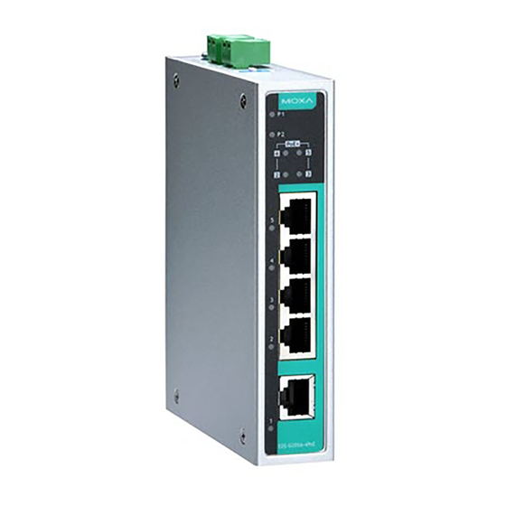
Overview The EDS-G205A-4PoE series industrial Ethernet switches are rugged entry-level industrial 5-port gigabit PoE switches that support IEEE 802.3, IEEE 802.3u, IEEE 802.3x with 10/100/1000M, full/half-duplex, MDI/MDIX auto-sensing, and IEEE 802.3af/IEEE 802.3at PoE standards. The EDS-G205A-4PoE series provides 24/48 VDC redundant power inputs that can be connected simultaneously to a live DC power source. - Page 3 EDS-G205A-4PoE (Standard) Panel Layouts 1. Terminal blocks for P1/P2 power inputs 2. Power input P1 LED 3. Power input P2 LED 4. PoE status LED 5. 10/100/1000Base-T(X) PoE ports (port 2/3/4/5) 6. TP port speed LED 7. 10/100/1000Base-T(X) port (port 1) 8.
-
Page 4: Mounting Dimensions (Unit = Mm)
Mounting Dimensions (unit = mm) DIN-Rail Mounting The aluminum DIN-Rail attachment plate should already be fixed to the back panel of the EDS when you take it out of the box. If you need to reattach the DIN-Rail attachment plate, make sure the stiff metal spring is situated towards the top, as shown in the figures below. -
Page 5: Wall Mounting (Optional)
To remove the EDS from the DIN-Rail, simply reverse Steps 1 and 2 above. Wall Mounting (optional) For some applications, you will find it convenient to mount the EDS-G205A-4PoE on the wall, as shown in the following figures. STEP 1: Remove the aluminum DIN-Rail attachment plate from the EDS-G205A-4PoE’s rear... -
Page 6: Wiring Requirements
Wiring Requirements WARNING Safety First Turn the power off before disconnecting modules or wires. The correct power supply voltage is listed on the product label. Check the voltage of your power source to make sure that you are using the correct voltage. Do NOT use a voltage greater than what is specified on the product label Calculate the maximum possible current in each power wire and common wire. -
Page 7: Communication Connections
STEP 1: Insert the negative/positive DC wires into the V-/V+ terminals. STEP 2: To keep the DC wires from pulling loose, use a small flat-blade screwdriver to tighten the wire-clamp screws on the front of the terminal block connector. STEP 3: Insert the plastic terminal block connector prongs into the terminal block receptor, which is located on EDS’s top panel. - Page 8 1000Base-T Pinouts MDI Port MDI-X Port 8-pin RJ45 Pinouts Pinouts Signal Signal BI_DA+ BI_DB+ BI_DA- BI_DB- BI_DB+ BI_DA+ BI_DC+ BI_DD+ BI_DC- BI_DD- BI_DB- BI_DA- BI_DD+ BI_DC+ BI_DD- BI_DC- PoE Ethernet Port Connection PoE ports located on the EDS switch’s front panel are used to connect to PoE-enabled devices.
-
Page 9: Redundant Power Inputs
RJ45 (8-pin) to RJ45 (8-pin) Cable Wiring NOTE If the PD only supports PoE MDI mode (V+, V+, V-, V- for pins 1, 2, 3, 6), choose a cross-over Ethernet cable to connect the PD and the EDS switch. If the PD only supports PoE MDI-X mode (V-, V-, V+, V+ for pins 1, 2, 3, 6), choose a straight-through Ethernet cable between the PD and the EDS switch. -
Page 10: Led Indicators
DIP Switch Setting Description – – Serves no function (reserved for future use). Enables broadcast storm protection Disables broadcast storm protection ATTENTION To actively update DIP switch settings, power off and then power on the EDS. LED Indicators The front panel of the EDS switches contain several LED indicators. The function of each LED is described in the following table. -
Page 11: Auto Mdi/Mdi-X Connection
Auto MDI/MDI-X Connection The Auto MDI/MDI-X function allows users to connect the EDS’s 10/100/1000Base-T(X) ports to any kind of Ethernet device, without needing to pay attention to the type of Ethernet cable being used for the connection. This means that you can use either a straight-through cable or cross-over cable to connect the EDS to Ethernet devices. -
Page 12: Specifications
Specifications Technology Standards IEEE 802.3 for 10BaseT, IEEE 802.3u for 100BaseT(X) and 100BaseFX, IEEE 802.3ab for 1000Base-T IEEE 802.3z for 1000Base-X IEEE 802.3x for Flow Control IEEE 802.3af for PoE IEEE 802.3at for PoE+ Processing Type Store and Forward Interface RJ45 Ports 10/100/1000Base-T(X) auto negotiation speed, F/H duplex mode, and auto MDI/MDI-X connection... -
Page 13: Technical Support Contact Information
EN61000-4-5 (Surge), Level 3 EN61000-4-6 (CS), Level 3 EN61000-4-8 Shock IEC 60068-2-27 Freefall IEC 60068-2-32 Vibration IEC 60068-2-6 WARRANTY Time Period 5 years Details www.moxa.com/warranty Technical Support Contact Information www.moxa.com/support Moxa Americas: Moxa Europe: Toll-free: 1-888-669-2872 Tel: +49-89-3 70 03 99-0 Tel: +1-714-528-6777 Fax:...
Need help?
Do you have a question about the EtherDevice EDS-G205A-4PoE and is the answer not in the manual?
Questions and answers