Moxa Technologies EDS-505A Installation Manual
Etherdevice
Hide thumbs
Also See for EDS-505A:
- Hardware installation manual (17 pages) ,
- User manual (129 pages) ,
- Manual (84 pages)

Subscribe to Our Youtube Channel
Related Manuals for Moxa Technologies EDS-505A


Summary of Contents for Moxa Technologies EDS-505A
- Page 1 EDS-505A/508A Hardware Installation Guide Moxa EtherDevice™ Switch Ninth Edition, April 2014 2014 Moxa Inc. All rights reserved. P/N: 1802005000018 www.ipc2u.ru www.moxa.pro...
-
Page 2: Package Checklist
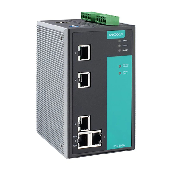
Package Checklist The Moxa EDS-505A/508A is shipped with the following items. If any of these items is missing or damaged, please contact your customer service representative for assistance. • 1 Moxa EtherDevice Switch (EDS-505A or EDS-508A) • Hardware Installation Guide •... - Page 3 Panel Layout of EDS-505A/508A (Standard) 1. Grounding screw 2. Terminal block for power input PWR1/PWR2 and relay output 3. Heat dissipation orifices 4. Console port 5. DIP switches 6. Power input PWR1 LED 7. Power input PWR2 LED 8. Fault LED 9.
- Page 4 Panel Layout of EDS-505A/508A (SC-type) NOTE: The appearance of EDS-505A-SS-SC is identical to that of EDS-505A-MM-SC. The appearance of EDS-508A-SS-SC is identical to that of EDS-508A-MM-SC. 1. Grounding screw 2. Terminal block for power input PWR1/PWR2 and relay output 3. Heat dissipation orifices 4.
- Page 5 Panel Layout of EDS-505A/508A (ST-type) 1. Grounding screw 2. Terminal block for power input PWR1/PWR2 and relay output 3. Heat dissipation orifices 4. Console port 5. DIP switches 6. Power input PWR1 LED 7. Power input PWR2 LED 8. Fault LED 9.
-
Page 6: Mounting Dimensions
Mounting Dimensions Unit = mm (inch) - 6 - www.ipc2u.ru www.moxa.pro... -
Page 7: Din-Rail Mounting
DIN-Rail Mounting The aluminum DIN-Rail attachment plate should already be fixed to the back panel of the EDS-505A/508A when you take it out of the box. STEP 1: STEP 2: Insert the top of the DIN-Rail into The DIN-Rail attachment unit will the slot just below the stiff metal snap into place as shown. -
Page 8: Atex Information
ATEX Information 1. Certificate number DEMKO 08 ATEX 0712961X 2. Ambient range (-40°C ≤ Tamb ≤ 75°C) 3. Certification string (Ex nA nC IIC T4 Gc) 4. Standards covered ( EN60079-0:2012, EN60079-15:2010) 5. The conditions of safe usage: • These products must be mounted in an IP54 enclosure. •... -
Page 9: Wiring The Redundant Power Inputs
The fault circuit will open if: 1. A relay warning event is triggered, OR 2. The EDS-505A/508A is the Master of this Turbo Ring, and the Turbo Ring is broken, OR 3. Start-up failure. If none of these three conditions is met, the fault circuit will remain closed. -
Page 10: Wiring The Digital Inputs
DC power source voltage is stable. Wiring the Digital Inputs The EDS-505A/508A unit has two sets of digital inputs, DI 1 and DI 2. Each DI consists of two contacts of the 6-pin terminal block connector on the EDS’s top panel. The remaining contacts are used for the EDS’s two DC inputs. -
Page 11: 100Basefx Ethernet Port Connection
RJ45 (8-pin) to RJ45 (8-pin) Straight-Through Cable Wiring RJ45 (8-pin) to RJ45 (8-pin) Cross-Over Cable Wiring 100BaseFX Ethernet Port Connection Remember to connect the Tx (transmit) port of device I to the Rx (receive) port of device II, and the Rx (receive) port of device I to the Tx (transmit) port of device II. - Page 12 There are 4 Hardware DIP Switches for Turbo Ring on the top panel of EDS-505A/508A that can help setup the Turbo Ring easily within seconds. If you do not want to use a hardware DIP switch to setup the Turbo Ring, you can use a web browser, telnet, or console to disable this function.
-
Page 13: Led Indicators
NOTE You must enable the Turbo Ring function first before using the DIP switch to active the Master and Coupler functions. NOTE If you do not enable any of the EDS-505A/508A switches to be the Ring Master, the Turbo Ring protocol will automatically choose the EDS-505A/508A with the smallest MAC address range to be the Ring Master. -
Page 14: Auto Mdi/Mdi-X Connection
EDS-505A/508A’s 10/100BaseTX ports to any kind of Ethernet device, without needing to pay attention to the type of Ethernet cable being used for the connection. This means that you can use either a straight-through cable or cross-over cable to connect the EDS-505A/508A to Ethernet devices. Fiber Ports The fiber ports are factory-built as either multi-mode or single-mode SC/ST connectors. - Page 15 [9/125 μm, 3.5 PS/(nm*km)] cable d. using [9/125 μm, 19 PS/(nm*km)] cable Power Input Voltage 12 to 45 VDC, redundant inputs Input Current (@24V) Max. 0.24A: (EDS-505A) Max. 0.26A: (EDS-508A) Max. 0.35A: (EDS-505A-MM, EDS-505A-SS) Max. 0.36A: (EDS-508A-MM, EDS-508A-SS)
- Page 16 Storage Temperature -40 to 85°C (-40 to 185°F) Ambient Relative Humidity 5 to 95% (non-condensing) Regulatory Approvals Safety UL60950-1, UL 508, CSA C22.2 No. 60950-1, EN60950-1 Hazardous Location UL/cUL Class I, Division 2, Groups A, B, C, and D. ATEX Zone 2, Ex nA nC IIC T4 Gc FCC Part 15, CISPR (EN55022) class A EN61000-4-2 (ESD), Level 2 EN61000-4-3 (RS), Level 3...
Need help?
Do you have a question about the EDS-505A and is the answer not in the manual?
Questions and answers