Moxa Technologies EtherDevice EDS-G308 Hardware Installation Manual
Hide thumbs
Also See for EtherDevice EDS-G308:
- Manual (84 pages) ,
- Hardware installation manual (15 pages) ,
- Hardware installation manual (15 pages)
Table of Contents
Advertisement
Quick Links
Advertisement
Table of Contents

Related Manuals for Moxa Technologies EtherDevice EDS-G308


Summary of Contents for Moxa Technologies EtherDevice EDS-G308
- Page 1 Moxa EtherDevice Switch EDS-G308 Hardware Installation Guide Second Edition, April 2009 © 2009 Moxa Inc. All rights reserved. Reproduction without permission is prohibited. Fl.4, No.135, Lane 235, Pao-Chiao Rd. Shing Tien City, Taipei, Taiwan, R.O.C. TEL: +886-2-8919-1230 P/N: 1802003082011...
-
Page 2: Package Checklist
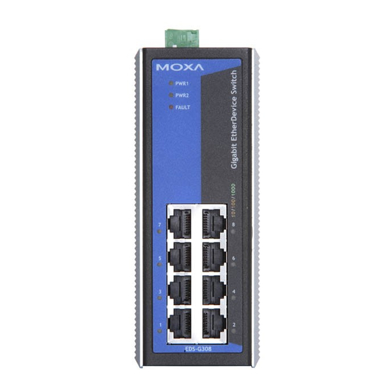
Overview The EDS-G308 series is equipped with 8 Gigabit Ethernet ports and up to 2 fiber optic ports, making it ideal for applications that demand high bandwidth. The EDS-G308 series provides an economical solution for your industrial Gigabit Ethernet connection, and the built-in relay warning function alerts maintainers when power failures or port breaks occur. - Page 3 Panel Layout of EDS-G308/EDS-G308-2SFP EDS-G308 EDS-G308-2SFP Front Panel View Front Panel View Top Panel View 1. Grounding screw 2. Terminal block for power input (PWR1, PWR2) and relay output 3. Power input PWR1 LED 4. Power input PWR2 LED 5. Fault LED 6.
-
Page 4: Mounting Dimensions (Unit = Mm)
Mounting Dimensions (unit = mm) 32.1 18.2 50.4 30.5 Din-Rail 45.8 45.8 31.9 18.2 32.1 Panel Mount Kit DIN-Rail Mounting The aluminum DIN-rail attachment plate should already be fixed to the back panel of the EDS when you take it out of the box. If you need to reattach the DIN-rail attachment plate, make sure the stiff metal spring is situated towards the top, as shown in the figures below. -
Page 5: Atex Information
STEP 2: Mounting the EDS on the wall requires 4 screws. Use the switch, 6.0 mm with wall mount plates attached, as a guide to mark the correct locations of the 4 screws. The heads of the screws should be less 3.5 mm than 6.0 mm in diameter, and the shafts should be less than 3.5 mm in diameter, as shown in the figure at the right. -
Page 6: Wiring Requirements
Wiring Requirements WARNING Safety First! Turn the power off before disconnecting modules or wires. The proper power supply voltage is listed on the product label. Check the voltage of your power source to make sure you are using the correct voltage. Do NOT use a voltage greater than what is specified on the product label. -
Page 7: Wiring The Alarm Contact
Wiring the Alarm Contact The Alarm Contact consists of the two middle contacts of the terminal block on the EDS’s top panel. You may refer to the next section for detailed instructions on how to connect the wires to the terminal block connector, and how to attach the terminal block connector to the terminal block receptor. -
Page 8: Communication Connections
Communication Connections EDS-G308 models have 8 10/100/1000BaseT(X) Ethernet ports, or 6 10/100/1000BaseT(X) and 2 combination ports—10/100/1000T(X) and 100/1000BaseSFP. 10/100/1000BaseT(X) Ethernet Port Connection The 10/100/1000BaseT(X) ports located on Moxa EtherDevice Switch’s front panel are used to connect to Ethernet-enabled devices. Most users will choose to configure these ports for Auto MDI/MDI-X mode, in which case the port’s pinouts are adjusted automatically depending on the type of Ethernet cable used (straight-through or cross-over), and the type of device (NIC-type or... - Page 9 RJ45 (8-pin) to RJ45 (8-pin) Cross-Over Cable Wiring Cross-Over Cable Switch Port Switch Port (NIC Port) (NIC Port) RJ45 Plug Pin 1 RJ45 RJ45 Connector Cable Wiring Connector (Rx+) (Tx+) (Rx-) (Tx-) (Tx+) (Rx+) (Tx-) (Rx-) (DC+) (DD+) (DC-) (DD-) (DD+) (DC+) (DD-)
-
Page 10: Redundant Power Inputs
LC-Port Pinouts LC-Port to LC-Port Cable Wiring Cable Wiring ATTENTION This is a Class 1 Laser/LED product. To avoid causing serious damage to your eyes, do not stare directly into the Laser Beam. Redundant Power Inputs Both power inputs can be connected simultaneously to live AC/DC power sources. -
Page 11: Led Indicators
---- Enables jumbo frame function refers to Jumbo Disables jumbo frame function Frame Enables the corresponding PORT Alarm. If the port’s link fails, the relay will form an open circuit and the fault LED will light up. PORT Alarm Disables the corresponding PORT Alarm. The relay will form a closed circuit and the Fault LED will never light up. -
Page 12: Triple Speed Functionality And Switching
Triple Speed Functionality and Switching The EDS’s 10/100/1000 Mbps RJ45 switched port auto negotiates with the connected device for the fastest data transmission rate supported by both devices. The EDS is a plug-and-play device, so software configuration is not required at installation or during maintenance. The half/full duplex mode for the RJ45 switched ports is user dependent and changes (by auto-negotiation) to full or half duplex, depending on which transmission speed is supported by the attached device. - Page 13 Optical Fiber: 100 or 1000Base SFP modules Gigabit Ethernet SFP-SX SFP-LX SFP-LHX SFP-ZX Wavelength 850nm 1310nm 1310nm 1550nm Max.TX -4 dBm -3 dBm 1 dBm 5 dBm Min.TX -9.5 dBm -9.5 dBm -4 dBm 0 dBm RX Sensitivity -18 dBm -20 dBm -24 dBm 24 dBm...
-
Page 14: Warranty
Humidity Regulatory Approvals Safety UL508(Pending) Hazardous Location UL/cUL Class I, Division 2, Groups A, B, C, and D; ATEX Class I, Zone 2, Ex nC nL IIC T4 (Pending) FCC Part 15, CISPR (EN55022) class A EN61000-4-2 (ESD), Level 3 EN61000-4-3 (RS), Level 3 EN61000-4-4 (EFT), Level 3 EN61000-4-5 (Surge), Level 3...
Need help?
Do you have a question about the EtherDevice EDS-G308 and is the answer not in the manual?
Questions and answers