Moxa Technologies EDS-G205 Hardware Installation Manual
Hide thumbs
Also See for EDS-G205:
- Manual (84 pages) ,
- Hardware installation manual (13 pages) ,
- Hardware installation manual (13 pages)
Table of Contents
Advertisement
Quick Links
Download this manual
See also:
Manual
Advertisement
Table of Contents

Related Manuals for Moxa Technologies EDS-G205


Summary of Contents for Moxa Technologies EDS-G205
- Page 1 EDS-G205 Hardware Installation Guide Moxa EtherDevice Switch Third Edition, April 2014 2014 Moxa Inc. All rights reserved. P/N: 1802002051012...
-
Page 2: Package Checklist
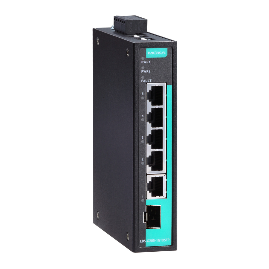
Overview The EDS-G205 series is equipped with 5 Gigabit Ethernet ports, making it an ideal and economical solution for demanding, high bandwidth Gigabit Ethernet applications. In addition, the built-in relay warning function alerts system administrators when power failures or port breaks occur. - Page 3 Panel Layout of EDS-G205 1. Grounding screw 2. Terminal block for power input (PWR1, PWR2) and relay output 3. Power input PWR1 LED 4. Power input PWR2 LED 5. Fault LED 6. TP port’s 10/10/1000 Mbps LED 7. Port number 8.
-
Page 4: Mounting Dimensions
Mounting Dimensions Unit = mm (inch) - 4 -... -
Page 5: Din-Rail Mounting
DIN-Rail Mounting The aluminum DIN-rail attachment plate should already be fixed to the back panel of the EDS when you take it out of the box. If you need to reattach the DIN-rail attachment plate, make sure the stiff metal spring is situated towards the top, as shown in the figures below. -
Page 6: Atex Information
STEP 3: Once the screws are fixed in the wall, insert the four screw heads through the large parts of the keyhole-shaped apertures, and then slide the EDS downwards, as indicated. Tighten the four screws for added stability. ATEX Information 1. - Page 7 WARNING Safety First! Calculate the maximum possible current in each power wire and common wire. Observe all electrical codes dictating the maximum current allowable for each wire size. If the current goes above the maximum ratings, the wiring could overheat, causing serious damage to your equipment. You should also pay attention to the following items: •...
-
Page 8: Wiring The Redundant Power Inputs
Before connecting the EDS to the DC power inputs, make sure the DC power source voltage is stable. Communication Connections EDS-G205 Models have 5 10/100/1000BaseT(X) Ethernet ports. 10/100/1000BaseT(X) Ethernet Port Connection The 10/100/1000BaseT(X) ports located on Moxa EtherDevice Switch’s front panel are used to connect to Ethernet-enabled devices. Most users will choose to configure these ports for Auto MDI/MDI-X mode, in which case the port’s pinouts are adjusted automatically depending on the type... -
Page 9: Redundant Power Inputs
In what follows, we give pinouts for both MDI (NIC-type) ports and MDI-X (HUB/Switch-type) ports. We also give cable wiring diagrams for straight-through and cross-over Ethernet cables. 10 /100Base T(x) RJ45 Pinouts MDI Port Pinouts MDI-X Port Pinouts 8-pin RJ45 Signal Signal 1000BaseT RJ45 Pinouts... -
Page 10: Alarm Contact
Alarm Contact The Moxa EtherDevice Switch has one Alarm Contact located on the top panel. For detailed instructions on how to connect the Alarm Contact power wires to the two middle contacts of the 6-contact terminal block connector, see the Wiring the Alarm Contact section on page 6. A typical scenario would be to connect the Fault circuit to a warning light located in the control room. -
Page 11: Led Indicators
LED Indicators The front panel of the Moxa EtherDevice Switch contains several LED indicators. The function of each LED is described in the table below. Color State Description Power is being supplied to power input PWR1 PWR1 AMBER Power is not being supplied to power input PWR1 Power is being supplied to power input PWR2... -
Page 12: Auto-Negotiation And Speed Sensing
Auto-Negotiation and Speed Sensing The EDS’s RJ45 Ethernet ports independently support auto-negotiation for transmission speeds of 10 Mbps, 100 Mbps, and 1000 Mbps, with operation according to the IEEE 802.3 standard. This means that some nodes could be operating at 10 Mbps, while at the same time, other nodes are operating at 100 Mbps or 1000Mbps. - Page 13 FCC Part 15, CISPR (EN 55022) class A EN 61000-4-2 (ESD), Level 3 EN 61000-4-3 (RS), Level 3 EN 61000-4-4 (EFT), Level 3 EN 61000-4-5 (Surge), Level 3 EN 61000-4-6 (CS), Level 3 EN 61000-4-8 EN 61000-4-11 EN 61000-4-12 Shock IEC 60068-2-27 Free Fall IEC 60068-2-32...
Need help?
Do you have a question about the EDS-G205 and is the answer not in the manual?
Questions and answers