
Related Manuals for Moxa Technologies EDS-405


Summary of Contents for Moxa Technologies EDS-405
- Page 1 Moxa EtherDevice™ Switch EDS-405 User’s Manual Fifth Edition, June 2008 © 2008 Moxa Inc., all rights reserved. Reproduction without permission is prohibited.
- Page 2 Moxa EtherDevice Switch EDS-405 User’s Manual The software described in this manual is furnished under a license agreement and may be used only in accordance with the terms of that agreement. Copyright Notice Copyright © 2008 Moxa Inc. All rights reserved.
- Page 3 Technical Support Contact Information www.moxa.com/support Moxa Americas: Moxa China (Shanghai office): Toll-free: 1-888-669-2872 Toll-free: 800-820-5036 Tel: +1-714-528-6777 Tel: +86-21-5258-9955 Fax: +1-714-528-6778 Fax: +86-10-6872-3958 Moxa Europe: Moxa Asia-Pacific: Tel: +49-89-3 70 03 99-0 Tel: +886-2-8919-1230 Fax: +49-89-3 70 03 99-99 Fax: +886-2-8919-1231...
-
Page 4: Table Of Contents
Overview ................1-2 Package Checklist ............1-3 Product Features ............. 1-3 Panel Layout of EDS-405..........1-4 Panel Layout of EDS-405-MM/SS-SC......1-5 Panel Layout of EDS-405-MM-ST ........ 1-6 Chapter 2 Installing EDS-405 ...........2-1 Mounting Dimensions ............. 2-2 DIN-Rail Mounting ............2-3 Wall Mounting (Optional) .......... - Page 5 Basic Switching Function ..........4-11 Auto MDI/MDI-X Connection ......4-11 Fiber Ports ............4-11 Dual Speed Functionality and Switching..4-12 Switching, Filtering, and Forwarding ....4-12 Switching and Address Learning...... 4-13 Auto-Negotiation and Speed Sensing ..... 4-13 Appendix A Product Specifications........A-1...
-
Page 6: Chapter 1 Introduction
Introduction Chapter 1 Welcome to Moxa EDS-405 Series, the new generation of EtherDevice™ Switch that comes with “Moxa Turbo Ring,” developed by Moxa for industrial Ethernet switches. With this plug-n-play ring redundancy solution, your industrial automation and control applications can operate non-stop. -
Page 7: Overview
EDS-405 has a wide operating temperature range of -40 to 75°C, and is designed to withstand a high degree of vibration and shock. The rugged hardware design... -
Page 8: Package Checklist
Introduction Package Checklist Moxa EDS-405 is shipped with the following items: Standard Accessories 1 Switch: EDS-405, EDS-405-MM-SC, EDS-405-SS-SC, or EDS-405-MM-ST EDS-405 User’s Manual Product Warranty Booklet Protective caps for unused ports Optional Accessories WK-46 Wall Mounting Kit NOTE: Notify your sales representative if any of the above items is missing or damaged. -
Page 9: Panel Layout Of Eds-405
EDS-405 User’s Manual Panel Layout of EDS-405 Top View Grounding screw PWR2 Terminal block for power input FAULT PWR1 PWR1/PWR2 and relay output V1 V2 INPUTS 12-48 VDC Heat dissipation orifices Dip switches PORT ALARM RING MASTER Power input PWR1 LED... -
Page 10: Panel Layout Of Eds-405-Mm/Ss-Sc
Introduction Panel Layout of EDS-405-MM/SS-SC Top View NOTE: The appearance of PWR2 EDS-405-SS-SC is identical to FAULT PWR1 EDS-405-MM-SC. V1 V2 INPUTS 12-48 VDC Grounding screw PORT ALARM Terminal block for power input RING MASTER PWR1/PWR2 and relay output Heat dissipation orifices... -
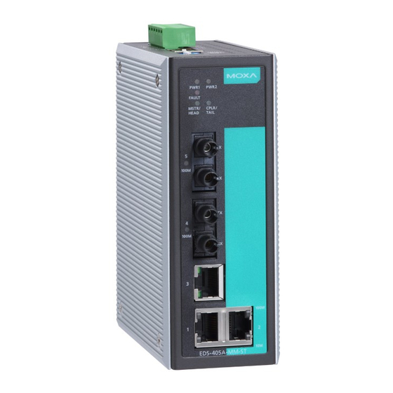
Page 11: Panel Layout Of Eds-405-Mm-St
EDS-405 User’s Manual Panel Layout of EDS-405-MM-ST Top View Grounding screw PWR2 Terminal block for power input FAULT PWR1 PWR1/PWR2 and relay output V1 V2 INPUTS 12-48 VDC Heat dissipation orifices Dip switches PORT ALARM RING MASTER Power input PWR1 LED... -
Page 12: Installing Eds-405
Installing EDS-405 Chapter 2 This chapter includes information about how to install EDS-405. The following topics are covered: Mounting Dimensions DIN-Rail Mounting Wall Mounting (Optional) -
Page 13: Mounting Dimensions
EDS-405 User’s Manual Mounting Dimensions 21.00 30.00 54.00 9.50 Side View 135.00 (unit = mm) 105.00 15.10 13.90 13.90 13.10 18.20 25.40 9.75 3.50 6.00 3.50 PWR1 6.00 PWR2 FAULT 30.50 7.75 7.75 RING MASTER 135.00 EDS-405 Front View Rear View... -
Page 14: Din-Rail Mounting
The aluminum DIN-Rail attachment plate should already be fixed to the back panel of EDS-405 when you take it out of the box. If you need to reattach the DIN-Rail attachment plate to EDS-405, make sure the stiff metal spring is situated towards the top, as shown in the figures below. -
Page 15: Wall Mounting (Optional)
EDS-405 User’s Manual Wall Mounting (Optional) For some applications, you will find it convenient to mount EDS-405 on the wall, as illustrated below. 1. Remove the aluminum DIN-Rail attachment plate from EDS-405’s rear panel, and then attach the wall mounting plates, as shown in the diagram below. - Page 16 Installing EDS-405 3. Once the screws are fixed in the wall, insert the four screw heads through the large parts of the keyhole-shaped apertures, and then slide Moxa EDS-405 downwards, as indicated below. Tighten the four screws for stability. PWR1...
-
Page 17: Wiring Eds-405
Wiring EDS-405 Chapter 3 This chapter includes information about wiring EDS-405. The following topics are covered: Wiring Requirements Grounding EDS-405 Wiring the Alarm Contact Wiring the Redundant Power Inputs Communication Connections 10/100BaseT(X) Ethernet Port Connection 100BaseFX Fiber Port Connection... -
Page 18: Wiring Requirements
EDS-405 User’s Manual Wiring Requirements In this section, we point out several items that you should pay attention to before proceeding with your installation. WARNING Do not disconnect modules or wires unless the power supply has been switched off or the area is known to be non-hazardous. The devices may only be connected to the supply voltage shown on the type plate. - Page 19 Wiring EDS-405 ATTENTION This unit is a built-in type. When the unit is installed in another piece of equipment, the equipment enclosing the unit must comply with fire enclosure regulation IEC 60950/EN60950 (or similar regulation). ATTENTION Safety First! Be sure to disconnect the power cord before installing and/or wiring your Moxa EtherDevice Switch.
-
Page 20: Grounding Eds-405
The Alarm Contact consists of the two middle contacts of the terminal block on EDS-405’s top panel. To wire the Alarm Contact, use 2 wires and connect one end of the wires to EDS-405’s alarm contract. The other end of the 2 wires should be connected to your alarm devices. -
Page 21: Wiring The Redundant Power Inputs
The top right and left two contacts and the bottom two contacts of the 6-contact terminal block connector on EDS-405’s top panel are used for EDS-405’s two DC inputs. Top and front views of one of the terminal block connectors are... -
Page 22: Communication Connections
EDS-405’s top panel. EDS-405 has dual power inputs that can be connected simultaneously to live DC power sources. If one power source fails, the other live source acts as a backup, and automatically supplies all of Moxa EDS-405’s power needs. - Page 23 Wiring EDS-405 RJ45 (8-pin, MDI) Port Pinouts RJ45 (8-pin, MDI-X) Port Pinouts 8-Pin Description 8-Pin Description RJ45 (8-pin) to RJ45 (8-pin) Straight-Through Cable Wiring Straight-Through Cable Switch Port NIC Port RJ45 Plug Pin 1 RJ45 RJ45 Connector Cable Wiring Connector...
-
Page 24: 100Basefx Fiber Port Connection
EDS-405 User’s Manual 100BaseFX Fiber Port Connection The concept behind the SC/ST port and cable is quite straightforward. Suppose you are connecting devices I and II. Contrary to electrical signals, optical signals do not require a circuit in order to transmit data. Consequently, one of the optical lines is used to transmit data from device I to device II, and the other optical line is used to transmit data from device II to device I, for full-duplex transmission. - Page 25 Wiring EDS-405 ATTENTION This is a Class 1 Laser/LED product. Do not stare directly into the Laser/LED beam.
-
Page 26: How To Use Eds-405
How to Use EDS-405 Chapter 4 In this chapter, we give a general idea of how to use EDS-405. Some users will simply want to plug in the power, connect the switch to their Ethernet-enabled devices, and then go to work right away. Other users will want to utilize EDS-405’s basic device management functions, whereas some will want to make... -
Page 27: Supported Ethernet Network Topologies
EDS-405 User’s Manual Supported Ethernet Network Topologies Redundant Ring Topology Moxa developed the proprietary Turbo Ring protocol for better network reliability and faster recovery time. Moxa Turbo Ring’s recovery time is less than 300 ms compared to a 3- to 5-minute recovery time for commercial switches, decreasing the possible loss caused by network failures in an industrial setting. -
Page 28: Star-Wired Topology
How to Use EDS-405 Star-Wired Topology EDS-405 can also be used to form a star-wired topology, as shown below. Since ports 4 and 5 of EDS-405 are programmed to recognize the Turbo Ring topology immediately, when using a star-wired topology, you might have to wait for the EDS-405s to negotiate and recognize that port 4 and port 5 are not being used to form a Turbo Ring topology. -
Page 29: Moxa Turbo Ring Setup
4 or 5 of one switch to port 4 or 5 of a neighboring switch. EDS-405 does not support ring coupling. There are 6 Dip Switches on the top panel of EDS-405. The default setting of the Dip Switches is OFF. Dip Switches 1 to 5 are for enabling Port Alarms. - Page 30 NOTE EDS-405’s ports 4 and 5 are used to form the Turbo Ring. When forming the Turbo Ring, connect port 4 or 5 of one EDS-405 to port 4 or 5 of the adjacent EDS-405.
- Page 31 EDS-405 User’s Manual When the number of EDS units in the Turbo Ring is odd. Master If there are 2N+1 EDS port 4/5 PWR1 port 4/5 PWR2 FAULT units (an odd number) in RING MASTER PWR1 PWR1 the Turbo Ring, then the...
-
Page 32: Front Panel Led Indicators
When the corresponding PORT alarm is FAULT enabled and the port’s link is active, or when the corresponding PORT alarm is disabled. When the EDS-405 is the Master of this Turbo Ring. RING Green When the EDS-405 is Ring Master of the... -
Page 33: Dip Switch Settings
P1-P5 Disables the corresponding PORT Alarm. The relay will form a closed circuit and the Fault LED will never light up. RM Disables this EDS-405 from being the Ring Master in a Turbo Ring topology, and disables the Turbo Ring break alarm. If the EDS-405 is the Master of this Turbo Ring, and the Turbo Ring is broken, the relay will form a closed circuit. -
Page 34: Upgrading The Firmware
2. Unzip the EDS-405 Utility zip file. 3. Run the EDS-405 Utility Setup file. 4. After the installing the EDS-405 Utility, make sure that the EDS-405 is correctly installed and connected as described in Chapter 3. 5. Select Broadcast Search from the EDS-405 Utility to locate the EDS-405. - Page 35 7. After you click on the Upgrade Firmware button, the next window that opens will ask you to locate the EDS-405.rom file you just downloaded. 8. Locate the EDS-405.rom file and click on OPEN to start upgrading the new version of the firmware.
-
Page 36: Basic Switching Function
10/100BaseTX ports to any kind of Ethernet device, without paying attention to the type of Ethernet cable being used for the connection. This means that you can use either a straight-through cable or cross-over cable to connect the EDS-405 to Ethernet devices. -
Page 37: Dual Speed Functionality And Switching
Dual Speed Functionality and Switching EDS-405’s 10/100 Mbps switched RJ45 port auto negotiates with the connected device for the fastest data transmission rate supported by both devices. All models of EDS-405 Series are plug-and-play devices, so that software configuration is not required at installation, or during maintenance. -
Page 38: Switching And Address Learning
Switching and Address Learning EDS-405 Series products have an address table that can hold up to 1000 node addresses, making them suitable for use with large networks. The address tables are self-learning, so that as nodes are added or removed, or moved from one segment to another, EDS-405 automatically keeps up with new node locations. -
Page 39: Product Specifications
Product Specifications Appendix A Technology Standards IEEE802.3, 802.3u, 802.3x Processing Type Store and Forward, with IEEE802.3x full duplex, back pressure flow control Address Table Size 1K uni-cast addresses Interface LED Indicators Power, Fault, 10/100M, Ring Master DIP Switch Port break alarm mask, Ring master Alarm Contact One relay output with current carrying capacity of 1A @ 24 RJ45 Ports... - Page 40 EDS-405 User’s Manual Power Requirements Power Input 12 to 48 VDC, redundant dual DC power inputs Connection Removable terminal block Overload Current Protection Present Reverse Polarity Protection Present Mechanical Casing IP30 protection, metal case Dimensions 53.6 x 135 x 105 mm (W x H x D) Weight 0.65 kg...
Need help?
Do you have a question about the EDS-405 and is the answer not in the manual?
Questions and answers