
Related Manuals for Primus C 6


Summary of Contents for Primus C 6
- Page 1 C 6/8 INSTALLATION AND MAINTENANCE MANUAL SOFT MOUNTED WASHER EXTRACTOR PUBLICATION DATE : Jan 06 WITH ELECTRONIC PROGRAMMER 516574...
-
Page 2: Table Of Contents
1. TABLE OF CONTENS Publication date 01/06 Page: 1. TABLE OF CONTENS ....................1 2. WARNINGS ........................2 2.1. DURING TRANSPORTATION AND STORAGE..................2 2.2. MACHINE SYMBOLS .........................2 3. TECHNICAL INFORMATION ..................3 3.1. TECHNICAL INFORMATION......................3 4. MACHINE INSTALLATION ................... 6 4.1. -
Page 3: Warnings
2. WARNINGS TO MINIMIZE THE RISK OF FIRE, INJURY BY ELECTRIC SHOCK OR SERIOUS INJURIES TO PEOPLE OR PROPERTY DAMAGE, PLEASE READ AND FOLLOW THE FOLLOWING INSTRUCTIONS. – This English version is the original version. Without this version, the instructions are incomplete. Complete instructions consist of „User´s manual“, „Installation and Maintenance manual“... -
Page 4: Technical Information
3. TECHNICAL INFORMATION 3.1. TECHNICAL INFORMATION DIMENSIONS CAPACITY: 6 kg / 13 lb 7,5 kg / 16,5 lb PACKING DIMENSIONS: width 730 mm / 28,74“ 750 mm / 29,52“ depth 730 mm / 28,74“ 760 mm / 29,92“ height 1200 mm / 47,24“ 1200 mm / 47,24“... - Page 5 HEATING Types of heating: cold soft / hot soft water - without electric heating cold soft / additional hot soft water - with electric heating 2750 W - with electric heating 6000 W - with electric heating 9000 W CONNECTION WATER CONNECTION: water pressure 0.1 –...
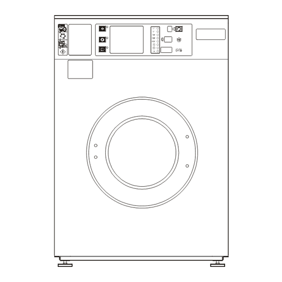
- Page 6 6 kg / 13 lb 7,5 kg / 16,5 lb 11. Connection of hot water 1. Door open push button 2. F push button 12. „Program/run“ mode push button 3. START push button 13. Serial plate 4. Card of wash programs 14.
-
Page 7: Machine Installation
4. MACHINE INSTALLATION 4.1. MANIPULATION AND UNPACKING DURING TRANSPORTATION All doors and passages the machine is to be transported through during installation must be reasonably dimensioned to meet the width, height and depth off the machine including the package. The machine dimensions are stated in chapter „3.Technical information“. -
Page 8: Transporting Braces
1. U-profile 2. Lever of emergency door opening Fig.4.3. Bottom machine frame 4.4. TRANSPORTING BRACES Dismantle the rear cover. Before complete removal of the rear panel it is necessary to disconnect the ventilation hose of the machine. It means loosen the hose clip and pull the rubber hose off the plastic socket. There are two striking colour transporting braces which must be removed before putting the machine into operation. -
Page 9: Connection
4.5. CONNECTION ELECTRICAL CONNECTION WARNING ! THE MACHINE MUST BE CONNECTED TO THE POWER, GROUND, WATER, VENTILATION AND STEAM SUPPLY ACCORDING TO THE INSTALLATION MANUAL, IN COMPLIANCE WITH THE VALID LOCAL STANDARDS DONE BY QUALIFIED TECHNICIANS WITH PROPER AUTHORIZATION. THE VALID STANDARDS FOR CONNECTING TO THE LOCAL POWER NETWORK (TT / TN / IT, ...) MUST BE FOLLOWED. -
Page 10: Install Supply Cable To The Machine
INSTALL SUPPLY CABLE TO THE MACHINE WARNING ! THE PROTECTIVE CONDUCTOR MUST BE LONGER SO THAT WHEN THE CABLE IS PULLED OUT ACCIDENTALLY, THIS CONDUCTOR IS DISCONNECTED AS THE LAST ONE! 1. Green-yellow - protection conductor PE 4. Black - phase conductor 5. -
Page 11: Preparing The Machine For Operation
WATER DRAIN CONNECTION The machine is equipped with drain valve or optional with pump. – for the machine equipped with drain valve; connect the drain pipe to the drain valve by means of included clamp. The main drain pipe must have the capacity to be able to handle the total output of all connected machines. -
Page 12: Maintenance And Adjustments
5. MAINTENANCE AND ADJUSTMENTS WARNING ! ALWAYS FOLLOW SAFETY INSTRUCTIONS! DO NOT BYPASS ANY SAFETY DEVICES OR THEIR PARTS. ANY INTERFERENCE TO THE MACHINE FUNCTIONS AND CONSTRUCTION ARE PROHIBITED! USE THE PROPER CHEMICAL AGENTS WHICH AVOID CALCIUM SEDIMENTS ON HEATING ELEMENTS AND OTHER MACHINE PARTS. -
Page 13: Adjustments And Part´s Exchanges
1. Plug of emergency drain 2. Pump cover Fig. 5.1. Drain pump 3. Check for the belt tightness or possible damage; therefore remove the machine rear cover. 4. Check visually all hoses and connection inside the machine for leaking. 5. Check the condition and tightness of bolt joints (fig.5.2.C,pos.7 and 8) which hold the trunnion. 5.2. -
Page 14: Replacement Of Door Rubber
REPLACEMENT OF DOOR RUBBER 1. Open the door. Remove the door glass (fig.5.2., pos.5) with rubber (4) from the stainless steel door (7) by pushing it towards the drum. Do it carefully, not to damage the glass. Remove the seal (4) from the glass. 2. - Page 15 1. Securing bolt with nut 2. Motor 3. Motor pulley 4. Motor pivot 5. Belt 6. Drum pulley 7. M10 bolt joint of the hub 8. M8 bolt joint of the hub Fig.5.2.C Machine drive FUSES Fuses FU1, FU2 for controlling circuits have value 6.3 A - 250 V. The fuses are accessible from the machine rear, (fig.3.1., pos.15).
-
Page 16: Trouble Shooting Aids
6. TROUBLE SHOOTING AIDS 6.1. MACHINE IS NOT STARTING – No electrical power: – check the fuses – check that the plug is inserted correctly into the socket – turn the „O / I“ switch located in front at ON position (I). –... -
Page 17: Failure Led Is Flashing
6.10. FAILURE LED IS FLASHING – the second digital line indicates the error code which is stated in the programming manual 6.11. DOOR FAILS TO OPEN In case of a power failure or an emergency situation, proceed as follows: 1. before the door is open, check the washing bath and machine parts temperature. WARNING ! IF TOO HOT DO NOT OPEN! RISK OF BURN OR SCALD INJURIES ! KEEP CHILDREN OFF WHEN THE MACHINE IS IN OPERATION ! -
Page 18: Drawings, Lists And Diagrams For Maintenance
7. DRAWINGS, LISTS AND DIAGRAMS FOR MAINTENANCE 7.1. SCHEMES FOR INSPECTION AND CHECKING OF CORRECT OPERATION Schemes for installation of the machine are supplied with the machine. 7.2. LIST OF RECOMMENDED SPARE PARTS Find more detailed information in the spare part manual of the machine. PRI 610 000 075 Door lock PRI 401 002 022... -
Page 19: Putting The Machine Out Of Service
8. PUTTING THE MACHINE OUT OF SERVICE 8.1. DISCONNECTING THE MACHINE 1. Disconnect the outer electric power supply from the machine. 2. Turn off the outer water inlet. 3. Make sure, the inlets of power supply and water are closed. Disconnect all power and water inlets. 4. -
Page 20: Serial Number
IMPORTANT ! MACHINE TYPE: PROGRAMMER: -ELECTRONIC TIMER INSTALLATION DATE: INSTALLATION CARRIED OUT BY: SERIAL NUMBER: ELECTRICAL DETAILS: .....VOLT....PHASE....HZ NOTE: ANY CONTACTS WITH YOUR DEALER REGARDING MACHINE SAFETY, OR SPARE PARTS, MUST INCLUDE THE ABOVE IDENTIFICATION. MAKE CERTAIN TO KEEP THIS MANUAL IN A SECURE PLACE FOR FUTURE REFERENCE.
Need help?
Do you have a question about the C 6 and is the answer not in the manual?
Questions and answers