
Related Manuals for Primus FS 6-16


Summary of Contents for Primus FS 6-16
- Page 1 FS 6-16 INSTALLATION AND MAINTENANCE MANUAL SOFT MOUNTED WASHER EXTRACTOR PUBLICATION DATE : 05/02 WITH ELECTRONIC PROGRAMMER 100646...
-
Page 2: Table Of Contents
1. TABLE OF CONTENTS Publication date : 05/02 1. TABLE OF CONTENTS ....................1 2. WARNINGS ........................2 3. TECHNICAL INFORMATION ..................3 4. MACHINE INSTALLATION ................... 7 4.1. MACHINE INSPECTION ........................7 4.2. MACHINE STORAGE.........................7 4.3. MACHINE POSITIONING ........................7 4.3.1 FREELY ON THE FLOOR......................8 4.3.2 FREELY ON AN ELEVATION. -
Page 3: Warnings
2. WARNINGS FAILURE TO COMPLY WITH THE INSTRUCTIONS IN THIS MANUAL MAY LEAD TO INCORRECT USE OF THE WASHER EXTRACTOR, AND MAY RESULT IN BODILY INJURIES OR DEATH AND/OR DAMAGE TO THE LAUNDRY AND/OR THE WASHER EXTRACTOR. ♦ This English version is the original version. ♦... -
Page 4: Technical Information
3. TECHNICAL INFORMATION 165L LOAD CAPACITY OF DRY 6 kg/13,2 lb 10 kg/21 lb 16.5 kg/36.4 lb 7,3 kg/16.1 lb LINEN (1/10) DIMENSIONS CABINET DIMENSIONS Width 660 mm/25.98" 660 mm/25.98" 660 mm/25.98" 830 mm/32.6” Depth 680 mm/26.77" 680 mm/26.77" 780 mm/30.71” 960 mm/37.8”... - Page 5 CONNECTION WATER CONNECTION Water pressure 0.1-0.8 MPa/ 0.1-0.8 MPa / 0.1-0.8 MPa / 0.1-0.8 MPa / 1-8 bar / 1-8 bar / 1-8 bar / 1-8 bar / 14.5-116 PSI 14.5-116 PSI 14.5-116 PSI 14.5-116 PSI Recommended water pressure 0.25 MPa / 0.25 MPa / 0.25 MPa / 0.25 MPa /...
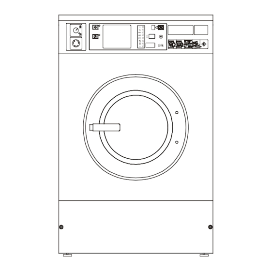
- Page 6 60/75/95 L machines 165 L machine with frequency control drive Fig. 3.1. 1. Control panel 8. Main switch 2. Connection liquid soap 9. Electrical supply connection 3. Serial plate 10. Drain 4. Soap hopper venting 11. Adjustable leg 5. Water supply 12.
- Page 7 CAPACITY 60L CAPACITY 75L CAPACITY 95L CAPACITY 165L 660 mm / 25.98” 660 mm / 25.98” 660 mm / 25.98” 830 mm / 32.68” 685 mm / 26.97” 685 mm / 26.97” 785 mm / 30.91” 960 mm / 37.8” 1070 mm / 42.13”...
-
Page 8: Machine Installation
4. MACHINE INSTALLATION 4.1. MACHINE INSPECTION When the machine is delivered, it is necessary to do a visual inspection for any damage that may have occurred during transit. If the package or pallet are damaged or signs of possible damage are evident, let the carrier note the condition on the shipping papers before the shipping receipt is signed. -
Page 9: Freely On The Floor
4.3.1 FREELY ON THE FLOOR The machine is to be located on a not elevated leveled concrete floor that comply with static and dynamic stress of the machine. The friction coefficient must be higher then 0,5 between the rubber feet and the floor material. Do not place the machine on a smooth surface but on a rough floor material like concrete. -
Page 10: Fixed On An Elevation
4.3.3 FIXED ON AN ELEVATION The machine can also be secured to a mounting base or foundation by means of bolts and anchoring bolts to assure the safety. When a concrete pad or a frame is used then is the maxium height 305 mm (12”). The pad or frame must be designed so that it can carry the static and dynamic forces. -
Page 11: Leveling The Machine
Capacity 60L Capacity 75L Capacity 95L Capacity 165L 660 mm / 25.98” 660 mm / 25.98” 660 mm / 25.98” 830 mm / 32.7” 560 mm / 22.05” 560 mm / 22.05” 560 mm / 22.05” 715 mm / 28.1” 50 mm / 1.97”... - Page 12 After removing the shipping bars put the service panel, fig. 4.4. pos 3 and the rear panel, fig. 4.4. pos 4 back on the machine. Keep the shipping bars pos 1,2 for possible future transportation. Fig. 4.4. Transporting braces 100 646 PUB.DATE : 05/02 INSTALLATION AND MAINTENANCE MANUAL...
-
Page 13: Electrical Connection
4.5. ELECTRICAL CONNECTION WARNING ! THE MACHINE MUST BE CONNECTED TO THE POWER, GROUND, WATER, VENTILATION AND STEAM SUPPLY ACCORDING TO THE INSTALLATION MANUAL, IN COMPLIANCE WITH THE LOCAL STANDARDS DONE BY QUALIFIED TECHNICIANS WITH PROPER AUTHORIZATION. THE VALID STANDARDS FOR CONNECTING TO THE LOCAL POWER NETWORK (TT / TN / IT, ...) MUST BE FOLLOWED. - Page 14 ELECTRIC HEATING: Without EXECUTION: electrical 6000 W 9000 W 12000 W 18000 W heating Fuse cross Fuse cross Fuse cross Fuse cross Fuse cross breaker section breaker section breaker section breaker section breaker section 1AC 220-240V 2xD16 2 + 1 2.5mm²...
-
Page 15: Checking Rotation Direction
CHECKING ROTATION DIRECTION CHECK IF THE DRUM ROTATES FROM THE FRONT VIEW IN CLOCKWISE DIRECTION DURING EXTRACTION. IF IT ROTATES IN OPPOSITE DIRECTION, DISCONNECT TWO PHASES OF THE CONNECTION FROM THE FREQUENCY CONVERTOR TO THE MOTOR , SWITCH THEM OVER AND CHECK AGAIN THE ROTATION DIRECTION. -
Page 16: Connection Of Water Supplies
4.6. CONNECTION OF WATER SUPPLIES WATER CONNECTION WATER HARDNESS It is advisable to contact the water supplier for information concerning the properties of the water in your area. Good wash results are dependent also on the water hardness. For medium to very hard water, consideration should be made to make the water softer. -
Page 17: Water Drain Connection
WATER DRAIN CONNECTION The machine is equipped with a drain valve of 75 mm (3”) diameter. The drain is situated on the rear of the machine. The drain has to be connected to the waste channel. You can use the elbow, which is a part of the delivery. -
Page 18: Connection Of Liquid Washing Soaps Dosing
AIR VENT CONNECTION WARNING! WATCH OUT FOR STEAM ESCAPE FROM THE MACHINE VENTING ! DO NOT COVER THE MACHINE VENTING; IT SERVES AS A STEAM OUTLET AND MACHINE VENTING. IT ALLOWS A PROPER MEASURING OF THE LEVEL.. On the backside, the machine is provided with a drum air vent terminal (see fig. 3.1 pos 4) of external diameter 75 mm (3"). -
Page 19: Preparing The Machine For Operation
WARNING ! CHECK IF THE HOSES ARE TIGHTEN BY THE CLAMPS ! ANY LEAKAGE OF CHEMICALS MAY CAUSE CORROSION ON THE PARTS IN THE MACHINE. The liquid soap pump system supply needs to be connected to an external electrical source. Only authorised workers with a valid qualification must execute the electrical connection of the machine according to the valid local standards. -
Page 20: Maintenance And Adjustments
5. MAINTENANCE AND ADJUSTMENTS WARNING ! ALWAYS FOLLOW SAFETY INSTRUCTIONS! DO NOT BYPASS ANY SAFETY DEVICES OR THEIR PARTS, ANY INTERFERENCE TO THE MACHINE FUNCTIONS AND CONSTRUCTION ARE PROHIBITED. BEFORE MAINTENANCE WORK DISCONNECT THE MACHINE POWER SUPPLY. In case of serious failures call the technical service of your supplier. When replacing any parts of the machine, exchange them with original parts obtained from your dealer or ordered through the spare parts catalogue. -
Page 21: Adjustments And Part´s Exchanges
5.2. ADJUSTMENTS AND PART´S EXCHANGES ADJUSTMENT OF DOOR SEAL THRUST For 60, 75, 95 liter machines If there is a water leakage around the door it is necessary to find out if the problem has been caused due to the door shift out of its position or if the door seal thrust should be adjusted. In some cases the door seal has to be replaced.(Fig. -
Page 22: Replacement Of Door Rubber
REPLACEMENT OF DOOR RUBBER For 60, 75, 95 liter machines 1. Open the door. Remove the door glass (Fig. 5.2.A, pos.3) with rubber (pos 2) from the stainless steel door (pos 5) by pushing it towards the drum. Do it carefully, do not damage the glass. 2. - Page 23 1. Microswitch 2. Limiter 3. Sensor Fig. 5.2.C. Vibration switch REPLACEMENT / REGULATION OF THE BEL T WARNING! MAKE SURE THE MACHINE IS DISCONNECTED FROM POWER SUPPLY BY PULLING OUT THE PLUG FROM THE SOCKET. On a new machine and after a belt replacement, make an inspection of the belt tightness : 1.
-
Page 24: Water Filters
4. After the belt replacement, check the pulley alignment, the tightness of belts, bolts and nuts. Keep the belts and pulleys clean and free of oil, lubricants, water etc. 1. Rear panel 2. 2 x Belt 3. 2 x Screw M12 : Alignment 4. - Page 25 FUSES The internal fuses FU1, FU2 for controlling circuits have value 1 A (230V or 400V) and dimension L=32 mm and ∅ = 6,3mm. The fuses are accessible from the machine rear, fig. 3.1, pos. 7. PUTTING THE MACHINE OUT OF SERVICE 1.
-
Page 26: Troubleshooting Aids
6. TROUBLESHOOTING AIDS 6.1. ERROR HANDLING The timer allows the full control of the washing machine. When an error occurs then automatically the machine will go over to a safe state. With the diagnostic program you can determine the problem ( See Program manual). - Page 27 Problem Cause Solving the problem or disabled • the infrared key is not functional the input connector and the keyswitch • set the menu-item, Ir = On use the key switch at a distance less then 0,5 meter and in front of check the battery (the LED of the infrared key is eluminated when the button is pressed) The machine is not behaving as...
-
Page 28: Door Fails To Open
Problem Cause Solving the problem installed • reinstall vibration switch • the suspension is damaged, the shock absorbers are cold • change the shock absorbers Door fails to open • a fault is occurred • wait until the counter has reached ‘0’ •... -
Page 29: List Of Recommended Spare Parts
7. LIST OF RECOMMENDED SPARE PARTS Find more detailed information in the spare part manual for individual machines. Drain valve 3” 230V 2-way water inlet valve 3-way water inlet valve Rubber for door glass Micro switch 83.161.9 Rubber tub housing Contactor LC1 D09 019M7 (9A) Contactor LC1 D12 019M7 (12A) Contactor LC1 D18 01M7 (18A) -
Page 30: Putting The Machine Out Of Service
8. PUTTING THE MACHINE OUT OF SERVICE DISCONNECTING THE MACHINE 1. Disconnect the outer electric power supply from the machine. 2. Switch off the main switch located on the back of the machine. 3. Turn off the outer water or steam inlet. 4. -
Page 31: Serial Number
IMPORTANT ! MACHINE TYPE: PROGRAMMER: -EASY CONTROL -FULL CONTROL INSTALLATION DATE: INSTALLATION CARRIED OUT BY: SERIAL NUMBER: ELECTRICAL DETAILS: .....VOLT....PHASE....HZ NOTE: ANY CONTACTS WITH YOUR DEALER REGARDING MACHINE SAFETY, OR SPARE PARTS, MUST INCLUDE THE ABOVE IDENTIFICATION. MAKE CERTAIN TO KEEP THIS MANUAL IN A SECURE PLACE FOR FUTURE REFERENCE.
Need help?
Do you have a question about the FS 6-16 and is the answer not in the manual?
Questions and answers