
Related Manuals for Primus F 22-55


Summary of Contents for Primus F 22-55
- Page 1 F/FS 22-55 INSTALLATION AND MAINTENANCE INSTRUCTIONS INDUSTRIAL WASHER- PUB DATE: 03/02 EXTRACTORS 504 766...
-
Page 2: Table Of Contents
1. CONTENTS Publication date 03/02 Page: CONTENTS ........................1 2. WARNINGS AND SYMBOLS ..................2 2.1. PERSONAL SAFETY RULES......................2 2.2. SYMBOLS ON THE MACHINE......................2 2.3. IMPORTANT INFORMATION BEFORE INSTALLATION ..............3 3. TECHNICAL SPECIFICATION ..................4 3.1. MACHINES WITH 22kg / 50lbs CAPACITY..................4 3.2. -
Page 3: Publication Date
2. WARNINGS AND SYMBOLS TO MINIMIZE THE RISK OF FIRE, INJURY BY ELECTRIC SHOCK OR SERIOUS INJURIES OF PERSONS OR PROPERTY DAMAGE, PLEASE READ AND FOLLOW THE FOLLOWING INSTRUCTIONS: 2.1. PERSONAL SAFETY RULES GENERALLY – This English version is the original version. –... -
Page 4: Important Information Before Installation
2.3. IMPORTANT INFORMATION BEFORE INSTALLATION FOR TRANSPORTATION AND STORAGE IN CASE OF TRANSPORTATION AND STORAGE, WATCH COMPONENTS PROTRUDING FROM THE CONTOUR LINE OF MACHINE (DOOR LOCKS ETC.), TO AVOID INJURIES. – Never push, pull or exert pressure on components protruding from the machine contour line (controls, door locks etc.). -
Page 5: Technical Specification
3. TECHNICAL SPECIFICATION 3.1. MACHINES WITH 22kg / 50lbs CAPACITY 1-Motor version 2-Motor version 22kg / 50lbs CAPACITY: DIMENSIONS PACKING DIMENSIONS: width 1100 mm / 43,3“ depth 1260 mm / 49,6“ height 1920 mm / 75,6“ transportation capacity 2,66 m / 99,90 ft MACHINE DIMENSIONS: width... - Page 6 1-Motor version 2-Motor version 22kg / 50lbs CAPACITY: WASHING FUNCTION RPM OF THE DRUM: washing 7 - 50 rpm 42 rpm distribution 90 rpm 90 rpm low spinning 435 rpm high spinning 301 - 860 rpm 860 rpm G - factor of spinning max.
-
Page 7: Machines 33Kg / 80Lbs Capacity
3.2. MACHINES 33kg / 80lbs CAPACITY 1-Motor version 2-Motor version 33kg / 75lbs CAPACITY: DIMENSIONS PACKING DIMENSIONS: width 1430 mm / 56,3“ depth 1475 mm / 58,1“ height 2105 mm / 82,87“ transportation capacity 4,4 m / 156 ft MACHINE DIMENSIONS: width 1195 mm / 47,04“... - Page 8 1-Motor version 2-Motor version 33kg / 75lbs CAPACITY: WASHING FUNCTION RPM OF THE DRUM: washing 7 - 50 rpm 36 rpm distribution 90 rpm 59 rpm low spinning 435 rpm high spinning 301 - 830 rpm 845 rpm G - factor of spinning max.
-
Page 9: Machines 40Kg / 100Lbs Capacity
3.3. MACHINES 40kg / 100lbs CAPACITY 1-Motor version 2-Motor version 40kg / 95lbs CAPACITY: DIMENSIONS PACKING DIMENSIONS: width 1430 mm / 56,3“ depth 1570 mm / 61,8“ height 2105 mm / 82,87“ transportation capacity 4,7 m / 166 ft MACHINE DIMENSIONS: width 1195 mm / 47,04“... - Page 10 1-Motor version 2-Motor version 40kg / 95lbs CAPACITY: WASHING FUNCTION RPM OF THE DRUM: washing 7 - 50 rpm 40 rpm distribution 90 rpm 64 rpm low spinning 430 rpm high spinning 301 - 830 rpm 830 rpm G - factor of spinning max.
-
Page 11: Machines 55Kg / 125Lbs Capacity
3.4. MACHINES 55kg / 125lbs CAPACITY 1-Motor version 2-Motor version 55kg / 125lbs CAPACITY: DIMENSIONS PACKING DIMENSIONS: width 1430 mm / 56,3“ depth 1750 mm / 68,9“ height 2105 mm / 82,87“ transportation capacity 5,3 m / 187 ft MACHINE DIMENSIONS: width 1195 mm / 47,04“... - Page 12 1-Motor version 2-Motor version 55kg / 125lbs CAPACITY: WASHING FUNCTION RPM OF THE DRUM: washing 7 - 50 rpm 40 rpm distribution 90 rpm 64 rpm low spinning 430 rpm high spinning 301 - 830 rpm 830 rpm G - factor of spinning max.
-
Page 13: Dimensions And Connections Of The Machine
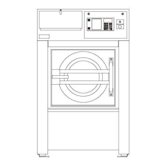
3.5. DIMENSIONS AND CONNECTIONS OF THE MACHINE 33/40/55 kg 80/100/125 lbs 22 kg / 50 lbs - „5 soaphoppers“ 22 kg / 50 lbs - „3 soaphoppers“ Fig. 3.5. INSTALLATION AND MAINTENANCE MANUAL PUBLICATION DATE 03/02 504 766... - Page 14 1. Front panel with operating elements 11. Plug of hole for external dosing hose 2. Electric switchboard cover 12. Name plate 3. Tub ventilation 13. Steam inlet 4. Lubrication 14. External protective clamp 5. Bushing of external dosing pumps electric connection 15.
-
Page 15: Installation
4. INSTALLATION 4.1. HANDLING, TRANSPORT AND STORAGE TRANSPORT AND STORAGE WARNING ! FORKS OF HIGH LIFTING TRUCK MUST HAVE SUFFICIENT LENGTH (SEE FIG. 4.1.A). Use a lift truck or a manual skid cart for handling with the machine in transporting package. –... -
Page 16: Space Requirements
4.2. SPACE REQUIREMENTS REQUIRED MACHINE WORKING CONDITIONS: See chapter „3. TECHNICAL SPECIFICATION“. The machine may not be installed within the reach of directly spraying water. Do not install the machine where it will be exposed to weather condition and excessive humidity. When steamed up due to temperature changing, water must not run over the machine walls and covers, nor to cover the floor under and around it. - Page 17 22 kg / 50 lbs 33 kg / 80 lbs 40 kg /100 lbs 55 kg / 125 lbs BOLT M10 x 160 mm M16 x 160 mm TIGHTENING MOMENT 49 Nm / 36 lbf.ft 210 Nm / 155 lbf.ft Tab.4.3.B Fig.4.3.A Distances between washing machines, walls and between other machines and optional design of the waste channel...
-
Page 18: Connections
22 kg 33 kg 40 kg 55 kg 22 kg 33 kg 40 kg 55 kg 50 lbs 80 lbs 100 lbs 125 lbs 50 lbs 80 lbs 100 lbs 125 lbs 774 mm 970 mm 1070mm 1250 mm 200 mm 300 mm 300 mm 300 mm... - Page 19 Inlet valves 1“ (machine 22 kg / 50 lbs capacity: 3/4“) for cold and hot water are delivered with the machine. For these valves use inlet pressure hoses with gaskets. Mount shut - off valves 1“ (machine 22 kg / 50 lbs capacity: 3/4“) to the water supply pipes, it will make the maintenance and cleaning of filters delivered with a machine easy.
- Page 20 ELECTRICAL CONNECTION The machine has been designed for connecting to the electrical network according the specification of your order. Before connection check the voltage values and the frequency stated in the machine label (fig.3.5, pos.12), if they correspond to your power network. The way of the connection is described in fig. 4.4.A. If the machine is not equipped with a main switch then supply disconnecting devices need to be provided in the installation for all electrical supplies connected to the machine, in accordance with EN 60204-1 standard, point 5.3.
- Page 21 PROTECTION WITH EARTH LEAKAGE TRIPS To increase the safety of the operating personnel and / or servicemen during the maintenance work and operation with electric devices it is recommended to mount in front of the supply cable in the laundry switchboard an earth leakage trip according to fig.
- Page 22 CONNECTING POINT The cable can be attached to the machine from a cable channel (from below). If the cable is attached from above, it is recommended to make a sag on the cable in front of the entry into the cable bushing (fig.4.4.C, pos.4).
- Page 23 CONNECTION TO LIQUID SOAP SUPPLY SYSTEM It is possible to connect external liquid soap supply system to the machine. Connect the hoses of liquid soap supplies on inlets of dosing pumps. Connect outlets on vertical inlets of external liquid soap mixer (fig.4.4.E, pos.2).
-
Page 24: Putting The Machine Into Service
and pass it in the appropriate opening in the machine. Connect these signal terminals like the manufacturer of the liquid soap system requires. The liquid soap system may draw maximum 0,1A out the control circuit of the washer-extractor. WATER RECYCLED DRAINAGE CONNECTION Valid only for machines equipped with recycled drainage by the manufacturer or for machines after modification. -
Page 25: Maintenance
5. MAINTENANCE WARNING ! ALWAYS FOLLOW SAFETY INSTRUCTIONS! DO NOT BYPASS ANY SAFETY DEVICES OR THEIR PARTS. ANY INTERFERENCE TO THE MACHINE FUNCTIONS AND CONSTRUCTION ARE PROHIBITED! USE THE PROPER CHEMICAL AGENTS WHICH AVOID CALCIUM SEDIMENTS ON HEATING ELEMENTS AND OTHER MACHINE PARTS. DISCUSS THIS ISSUE WITH YOUR SUPPLIER OF WASHING PRODUCTS. THE MANUFACTURER OF THE MACHINE IS NOT RESPONSIBLE FOR THE DAMAGE OF HEATING ELEMENTS AND OTHER MACHINE PARTS DUE TO CALCIUM SEDIMENTS. -
Page 26: Safety Vibration Switch
BEFORE REMOVING TOP OR BACK PANEL OF THE MACHINE, SWITCH POWER OFF AND WAIT FOR AT LEAST 10 MINUTES. BEFORE STARTING INSPECTION OF FREQUENCY INVERTER, CHECK FOR RESIDUAL VOLTAGE ACROSS MAIN CIRCUIT TERMINALS + AND -. THIS VOLTAGE MUST BE BELOW 30VDC BEFORE YOU CAN ACCESS THE INVERTER FOR INSPECTION. 3. -
Page 27: Tightening Moments
Side view Front view 1. Front face of the drum 4. Switchboard bottom 7. Vibration switch holder 2. Limiter 5. Vibration switch 3. Rubber bushing 6. Adjusting nut Fig.5.6. 5.7. TIGHTENING MOMENTS WARNING ! REGULARLY, ONCE IN THREE MONTHS OR EVERY 500 WORKING HOURS (WHICH EVER COMES FIRST) INSPECT THE TIGHTNESS OF THE BOLTS ! If anyone of the bolts has been damaged, exchange it with the bolt of the same strength value marked on its head. -
Page 28: Lubrication
MARKING OF THE BOLTS Bolts of hub flange Bolts fixing the rear wall of external drum to the inner drum covering over a tyre Bolts fixing the plate of motors to the outer face Bolts fixing the external drum to the front face Bolts fixing the support and damper holders to the rear wall of outer drum Bolts fixing the plate of motors to the damper holders Housing fixing the drum pulley to the shaft... -
Page 29: Driving Mechanism
Every time you use a grease gun especially for greasing bearings and seals, do it slowly - not faster than 5 strokes in 1 minute. The grease gun can create a high pressure which would cause the seal deformation and consequent leakage. Never operate the grease gun faster even if the grease contain air gaps. Overlubrication can cause the same damage as an insufficient lubrication. -
Page 30: Water And Steam Filters
BELT REPLACEMENT NEVER USE A CROWBAR TO TAKE OFF THE BELTS OVER THE PULLEY GROOVES. Loosen the bolts of tightening pulley on the drum rear wall and the adjusting screw for taking the belts off. TWO - MOTOR VERSION: Belts between motor for washing and motor for extracting are to be removed after loosing the bolts that fasten the motor for extracting and after loosing the tightening bolts. - Page 31 ADJUSTING ON THE SIDE OF THE DOOR HANDLE ONLY FOR MACHINE 33/40/55 kg 80/100/125 lbs 1. Unscrew the bolt (fig. 5.11.B, detail „B“, pos. 1) securing the casing of the door handle (2). 2. Unscrew the casing (2) from the door bearer (3) always by a whole turn that the groove in the casing thread (2) appears bellow the securing bolt (1).
-
Page 32: Spring Unit
If the thrust adjusting has not been sufficient, exchange the door seal. 5.12. SPRING UNIT Spring units (fig.5.12., pos.1) are to be adjusted in the case that you found out the suspended machine part is not in a horizontal position (without linen and water) or after the spring unit has been replaced. WARNING ! MAIN SWITCH MUST BE OFF! The spring unit adjusting is achieved by turning the nuts (2) with the same number of turns always simultaneously... -
Page 33: Values Of Fuses
Fig.5.13. Overcurrent relay 5.14. VALUES OF FUSES Values of fuses you can find on electrical scheme delivered with machine. Marking Destined for: FU1, FU2 transformer - primary winding control circuits clutch of 2-motor version pumps external dosing Tab.5.14. 5.15. EARTH LEAKAGE TRIPS If the laundry is equipped with the earth leakage trip in the inlet circuit of the electric switchboard it is necessary to test it regularly. -
Page 34: Trouble Shooting Aids
6. TROUBLE SHOOTING AIDS 6.1. DOOR BLOCKING DESCRIPTION OF DOOR LOCK FUNCTION The door lock has been designed as a compact unit. Its function is to secure the door against opening during the washing cycle. Unlocking after a cycle completion will be made by: a signal from the programmer (microprocessor version) a manual pressing of the lock push button (card version) The lock has been blocked also during the failure situations e.g. -
Page 35: Too Long Filling Time
Front view: machine 22 kg / 50 lbs Top view: machines 33/40/55 kg - 80/100/125 lbs Fig.6.1 6.2. TOO LONG FILLING TIME Low water pressure: -more machines have been filling up in the same time. The inlet valve filter clogged: WARNING ! STOP THE HOT WATER INLET TO THE MACHINE AND WAIT FOR COMPONENTS TO COOL DOWN! shut the main water inlet, take off the inlet valve filters, clean and put them back. -
Page 36: Too Long Drainage Time
6.4. TOO LONG DRAINAGE TIME Clogged drainage: -clean the outlet. Defected drainage valve: -clean the drainage valve or exchange it. Too small waste sump dimensions: -check the waste sump diameters and enlarge it accordingly. 6.5. PROGRAMMER PROBLEMS See the chapter „Troubleshooting“ in the programming manual according to your machine type: „Programming manual - Electronic programmer“... -
Page 37: List Of Recommended Spare Parts
7. LIST OF RECOMMENDED SPARE PARTS Find more detailed information in the spare parts catalogue for individual machines at your dealer. PRI 340 055 051 Drain valve 3“ 101 344 2-way inlet valve 3/4“ 101 345 3-way inlet valve 3/4“ FOR MACHINES 22 kg / 50 lbs CAPACITY PRI 340 200 056 1-way valve 3/4“... - Page 38 FOR MACHINES WITH ELECTRIC HEATING PRI 342 000 032 Heating element 6000W 220V PRI 342 000 031 Heating element 4000W 220V PRI 345 001 019 Contactor LC1 D4011 M7 PRI 345 006 011 Contactor LC1 D1801 M7 PRI 345 002 019 Contactor LC1 D3201 M7 FOR MACHINES WITH ELECTRONIC PROGRAMMER, MCB EC, MCB FC PRI 401 020 021...
-
Page 39: Putting The Machine Out Of Service
8. PUTTING THE MACHINE OUT OF SERVICE If the machine is out of service, possibly replaced, follow the instructions. 8.1. DISCONNECTING THE MACHINE 1. Switch off the external electric power inlet to the machine. 2. Turn off the main switch on the machine rear. 3. -
Page 40: Serial Number
IMPORTANT ! MACHINE TYPE: PROGRAMMER: -ELECTRONIC TIMER MCB EC -ELECTRONIC TIMER MCB FC -ELECTRONIC TIMER MCG FC -CARD PROGRAMMER K24 INSTALLATION DATE: INSTALLATION CARRIED OUT BY: SERIAL NUMBER: ELECTRICAL DETAILS: .....VOLT....PHASE....HZ NOTE: ANY CONTACTS WITH YOUR DEALER REGARDING MACHINE SAFETY, OR SPARE PARTS, MUST INCLUDE THE ABOVE IDENTIFICATION.
Need help?
Do you have a question about the F 22-55 and is the answer not in the manual?
Questions and answers