Table of Contents
Advertisement
Quick Links
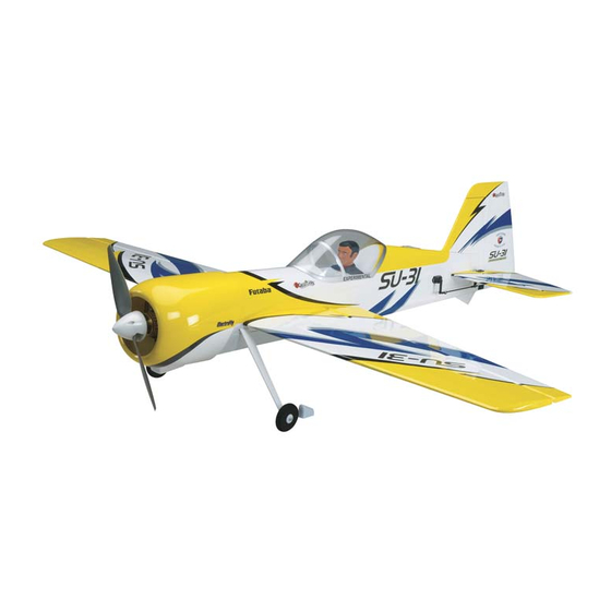
Wingspan: 41 in [1040mm]
Wing Area: 343 in
[22.1dm
]
2
2
Weight: 27.5 – 31 oz [780 – 880g]
Wing Loading: 11.5 – 13 oz/ft
2
Length: 38 in [965mm]
Radio: 4 + channel transmitter, 4 micro servos
Great Planes
Model Manufacturing Co. guarantees this kit to be
®
free from defects in both material and workmanship at the date
of purchase. This warranty does not cover any component parts
damaged by use or modification. In no case shall Great Planes'
liability exceed the original cost of the purchased kit. Further,
Great Planes reserves the right to change or modify this warranty
without notice.
In that Great Planes has no control over the final assembly or
material used for final assembly, no liability shall be assumed nor
accepted for any damage resulting from the use by the user of
the final user-assembled product. By the act of using the user-
assembled product, the user accepts all resulting liability.
If the buyer is not prepared to accept the liability associated
with the use of this product, the buyer is advised to return
this kit immediately in new and unused condition to the place
of purchase.
READ THROUGH THIS MANUAL BEFORE STARTING CONSTRUCTION. IT CONTAINS IMPORTANT
INSTRUCTIONS AND WARNINGS CONCERNING THE ASSEMBLY AND USE OF THIS MODEL.
Entire Contents © Copyright 2009
INSTRUCTION MANUAL
[35 – 40g/dm
]
2
Motor:
RimFire
.10 (35-30 -1250) out-runner brushless motor
™
ESC:
SS-35 35A brushless ESC
Battery: 3-cell 1250 to 2100mAh LiPo battery and
LiPo compatible charger
WARRANTY
To make a warranty claim send the defective part or item to Hobby
Services at the address below:
Include a letter stating your name, return shipping address, as
much contact information as possible (daytime telephone number,
fax number, e-mail address), a detailed description of the problem
and a photocopy of the purchase receipt. Upon receipt of the
package the problem will be evaluated as quickly as possible.
airsupport@greatplanes.com
Hobby Services
3002 N. Apollo Dr., Suite 1
Champaign, IL 61822 USA
Champaign, Illinois
(217) 398-8970, Ext 5
GPMA1547MNL V2.0
Advertisement
Table of Contents

Related Manuals for GREAT PLANES SU-31


Summary of Contents for GREAT PLANES SU-31
-
Page 1: Instruction Manual
READ THROUGH THIS MANUAL BEFORE STARTING CONSTRUCTION. IT CONTAINS IMPORTANT INSTRUCTIONS AND WARNINGS CONCERNING THE ASSEMBLY AND USE OF THIS MODEL. Champaign, Illinois (217) 398-8970, Ext 5 airsupport@greatplanes.com Entire Contents © Copyright 2009 GPMA1547MNL V2.0... -
Page 2: Table Of Contents
& OTHERS..FOLLOW THESE IMPORTANT SAFETY PRECAUTIONS INTROdUCTION 1. Your Sukhoi SU-31 EP ARF should not be considered a toy, but rather a sophisticated, working model that functions very much like a full-size airplane. Because of its performance Congratulations on your purchase of the Great Planes Sukhoi... -
Page 3: Decisions You Must Make
SU-31 EP ARF that may require planning or decision making before starting to build. Order numbers are provided in parentheses. The Sukhoi SU-31 EP ARF has been tested with 11.1V LiPo packs ranging from 1250mAh to 2100mAh. Order numbers Radio Equipment are provided for packs of this size. -
Page 4: Required Adhesive & Building Supplies
This is the list of adhesive and building supplies required • The stabilizer and wing incidences and motor thrust to finish the Sukhoi SU-31 EP ARF. Order numbers are angles have been factory-built into this model. However, provided in parentheses. -
Page 5: Kit Inspection
Product Support. When reporting defective or missing parts, use the part names exactly as they are written in the Kit Contents list. Great Planes Product Support: 3002 N. Apollo Drive, Suite 1 Champaign, IL 61822 Telephone: (217) 398-8970, ext. 5 Fax: (217) 398-7721 E-mail: airsupport@greatplanes.com kIT CONTENTS Kit Contents Cowl Tail Skid Fuselage Vertical Fin & Rudder... -
Page 6: Preparations
ASSEMBLE THE WINg PANELS 1. The aileron hinges for the SU-31 have been preinstalled. Please check them to be certain they are properly glued. If any of them are loose simply add a few drops of thin CA glue to the top and bottom of the hinge. - Page 7 transmitter. Test fit the double-sided servo arms parallel to the aileron hinge line. Decide which way fits best (closest to parallel) and cut off the arm that isn’t used. The remaining arm should point toward the wing tip. Be sure to make a left and right servo arm.
-
Page 8: Install The Wing Panels
9. Fit the clevises on the aileron pushrods into the outer 3. Slide the carbon wing tube into the wing tube channel holes of the aileron control horns and servo arms as shown. in the fuselage and center its position. (You may need to temporarily remove the servo arms from the servos.) With the servo arms parallel to the hinge lines and the ailerons in the neutral positions, center the length... -
Page 9: Assemble The Tail Section
ASSEMBLE THE TAIL SECTION 1. Trim the covering from the horizontal stabilizer slot in the fuselage. 4. Position the horizontal stabilizer into the stab saddle, centering it left and right and making it square to the wings. Stand back several feet behind the model and view it from the rear. - Page 10 with alcohol. Prepare the elevators by inserting a CA hinge into each hinge slot. Use T-pins to keep the hinges centered. Put a light coating of epoxy onto the ends of the elevator joiner wire. Install the elevators onto the joiner wire while fitting the CA hinges into their mating slots in the horizontal stabilizer.
-
Page 11: Install The Tail Servos & Pushrods
1. Trim the covering from the elevator and rudder servo bays on both sides of the fuselage as shown. Note: Please pay close attention to the location of the servo mounting holes in the preceding pictures. There are several lightening holes in this area of the airframe that might be mistaken for servo mounting holes. -
Page 12: Install The Landing Gear
INSTALL THE LANdINg gEAR 3. Attach an adjustable clevis to the outer holes of the servo arm and rudder control horn. Attach the arm to the servo with the servo arm screw. Install a 6-3/4" [170mm] pushrod into the clevises, center the control surface, and 1. -
Page 13: Mount The Motor, Esc & Receiver
4. Attach the landing gear to the fuselage using four 3 x 8mm 6. Trim the covering from the tail skid slot at the aft end machine screws, four 3mm washers, and threadlocking of the fuselage. Glue the tail skid into the slot using medium compound. - Page 14 2. Test fit the motor mount box together. The pieces are 5. Connect the motor leads on the ESC to the motor. This labeled and the motor mount is correspondingly marked. is a good time to confirm that the motor will rotate the correct When the motor mount box is correctly assembled it should direction (use your radio system to test the motor operation).
- Page 15 you balance the model, the exact position of the battery pack will be determined. When you know where the pack will need to be to balanced mark its position onto the battery tray. 8. Cut a small amount of the hook side of the non-adhesive back, hook and loop material.
-
Page 16: Install The Cowl, Canopy & Spinner
INSTALL THE COWL, CANOPY & SPINNER 1. Prepare the inside of the cowl by lightly scuffing it with 220-grit sandpaper. When satisfied, clean the inside with alcohol. 2. Glue the four plywood magnet back pieces to the cowl ring. Note: Pay attention to the position of the cowl magnet mounting holes in the photograph. -
Page 17: Apply The Decals
correct polarity facing out! The magnets in the fuselage must be attracted to the magnets in the cowl ring. Let the CA cure without accelerator. 7. Reattach the cowl to the fuselage. Install the propeller, prop washer, and prop nut onto the prop shaft. Install the spinner cone using the included spinner screws. -
Page 18: Get The Model Ready To Fly
gET THE MOdEL REAdY TO FLY Set the Control Throws Check the Control directions 1. Turn on the transmitter and receiver and center the trims. If necessary, remove the servo arms from the servos and reposition them so they are centered. Reinstall the screws that hold on the servo arms. -
Page 19: Balance The Model (C.g.)
If, after you have become accustomed to the way the Sukhoi SU-31 EP ARF flies, you would like to change 2. With all parts of the model installed (ready to fly) and the throws to suit your taste, that is fine. -
Page 20: Charge The Batteries
hand signals to show you what is happening. If the control Charge the Batteries surfaces do not respond correctly, do not fly! Find and correct the problem first. Look for loose servo connections or broken wires, corroded wires on old servo connectors, Follow the battery charging instructions that came with your poor solder joints in your battery pack or a defective cell, or a radio control system to charge the batteries. -
Page 21: Ama Safety Code (Excerpts)
9) Under no circumstances may a pilot or other person AMA SAFETY COdE (excerpts) touch a powered model in flight; nor should any part of the model other than the landing gear, intentionally touch the ground, except while landing. Read and abide by the following excerpts from the Academy of Model Aeronautics Safety Code. -
Page 22: Flying
CAUTION (THIS APPLIES TO ALL R/C AIRPLANES): If, Take it easy with the Sukhoi SU-31 EP ARF for the first while flying, you notice an alarming or unusual sound such few flights, gradually getting acquainted with it as you gain as a low-pitched “buzz,”... -
Page 23: 3D Flying
Have a ball! But always stay in control out, add power to pull the model around. Many models will and fly in a safe manner. require some rudder correction (usually right rudder) during this maneuver. Some planes will require aileron correction to gOOd LUCk ANd gREAT FLYINg! keep the wings level. - Page 24 but make your adjustments smooth. Some right aileron may change from up elevator to down elevator when inverted. If you be needed to keep the model from torque rolling. Use the are comfortable with four point rolls and slow rolls, inputting rudder rudder and elevator to keep the nose pointing straight up.
- Page 25 TECHNICAL NOTICE In the “ASSEMBLE THE WING PANELS” section, starting In the “MOUNT THE MOTOR, ESC & RECEIVER” section, on page 7, the steps are incorrectly numbered, however, starting on page 14, the steps are incorrectly numbered, all steps are included and should be followed in the however, all steps are included and should be followed order that they appear.
Need help?
Do you have a question about the SU-31 and is the answer not in the manual?
Questions and answers