Table of Contents
Advertisement
Quick Links
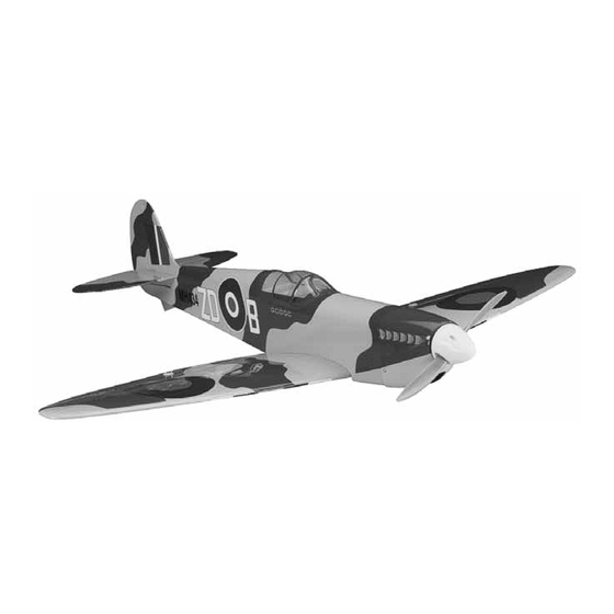
Wingspan: 39 in [990mm]
Wing Area: 272 in
2
[17.5dm
2
]
Weight: 40 – 48 oz [1130 – 1360g]
Wing Loading: 21 – 25 oz/ft
2
Length: 35.5 in [895mm]
Radio: 4-channel minimum w/4 to 5 micro servos and standard
size receiver
Engine: .25 cu in [4cc] two-stroke, 35-30-1450kV RimFire
out-runner motor
Great Planes
®
Model Manufacturing Co. guarantees this kit to be free from defects in both material and workmanship at the date of
purchase. This warranty does not cover any component parts damaged by use or modification. In no case shall Great Planes' liability
exceed the original cost of the purchased kit. Further, Great Planes reserves the right to change or modify this warranty without notice.
In that Great Planes has no control over the final assembly or material used for final assembly, no liability shall be assumed nor
accepted for any damage resulting from the use by the user of the final user-assembled product. By the act of using the user-assembled
product, the user accepts all resulting liability.
If the buyer is not prepared to accept the liability associated with the use of this product, the buyer is advised to return this
kit immediately in new and unused condition to the place of purchase.
To make a warranty claim send the defective part or item to Hobby Services at the address below:
Include a letter stating your name, return shipping address, as much contact information as possible (daytime telephone number, fax
number, e-mail address), a detailed description of the problem and a photocopy of the purchase receipt. Upon receipt of the package
the problem will be evaluated as quickly as possible.
READ THROUGH THIS MANUAL BEFORE STARTING
CONSTRUCTION. IT CONTAINS IMPORTANT INSTRUCTIONS
AND WARNINGS CONCERNING THE ASSEMBLY AND USE
OF THIS MODEL.
Entire Contents © Copyright 2007
INSTRUCTION MANUAL
[65 – 78g/dm
2
]
™
WARRANTY
Hobby Services
3002 N. Apollo Dr. Suite 1
Champaign IL 61822 USA
Champaign, Illinois
(217) 398-8970, Ext 5
airsupport@greatplanes.com
GPMZ1478 for GPMA1478 V1.0
Advertisement
Table of Contents

Related Manuals for GREAT PLANES SPITFIRE


Summary of Contents for GREAT PLANES SPITFIRE
-
Page 1: Instruction Manual
Further, Great Planes reserves the right to change or modify this warranty without notice. In that Great Planes has no control over the final assembly or material used for final assembly, no liability shall be assumed nor accepted for any damage resulting from the use by the user of the final user-assembled product. -
Page 2: Table Of Contents
ADDITIONAL ITEMS REQUIRED........4 For the latest technical updates or manual corrections to the Required Hardware & Accessories ......4 Combat Spitfire ARF visit the Great Planes web site at Adhesives & Building Supplies........4 www.greatplanes.com. Open the “Airplanes” link, then select Optional Supplies & Tools ...........4 the Combat Spitfire ARF. -
Page 3: Safety Precautions
1. Your Combat Spitfire ARF should not be considered a toy, but rather a sophisticated, working model that functions very much like a full-size airplane. Because of its performance... -
Page 4: Batteries & Charger
Propeller ❏ Pro 6-minute epoxy (GPMR6045) ❏ Epoxy brushes 6, (GPMR8060) ❏ If using the O.S. .25 FX glow engine or the Great Planes Mixing sticks (GPMR8055) ❏ 35-30-1450kV RimFire out-runner motor, we suggest using Mixing cups (GPMR8056) ❏ a 9" x 6" propeller. -
Page 5: Building Stand
® Building Stand ORDERING REPLACEMENT PARTS Replacement parts for the Great Planes Combat Spitfire ARF are available using the order numbers in the Replacement Parts List that follows. The fastest, most economical service can be provided by your hobby dealer or mail-order company. -
Page 6: Common Abbreviations
Replacement Parts List METRIC CONVERSIONS GPMA2821 ....Wing Set GPMA2822 ....Fuse Kit GPMA2823 ....Tail Set 1" = 25.4mm (conversion factor) GPMA2824 ....Cowl 1/64" .4mm 3/4" 19.0mm GPMA2825 ....Canopy GPMA2826 ....Landing Gear 1/32" .8mm 1" 25.4mm 1/16" 1.6mm 2" 50.8mm GPMA2827 ....Engine Mount GPMA2828 ....Decal Sheet 3/32"... -
Page 7: Kit Inspection
If any parts are missing or are not of acceptable quality, or if you need assistance with assembly, contact Product Support. When reporting defective or missing parts, use the part names exactly as they are written in the Kit Contents list. Great Planes Product Support: 3002 N Apollo Drive, Suite 1 Champaign, IL 61822 Telephone: (217) 398-8970, ext. -
Page 8: Preparations
If you plan to install the optional landing gear (sport flying), install the servos on the bottom of the wings. If you plan to use the Combat Spitfire ARF for combat flying, you may choose not to install the optional landing gear. In this case, install the servos into the top of the wing panels to protect the servos during belly landings. - Page 9 ❏ ❏ ❏ 2. Attach a 9" [230mm] servo extension to each aileron 4. Install the rubber grommets and eyelets that were servo. Secure the connection with tape or heat-shrink tubing included with the servo. Mount the servo in the servo bay (not included).
- Page 10 ❏ 10. Locate a 2mm x 120mm pushrod wire threaded on one ❏ 8. Place a control horn onto each aileron in line with the outer end. Screw a nylon clevis and a silicone clevis retainer onto the hole of the servo arm. We used a ruler as a straightedge. threaded end of the wire 20 full turns.
-
Page 11: Join The Wing
Join the Wing ❏ 4. Trim the covering that overlaps onto the root ribs of each wing panel. Mix approximately 1/2 oz [15cc] of 30- minute epoxy. Apply a liberal amount of epoxy into the wing joiner pocket of each wing, the root rib of each wing and the joiner. -
Page 12: Build The Fuselage
❏ 7.Trim the covering just inside your lines.Wipe away the lines with alcohol and glue the wing bolt plate to the wing. Continue the wing bolt holes through the wing bolt plate with a 5/32" [4mm] drill bit. A wood backer piece while drilling will help ensure clean-edged holes in the backplate. - Page 13 ❏ 4. Cut the covering away 1/16" [1.6mm] inside the lines you drew. ❏ 7. Fit the vertical fin into the fuse and trace around it onto the fin. Remove the fin and cut the covering away slightly beneath the lines you drew (leave the covering on the TE of the fin in place).
-
Page 14: Install The Elevator & Rudder Pushrods & Servos
Install the Elevator & Rudder Pushrods & Servos ❏ 3. With the other 19-3/4" [502mm] pushrod, install a control horn on the right side of the rudder in the same manner. ❏ 1. Locate and remove the covering from the pushrod exits on both sides of the fuse beneath the stab. -
Page 15: Glow Engine, Fuel Tank & Radio Installation
If you wish to use the fill line to drain the tank, attach a length of fuel tubing and an The Combat Spitfire ARF is designed to be flown with a .25 additional fuel clunk (not included) to the fill line inside the tank. - Page 16 ❏ 6. Attach a 6" [150mm] piece of fuel line to each of the metal tubes in the fuel tank. ❏ 8. Position the front of the engine drive washer 3-3/4" [95mm] from the firewall. Mark the location of the engine mount holes onto the engine mount halves using a Dead Center ™...
- Page 17 ❏ 10. Cut two 1-1/2" [38mm] pieces from the included 6mm x 6mm stick. Glue them to the fuse stringers flush with the fronts approximately 1-1/4" [32mm] behind the stick holding the fuel tank in place. ❏ 12. Fit the receiver tray onto the 6mm x 6mm sticks you glued in step 9.
-
Page 18: Out-Runner Motor, Battery & Radio Installation
the fuel tank! The bottom of the tank is 7/8" [22mm] above the top of the cooling hole cutout. To allow for some error, be sure that your hole is 5/8" [16mm] or closer to the cooling hole cutout. If in doubt, remove the tank before drilling your hole. Drill a hole through the second fuse former inline with the first (a long drill bit is helpful here). - Page 19 ❏ 5. Install the brushless motor onto the aluminum motor mount (included with the motor) using four 3mm x 8mm machine screws (included with the motor) and thread- locking compound. If you haven’t done so already, install the prop adapter using the hardware included with the motor. Glue the front adapter piece to the brushless motor mount box as shown.
- Page 20 ❏ 11. Cut a piece of 1/4" [6mm] or 1/2" [13mm] foam rubber (not included) to fit your receiver. Hook one of the included rubber bands onto the tab on the brushless radio tray and feed the other end above the tray and out of the throttle servo bay.
- Page 21 D. When satisfied, slide a piece of heat-shrink tubing over the adapter up to the base of the male bullet connector. If the Great Planes 4mm male to 3.5mm female bullet Use a heat gun or micro torch to shrink the tubing onto the connector adapters are not available, or you would like to adapter.
-
Page 22: Finish The Model
FINISH THE MODEL Install the Cowl The cowl installation is shown on the brushless motor power system. Installing the cowl over a glow engine is the same. However, in addition to cutting a cooling hole for the engine head, you will also need to make a hole for glow plug access, a ❏... - Page 23 balancing purposes. After the plane is completely assembled, experiment with the position of the pack if possible when balancing the plane and mark the optimum position of the pack onto the battery tray for future reference. ❏ 2. If you have not done so already, connect the elevator and rudder servos to the receiver.
-
Page 24: Optional Landing Gear
The Combat Spitfire ARF includes optional landing gear for those modelers who choose to sport fly the model and would benefit from using landing gear. The included landing gear is recommended for paved runways only. -
Page 25: Apply The Decals
Adjust if necessary. Set the Control Throws Use a Great Planes AccuThrow (or a ruler) to accurately measure and set the control throw of each control surface as indicated in the chart that follows. If your radio does not have dual rates, we recommend setting the throws at the low rate setting. -
Page 26: Balance The Model (C.g.)
❏ 3. If the tail drops, the model is “tail heavy” and the the Combat Spitfire ARF flies, you would like to change battery pack and/or receiver must be shifted forward or the throws to suit your taste, that is fine. However, too weight must be added to the nose to balance. -
Page 27: Balance The Model Laterally
Fill out the identification tag on the decal We use a Top Flite Precision Magnetic Prop Balancer sheet and place it on or inside your model. (TOPQ5700) in the workshop and keep a Great Planes Fingertip Prop Balancer (GPMQ5000) in our flight box. Charge the Batteries... -
Page 28: Engine / Motor Safety Precautions
LITHIUM BATTERY HANDLING & USAGE ENGINE / MOTOR SAFETY PRECAUTIONS WARNING!! Read the entire instruction sheet included with your battery. Failure to follow all instructions could cause permanent damage to the battery and its surroundings, and Failure to follow these safety precautions may result cause bodily harm! in severe injury to yourself and others. -
Page 29: Check List
2. Be certain the battery and receiver are securely mounted in the fuse. Simply stuffing them into place with foam rubber is not sufficient. The Combat Spitfire ARF is a great-flying model that flies ❏ 3. Extend your receiver antenna. -
Page 30: Takeoff
Take it easy with the Combat Spitfire ARF for the first few CAUTION (THIS APPLIES TO ALL R/C AIRPLANES): If, flights, gradually getting acquainted with it as you gain while flying, you notice an alarming or unusual sound confidence. Adjust the trims to maintain straight and level such as a low-pitched “buzz,”... - Page 31 R/C combat flying requires a special breed of pilot…and a durability and smooth operation, plus a low crankcase special type of aircraft. Great Planes’ 1/12 scale fighters profile that allows for a proportionately taller, semi-squared meet the criteria perfectly: quick and easy to assemble, very head to increase cooling fin area.
- Page 32 BUILDING NOTES Kit Purchased Date: _______________________ Date Construction Finished: _________________ Where Purchased:_________________________ Finished Weight: __________________________ Date Construction Started: __________________ Date of First Flight: ________________________ FLIGHT LOG...
Need help?
Do you have a question about the SPITFIRE and is the answer not in the manual?
Questions and answers