Table of Contents
Advertisement
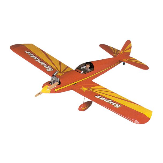
Wing Span - 55.5 in
Wing Area - 550 sq in
Weight - 5.5 lbs
Wing Loading - 23 oz/sq ft
Fuse Length - 46-3/4 in
Great Planes
Model Manufacturing Co. guarantees this kit to be free from defects in both material and workmanship at the date of
®
purchase. This warranty does not cover any component parts damaged by use or modification. In no case shall Great Planes' liability
exceed the original cost of the purchased kit. Further, Great Planes reserves the right to change or modify this warranty without
notice.
In that Great Planes has no control over the final assembly or material used for final assembly, no liability shall be assumed nor
accepted for any damage resulting from the use by the user of the final user-assembled product. By the act of using the user-
assembled product, the user accepts all resulting liability.
If the buyer is not prepared to accept the liability associated with the use of this product, the buyer is advised to return this
kit immediately in new and unused condition to the place of purchase.
While this kit has been flight tested to exceed normal use, if the plane will be used for extremely high stress flying, the modeler is
responsible for taking steps to reinforce the high stress points.
READ THROUGH THIS MANUAL BEFORE
STARTING CONSTRUCTION. IT CONTAINS
IMPORTANT WARNINGS AND INSTRUCTIONS
CONCERNING THE ASSEMBLY AND USE OF
THIS MODEL.
© Copyright 2000
INSTRUCTION MANUAL
WARRANTY
P.O. Box 788
Urbana, IL 61803
A.R.F.
Almost Ready to Fly
(217) 398-8970
GPMZ0218 for GPMA1040 V1.0
Advertisement
Table of Contents

Subscribe to Our Youtube Channel
Related Manuals for GREAT PLANES Super Sportster 40


Summary of Contents for GREAT PLANES Super Sportster 40
-
Page 1: Instruction Manual
In that Great Planes has no control over the final assembly or material used for final assembly, no liability shall be assumed nor accepted for any damage resulting from the use by the user of the final user-assembled product. By the act of using the user- assembled product, the user accepts all resulting liability. -
Page 2: Table Of Contents
Fuel Tank Installation ..........10 Engine Installation............11 Landing Gear Installation...........12 Tail Gear Installation ..........13 The Great Planes Super Sportster ARF is an easy to fly Radio Installation ............14 sport scale airplane that closely resembles the full-size Battery & Receiver Installation ........16 Super Sportster both in appearance and performance. -
Page 3: Decisions You Must Make
❏ Epoxy Brushes (GPMR8060) and are listed for your ordering convenience. GPM is the ❏ Epoxy Mixing Sticks (GPMR8055, Qty. 50) Great Planes brand, TOP is the Top Flite brand, and HCA ® ❏ is the Hobbico brand. -
Page 4: General Inspection
General Inspection Building Notes Several times during construction we refer to the “top” or Eliminate any wrinkles you find in the covering by shrinking “bottom” of the model or a part of the model. It is understood them away with a low temperature setting on a heat gun, then apply pressure to the area with a covering iron and a that the “top”... -
Page 5: Parts List
Parts List Pushrods Hardware Key# Description Replacement Parts Fuselage If needed, replacement parts for Super Sportster ARF are Left Wing Panel w/Aileron available through your hobby supplier. Right Wing Panel w/Aileron Cowl Wing Set ............GPMA2125 Adjustable Engine Mount Fuselage Kit ..........GPMA2126 Fuel Tank Tail Fin Set ............GPMA2127 Canopy... -
Page 6: Begin Construction
BEGIN CONSTRUCTION Wing Assembly ❏ 1. Draw a centerline on both sides of the wing joiner ❏ 3. Test fit the wing panels together with the joiner in as shown. position. They must fit flush against each other without any gaps. - Page 7 ❏ 6. Assemble the two wing halves with the tightest seam possible. No gaps should be showing between the two ❏ halves. Use a paper towel dampened with alcohol to wipe 8. Prepare the aileron servo with grommets and bushings away any more epoxy that oozes out of the wing Use as shown in the sketch.
-
Page 8: Wing Installation
Wing Installation ❏ 12. Attach the clevises to the aileron control horns. Press the forks of the clevises together until the pin snaps into the opposite fork. Slide the clevis retainer into position over ❏ 1. Locate the holes for the wing bolts and remove the covering the clevis forks. - Page 9 ❏ ❏ 2. Insert the stabilizer into the horizontal stabilizer slot so 5. Remove the stabilizer and draw two additional lines on it is centered in the fuselage (A). Place the wing onto the the top and two on the bottom, 1/16" [1.5mm] inside the fuselage and secure it with the 1/4-20 x 2"...
-
Page 10: Fuel Tank Installation
If you are using a hobby knife, do not cut the wood under the covering! This will seriously weaken the stabilizer and could easily cause the stabilizer to break in flight. If the fin breaks, the plane has a very good chance of crashing. -
Page 11: Engine Installation
Engine Installation ❏ 3. Install the spinner backplate, propeller, propeller washer and the propeller nut onto the engine. Turn the propeller counterclockwise until it is against the smallest pins on the backplate. Keep the propeller horizontal when the engine is against its compression (the point at which you feel resistance when you turn the crankshaft counterclockwise). -
Page 12: Landing Gear Installation
Landing Gear Installation ❏ ❏ 1. On the bottom of the wing, there are two channels for ❏ the main landing gear. Locate these channels by running 6. Remove the propeller, spinner backplate and muffler your finger over the covering on the bottom of the wing. Use from the engine. -
Page 13: Tail Gear Installation
❏ ❏ 10. File a flat spot along the bottom of the axle. This provides a better area for the set screw to bite and helps keep the wheel in place. Install the wheel pants by placing these items onto the landing gear wire in this order: Wheel pant, 5/32"... -
Page 14: Radio Installation
tail gear assembly to the plate using two #2 x 1/2" sheet metal screws. ❏ 3. Slide the tail gear actuator onto the tail gear wire. Mark the location of the actuator on the rudder and remove the covering inside those marks. Use 6-minute epoxy to attach the actuator to the rudder. - Page 15 ❏ 8. Center the elevator and elevator servo and mark the ❏ 5. Make a 90º bend in the pushrod on your mark, then pushrod where it crosses the servo arm. Enlarge the servo insert it through the enlarged hole in the servo arm. Secure horn hole with a 5/64"...
-
Page 16: Battery & Receiver Installation
Apply a small amount of thin CA onto the threads of the Great Planes model shop. Drill a 1/4" [6mm] hole through pushrod connector. The throw will be correct when the the fuse side in the proximity of the receiver. -
Page 17: Balance Your Model
1. The balance point (C.G.) is located 3-5/16" [84mm] back the opposite, lighter wing tip. from the leading edge of the wing against the fuselage. Balance your Super Sportster using a Great Planes C.G. Note: An airplane that has been laterally balanced will track Machine Airplane Balancer (GPMR2400) for the most ™... -
Page 18: Preparing To Fly Your Super Sportster Arf
We use a Top Flite Precision Magnetic Prop Balancer ™ exhaust gives off a great deal of deadly carbon monoxide. (#TOPQ5700) in the workshop and keep a Great Planes Therefore do not run the engine in a closed room or garage. Fingertip Balancer (#GPMQ5000) in our flight box. -
Page 19: Ama Safety Code (Excerpt)
Make all engine adjustments from behind the rotating FLYING YOUR SUPER propeller. SPORTSTER ARF The engine gets hot! Do not touch it during or after operation. Make sure fuel lines are in good condition so fuel will not leak onto a hot engine, causing a fire. The Super Sportster ARF is a great flying sport airplane that To stop the engine, cut off the fuel supply by closing off the flies smoothly and predictably, yet is highly maneuverable. -
Page 20: Flight Log
BUILDING NOTES Kit Purchased Date: _______________________ Date Construction Finished: _________________ Where Purchased:_________________________ Finished Weight: __________________________ Date Construction Started: __________________ Date of First Flight: ________________________ FLIGHT LOG...
Need help?
Do you have a question about the Super Sportster 40 and is the answer not in the manual?
Questions and answers