Advertisement
Quick Links
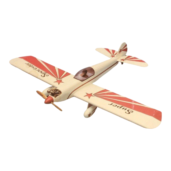
The Super Sportster was designed for the sport flier The Sportster is fast, stable and aerobatic It has good looks, good performance and
stability at low speeds For the creative builders it can be detailed to resemble a war bird, Formula 1 racer or a CAP 21 type aerobatic ship Materials
are included for both trike gear and conventional gear (taildragger) to help you create your own Sportster
The parts are machine cut and sanded for accurate fit Some parts are razor cut in the 20 size for accuracy Should you notice a difference in
size between plans and parts, it is usually because paper plans change size with moisture Most of the parts are self aligning and do not require
building over the plans except where specified in the instructions
Different types of glues may be used such as epoxy, Cyanoacrylate or aliphatic (white) resin Be careful when using any kind of glue Make sure
you have enough ventilation CA glues (instant) are especially harmful if not used correctly
We suggest that you build on a flat surface to insure a straight wing and fuselage When you build over the plans, cover them with waxed paper
so the wood parts are not glued to the plans'
The following tools will be helpful when you build and X-Acto knife, razor plane, saw sanding block, flat building board T Pins hinge slotting
kit, drill and drill bits, tap and tap holder, covering iron and heat gun, Dremel tool and cutter tor wire and router bits, soldering iron, screw drivers, needle
nose pliers, files, clamps and a good square or right triangle
We recommend a plastic heat shrink covering such as Super Monokote to keep your Sportster light Follow the manufacturer's instructions
concerning the use of this covering material
Please read through this step by step instruction book before you start building so you will get an overall idea of the construction steps and avoid
mistakes Since these instructions do pertain to the 20, 40 and 60 size Sportsters, refer to the plan and parts list to help you identify the various parts
Any differences in the instructions for the various size models will be noted at the appropriate steps with a star (•*)
These instructions and plans were intended tor 2 cycle engine use However starting on page 26 of this booklet, you will find adaptation
instructions for the installation of 4-cycle engines
Please inspect all parts carefully before starting to build! If any parts are missing, broken or defective, or it you have any questions
about building or flying this airplane, please call us at (217) 398-8970 and we'll be glad to help. It you are calling tor replacement parts,
please look up the part numbers and the kit identification number (stamped on the end of the carton) and have them ready.
Great Planes Model Manufacturing Co., Inc. guarantees this kit to be free of defects in both material and workman-
ship at the date of purchase This warranty does not cover any component parts damaged by use or modification In no
case shall Great Planes' liability exceed the original cost of the purchased kit Further, Great Planes reserves the right to
change or modify this warranty without notice.
In that Great Planes has no control over the final assembly or material used for final assembly, no liability shall be
assumed nor accepted for any damage resulting from the use by the user of the final user-assembled product.
By the act of using the user-assembled product the user accepts all resulting liability.
If the buyer is not prepared to accept the liability associated with the use of this product, he Is advised
to immediately return this kit in new and unused condition to the place of purchase.
READ THROUGH THIS INSTRUCTION BOOK FIRST. IT CONTAINS
IMPORTANT INSTRUCTIONS AND WARNINGS CONCERNING THE
ASSEMBLY AND USE OF THIS MODEL.
(SEE WARNING ON BACK COVER)
Sportster
Engine
Wing Span
Wing Area
Length
Weight
MATERIALS NEEDED TO COMPLETE THIS KIT:
4 channel radio
Engine
Fiberglass cloth/resins
Engine mounting bolts
Propeller
WARRANTY
40
20
.19-.25
.35..45
48"
56"
400 sq. in.
550 sq. in.
43"
39-1/2"
3-1/2-4 lbs.
5 lbs.
Wheel collars
Wheels
Epoxy
Fuel tank
Spinner
POBOX788 URBANA, ILLINOIS 61801 (217)398-8970
66
.45-.61
61-1/2"
675 sq.in.
48"
6-7-1/2 lbs.
Covering
Instant glue
White glue
Advertisement

Related Manuals for GREAT PLANES Super Sportster 20


Summary of Contents for GREAT PLANES Super Sportster 20
- Page 1 In that Great Planes has no control over the final assembly or material used for final assembly, no liability shall be assumed nor accepted for any damage resulting from the use by the user of the final user-assembled product.
- Page 2 BUILDING THE TAIL SECTION 1. D PREPARE THE FIN AND RUDDER Prepare the forward and rear fin sections by sand- ing if necessary for a good fit. Working over the plans, butt glue the fin section together. After the glue is dry, sand both sides of the fin.
- Page 3 5. D GROOVE OUT THE ELEVATORS FOR JOINER WIRE CLEARANCE Cut a groove in the elevator leading edge inboard (inside) of the hole so when the joiner wire is installed it will be flush with the leading edge of the elevator. Groove both elevator halves.
- Page 4 2. D GLUE THE 1/16" PLYWOOD LANDING GEAR SUP- PORTS TO THE RIBS Start on the right wing panel by gluing the 1/16 ply brace on the left side of rib 2 and on the right side of rib 3. (For the left panel the brace glues on the right side of rib 2 and on the left side of rib 3.) When the glue is dry sand the braces to the rib contour.
- Page 5 6. D ADD THE TOP SPAR, TOP LEADING EDGE SHEET- ING AND TOP TRAILING EDGE SHEETING Glue the top spar in place. Glue the top leading edge sheeting between the leading edge and the dotted line on the top spar shown on the plans. Align the top trail- ing edge sheeting even with the back of the trailing edge and glue it in place.
- Page 6 10. D TRIAL FIT THE MAIN GEAR WIRE INTO THE GEAR BLOCK Remove the landing gear block from the wing and temporarily install the landing gear wire. The torque arm should slide into the hole you drilled earlier with the long arm resting in the groove in the long block.
- Page 7 14. D ADD ALL THE BOTTOM SHEETING TO THE WING PANEL Add the bottom leading edge sheeting, the trailing edge sheeting and the center section sheeting. Relieve (cut away) the leading edge sheeting for landing gear block clearance. (Relieve the center section sheeting for tricycle gear.) Add the bottom cap strips.
-
Page 8: Joining The Wing Panels
19. D PREPARE THE CENTER TRAILING EDGE PIECES With the top of the wing panels up, draw a center- line down the trailing edge of each wing panel. Prepare the grooved center trailing edge pieces by notching them for the servo arm torque rod clearance 3/8" or so in from the wing center. - Page 9 3. D JOIN THE WING PANELS Join the wing panels upside down. Refer to the di- hedral detail on the plans. Align at the leading and trailing edges. Use a straight edge to make sure the wing is straight. Block up the wing 3/4" at the center for the 20 size, 1"...
- Page 10 BUILDING THE FUSELAGE 1. D PREPARE THE FUSELAGE SIDES Mark the inside of the fuselage sides "right" and "left". Relieve the wing saddle area as necessary to match the plans. STOP! If you plan to install a 4-cycle engine read and follow the instructions on installation of 4-cycle engines at the end of this instruction book starting on page 26.
- Page 11 5. D GLUE THE DOUBLERS TO THE FUSELAGE SIDES Using bulkhead #1 as a spacer, install the 1/8" balsa doublers (1/16" for the 20 size) cross-grain on the inside of the fuselage sides. Custom cut pieces from the stock pro- vided.
- Page 12 9. D SAND FUSELAGE TAIL; GLUE BULKHEADS #2 AND #3 TO THE RIGHT FUSELAGE SIDE Slightly relieve the inside edges of the fuse sides at the tail for a better glue joint. Notch a hole for the throttle linkage in the side of bulkhead #2 first before gluing it to the fuselage side.
- Page 13 13. D GLUE IN BULKHEAD #1 Realign the fuselage over the plans and glue the fuse sides to bulkhead #1. Make sure the top of the bulkhead is flat on the building board and that the front of the bulkhead is facing forward. 14.
- Page 14 17. D GLUE THE FUSELAGE TO THE DECK BASE Glue the fuselage sides/bulkhead assembly to the deck base/former assembly. Fuselage sides are glued to the sides of the deck base and the sides of the formers. The deck base should glue to the rear of bulkhead #3. DO NOT GLUE THE FUSELAGE TOGETHER AT THE TAIL UNTIL YOU READ THE NEXT STEP! 18.
- Page 15 21, D GLUE THE CHIN BLOCK TO THE FUSELAGE With the fuselage still at 90 degrees to the board and over the plans, align the chin block to the back of bulk- head #2 and glue the chin block to the fuselage. *0n the Sportster 20 make the rear end of the block even with the wing saddle openings in the fuselage sides.
- Page 16 25. D GLUE ON FORMERS 1A and 2A; SAND THEM SO HOOD TOP FITS; TRIAL FIT THE FUEL TANK Glue formers 1A and 2A to the tops of bulkheads 1 and 2. When the glue is dry sand the tops of these formers to a slight angle so the hood top will mate squarely when glued.
- Page 17 29. D INSTALL AND GLUE ON THE HOOD SIDE PIECES Sand the bottom of the side pieces so they will mate squarely with the fuselage sides. Glue the side pieces from the front of former 3A/3B to beyond former 1A in the following manner.
- Page 18 33. D GLUE ON THE 1/4" x 1/4" BALSA TOP STRINGER Cut to length and glue the 1/4" x 1/4" balsa stringer in place between formers 3A/3B and 6A/6B. 34, D ADD FORMERS 4A AND 5A Locate the positions of formers 4A and 5A by placing a straight edge along the top stringer.
- Page 19 37. D CUT AWAY AREAS FOR ENGINE CLEARANCE; DRILL HOLES IN MOUNT FOR ENGINE; TEMPO- RARILY MOUNT ENGINE TO FUSE Temporarily install your mount and engine. Relieve the engine compartment so the engine rests flat on the engine mount. Check for binding of the throttle arm.
- Page 20 41. D ALIGN THE STABILIZER TO THE FUSELAGE First align the fuselage to a flat work surface. The fuselage reference line (the line along the top of the fuselage side - see step 9 on page 12) should be parallel to the work surface.
-
Page 21: Final Assembly
FINAL ASSEMBLY 1. D ALIGN THE FUSELAGE TO THE WORK SURFACE AND THE WING TO THE FUSELAGE Align the fuselage upside down to the work surface using the line along the top of the fuselage side as the reference line. This line should be parallel to the flat work surface. - Page 22 3. D SAND THE WING FAIRINGS TO SHAPE Prepare to install the wing fairings by drawing lines on the bottom of the wing even with the fuselage sides. Cut the fairings to width. Sand to shape by placing sand- paper on the wing and working the fairings back and forth. *The 60 size has three fairing blocks where the 40 size has only two.
- Page 23 7. D DRILL 1/4" DOWEL HOLES THROUGH THE DOWEL JIG HOLES INTO BULKHEAD #2; GLUE DOWELS INTO THE WING Use the holes in the dowel jig as a guide and drill 1/4" holes into bulkhead #2. Remove the dowel jig and now permanently install this jig with epoxy using the drilled holes to align the jig in the exact position.
- Page 24 11. D INSTALL RADIO COMPONENTS IN THE FUSE- LAGE Glue servo rails made from scrap plywood or hardwood into the radio compartment. Install the rudder, elevator and throttle servo directly to the hardwood rails or install the servo tray that comes with your radio.
- Page 25 fit before you glue the two halves together When the 18. D COVER THE MODEL halves are Joined, sand lightly along the Join line on the outside of the pant to get a smooth appearance Remove any equipment that will be in the way while you are covering.
- Page 26 25. D RANGE CHECK YOUR RADIO SYSTEM, WIRE CHECK CENTER GRAVITY, LANDING GEAR WHEEL PANT RECHECK ALL ALIGNMENTS WHEEL COLLARS Your model should balance at the point shown on the plan If it doesn't, move the battery #2 SCREW and/or receiver around until the model balances at BRASS PLATE the point shown If additional balance weight is needed, add lead weights to the nose or tail to get...
- Page 27 2-Cycle .40's and it produces comparable power and thrust. SUPER SPORTSTER 20: For this airplane a Saito .30 will give comparable power to a 2-Cycle but weighs more and is larger than a 2-Cycle. See page 33 for a drawing of the Saito .30 in a Sportster 20.
- Page 28 This distance is "B". Refer to the drawings and the chart on the next page. We are measuring this distance so we can determine how far back to move the firewall so the engine will fit into the nose of the model. Figure 1 2-CYCLE ENGINE GREAT PLANES MOUNT...
- Page 29 Figure 2 HAYES MOUNT Now let's figure out how far back to move the firewall from the normal 2-cycle position. We have already figured out for you the "A" distance of the Sportster 20 (3-5/16"), the Sportster 40 (3-3/4") and the Sportster 60 (4-1/8").
- Page 30 Basically all we've done here is to measure how long your new mount and engine is, allow for some spinner back plate space and subtract the distance shown on the plan (A) from the distance you measured (B). The result gives you the distance you have to move the firewall back. (See Figure 3 and 4 also.) Let's do an example to show this.
- Page 31 Step 36 Check for adequate width clearance for your engine. If your 4 cycle and mount is over 2" wide for the Sportster 20, 2-1/4" for the 40 and over 2-5/8" for the 60 size, you'll need to relieve the 3/8" or 1/2" balsa nose blocks and the 3/8"...
-
Page 32: General Information
GENERAL INFORMATION Center of Gravity: A nose heavy airplane can be a problem! Make sure you check the CG location during construction with the radio components installed. You may need to put the radio as far back in the compart- ment as possible. - Page 38 SUPER SPORTSTER 20 PARTS LIST PART# QTY DESCRIPTION PART# QTY DESCRIPTION BAL046 Balsa 1/4 x 1/4 x 36 Fuselage Brace SUB PACK - HARDWARE SS20M01 BAL047 Balsa 1/8 x 1/4 x 36 Former Stock GLPT001 Fiberglass Tape 1 x 8...
- Page 39 SUPER SPORTSTER 40 PARTS LIST PART# QTY DESCRIPTION PART# QTY DESCRIPTION BAL009 Balsa 3/32x1 M X 36 Cap Strip SS40F31 SUB PACK - FUSE STRINGER BAL015 Balsa 3/32 x 3 x 7 Center Sheet SS40F11 Balsa 1 / 4 x 1 / 4 x 1 6 Stringer BAL019 Balsa 1/4 Triangle Fuselage Brace SS40F12...
- Page 40 SUPER SPORTSTER 60 PARTS LIST PART# QTY DESCRIPTION PART# QTY DESCRIPTION BAL009 Balsa 3/32 x 1/4 x 36 Cap Strip BAL015 Balsa 3/32 x 3 x 7 Center Sheet SS60A04 SUB PACK - RIBS AND FORMERS Balsa 1/4 Triangle Fuselage Brace Balsa 1/8 Former 3B, 4A, 5A, 6B (Die-Cut) BAL019 SS60F33...
- Page 41 Use trim MonoKote and these letters to create your trim scheme on your Sportster.
- Page 43 PUSHROD LINKAGES...
- Page 44 WARNING! THIS IS NOT A TOY! THIS IS NOT A BEGINNER'S AIRPLANE! This R/C kit and the model you will build is not a toy! It is capable of serious bodily harm and property damage. IT IS YOUR RESPONSIBILITY AND YOURS ALONE -- to build this kit cor- rectly, properly install all R/C components and flying gear (engine, tank, pushrods, etc.) and to test the model and fly it only with experienced, competent help, using common sense and in accordance with all safety standards as set down in the Academy of Model Aeronautics Safety...
Need help?
Do you have a question about the Super Sportster 20 and is the answer not in the manual?
Questions and answers