Table of Contents
Advertisement
Quick Links
Download this manual
See also:
Instruction Manual
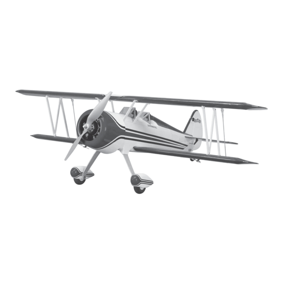
SPECIFICATIONS
Wingspan: 36 in [915 mm]
Wing Area: 365 in
Wing Loading: 14 −17 oz/ft
Length: 29.5 in [750 mm]
WARRANTY
Great Planes Model Manufacturing
be free from defects in both material and workmanship at the
date of purchase. This warranty does not cover any component
parts damaged by use or modification. In no case shall Great
Planes' liability exceed the original cost of the purchased kit.
Further, Great Planes reserves the right to change or modify this
warranty without notice.
In that Great Planes has no control over the final assembly or
material used for final assembly, no liability shall be assumed nor
accepted for any damage resulting from the use by the user of
the final user-assembled product. By the act of using the
user-assembled product, the user accepts all resulting liability.
If the buyer is not prepared to accept the liability associated
with the use of this product, the buyer is advised to return
READ THROUGH THIS MANUAL BEFORE STARTING CONSTRUCTION. IT CONTAINS IMPORTANT
INSTRUCTIONS AND WARNINGS CONCERNING THE ASSEMBLY AND USE OF THIS MODEL.
®
Entire Contents © 2011 Hobbico,
Inc. All rights reserved.
2
2
[23.5 dm
]
2
2
[43 − 52 g /dm
]
®
Co. guarantees this kit to
INSTRUCTION MANUAL
Weight: 2.25 − 2.75 lb
[1020 −1250 g]
Radio: Minimum 4-channel
with 4 micro servos
this kit immediately in new and unused condition to the
place of purchase.
To make a warranty claim send the defective part or item to
Hobby Services at the address below:
Include a letter stating your name, return shipping address, as
much contact information as possible (daytime telephone
number, fax number, e-mail address), a detailed description of
the problem and a photocopy of the purchase receipt. Upon
receipt of the package the problem will be evaluated as quickly
as possible.
Power
Rimfire
™
.10 [35 − 30 − 1250],
System:
SS35, 2200 mAh 3S LiPo,
APC 10 × 7E, 35A ESC
Hobby Services
3002 N. Apollo Dr. Suite 1
Champaign IL 61822 USA
Champaign, Illinois
(217) 398-8970, Ext 5
airsupport@greatplanes.com
®
GPMA1150 Mnl
Advertisement
Table of Contents

Related Manuals for GREAT PLANES Super Stearman


Summary of Contents for GREAT PLANES Super Stearman
-
Page 1: Instruction Manual
3002 N. Apollo Dr. Suite 1 Champaign IL 61822 USA In that Great Planes has no control over the final assembly or material used for final assembly, no liability shall be assumed nor Include a letter stating your name, return shipping address, as... -
Page 2: Table Of Contents
Follow These Important Safety Precautions site at www.greatplanes.com. Open the “Airplanes” link, then 1. Your Super Stearman EP should not be considered a toy, select the Great Planes Super Stearman EP ARF. If there is but rather a sophisticated, working model that functions very new technical information or changes to this model a “tech... -
Page 3: Decisions You Must Make
DECISIONS YOU MUST MAKE Sheet Metal Screws are designated by a number and a This is a partial list of items required to fi nish the Great Planes length. For example #6 × 3/4" [19mm]. Super Stearman EP that may require planning or decision This is a number six screw making before starting to build. -
Page 4: Kit Inspection
● When you see the term test fi t in the instructions, it means To locate a hobby dealer, visit the Great Planes web site at www.greatplanes.com. Select “Where to Buy” in the menu that you should fi rst position the part on the assembly... -
Page 5: Kit Contents
KIT CONTENTS 1. Fuselage 8. Landing Gear 15. “N” Struts 2. Cowl 9. Wheel Pants 16. Bottom Wing & Ailerons 3. Fin & Rudder 10. Wheels 17. Top Wing & Ailerons 4. Tail Cone 11. Axles 18. Cabanes 5. Tail Wheel Assembly 12. -
Page 6: Preparations
PREPARATIONS Tighten the Covering Refer to the separate instruction sheet titled How To Tighten Covering On ARF Models. Follow the instructions to tighten the covering. If you prefer to get started on assembly right away, the tightening process could be done later (but it is usually easiest to do while the model is still in separate pieces). - Page 7 ❏ ❏ 7. Install the z-bend end of a 5/64" x 6" [2mm x 152mm] aileron pushrod wire into the hole you drilled in the nylon servo arm. ❏ ❏ 8. Locate a black control horn. Important! The hardware includes two different style horns. Be sure you use the horn pictured here.
-
Page 8: Install The Stab, Elevators, Fin And Rudder
pushrod wire and then insert the screw-lock connector into the aileron control horn. Secure the connector with the black nylon retainer. Center the aileron servo and the aileron. Apply a drop of thread locker to the 2-56 x 3/16" [4.8mm] set screw and then tighten the screw against the pushrod wire. - Page 9 ❏ 2. Temporarily bolt the wing to the fuselage with two 4-40 x 1" [25mm] bolts and #4 fl at washers. ❏ 6. Temporarily install the rudder into the opening in the stab. ❏ 7. Measure the distance from the tips of the stab to the tips of the wing.
- Page 10 ❏ 9, Look at both elevator halves. You will see a slot in the left elevator. When installing the elevators in the next step, be sure the elevator half with the slot is installed on the left half of the stab and the slot is on the bottom of the elevator. ❏...
- Page 11 with the fi t, apply a couple of drops of oil to the wire where it passes through the bearing. This will prevent any glue from getting into the nylon bearing. Apply a small amount of 30-minute epoxy to both sides of the nylon bearing and into the slot in the fuselage.
-
Page 12: Install The Landing Gear, Wheels
❏ ❏ 18. Included in the kit are two 15-3/4" [400mm] pushrod 20. Repeat this for the rudder pushrod and control horn. wires with a Z-bend on one end. The wires most likely have some glue residue on them from the masking tape that held them together. - Page 13 ❏ 4. Install an axle into each of the landing gear legs and secure them with the 3/16" [5mm] axle lock nuts. ❏ 5. Slide two 3/16" [5mm] washers onto each axle followed ❏ by the wheel. Install a 6-32 x 1/8" [3mm] set screw into the 2.
-
Page 14: Install The Motor Speed Control
Install the Motor Speed Control, Receiver & Servos If you have the bottom wing installed, remove it. This will make the following installation easier. ❏ 2. Install the speed control onto the Velcro ® you installed inside the fuselage. The motor leads should be fed through the front of the fuselage. - Page 15 ❏ 7. Install a longer servo arm on the rudder servo. The arm must be long enough so that you can install the screw lock ❏ 4. Two lengths of Velcro ® are included with the kit to secure connector into a hole approximately 1/2" [13mm] from the the battery.
-
Page 16: Install The Cabanes, Wings And Struts
Install Cabanes, Wings & Struts ❏ 10. Plug the servo and ESC leads into the appropriate channels of the receiver and then install the servo to the ❏ tray. Route the antenna wire following the instructions with 1. Locate the four wing cabanes and lay them out as shown the receiver. - Page 17 ❏ 5, Bolt the bottom wing to the fuselage with two 4-40 x 1" wing bolts and #4 fl at washers. ❏ 3. These pictures show how the cabanes look when they have been properly installed. ❏ 6. Apply RC Z 56 glue to the bottom edge of the wing fairing. Position the fairing on the wing.
-
Page 18: Final Assembly
❏ 11. Locate one of the 5/64" x 6" [2mm x 150mm] wires with a Z-bend on one end and threads on the other. Thread a ❏ 8. Each of the tabs is lettered “A”, “B” and “C”. Test fi t two nylon clevis onto the threaded end of the wire approximately “A”... -
Page 19: Get The Model Ready To Fly
❏ submersing them in soap & water allows accurate positioning 4. If the prop is on the airplane remove it, the nut and and reduces air bubbles underneath. washer. Arm the speed control and slowly start the motor. Be sure the motor is turning in a counter clockwise direction as ❏... -
Page 20: Balance The Model (C.g.)
1/4" 1/2" use Great Planes “stick-on” lead (GPMQ4485). To fi nd out [6 mm] 6° [13mm] 12° how much weight is required, place incrementally increasing amounts of weight on the top of the fuselage over the location Right &... -
Page 21: Balance Propellers
We use a Top Flite Precision Magnetic Prop Balancer 5) I will not fl y my model unless it is identifi ed with my name (TOPQ5700) in the workshop and keep a Great Planes and address or AMA number, on or in the model. Note: This Fingertip Prop Balancer (GPMQ5000) in our fl... -
Page 22: Check List
CHECK LIST FLYING The Great Planes Super Stearman EP is a great-fl ying model During the last few moments of preparation your mind that fl ies smoothly and predictably. The Super Stearman EP may be elsewhere anticipating the excitement of the fi rst does not, however, possess the self-recovery characteristics of fl... -
Page 23: Flight
maintain your glide path and airspeed. If you are going to Flight overshoot, smoothly advance the throttle (always ready on the right rudder to counteract torque) and climb out to make For reassurance and to keep an eye on other traffi c, it is a another attempt. - Page 24 ® Entire Contents © 2011 Hobbico, Inc. All rights reserved. GPMA1150 Mnl...
Need help?
Do you have a question about the Super Stearman and is the answer not in the manual?
Questions and answers