Table of Contents
Advertisement
Quick Links
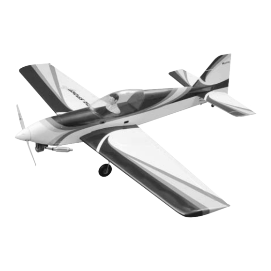
Wingspan: 58-1/2 in [1485mm]
Wing Area: 595 sq in [38.4 dm
Weight: 5.3-5.7 lbs [2400 – 2600g]
Wing Loading: 20.5-22.3 oz/sq ft [62.5 – 67.7 g/dm
Length: 46 in [1170mm]
Radio: 4-Channel with 5 servos
Engine: .40 to .52 cu in [6.5 – 8.5cc] two-stroke, .52 to
.70 cu in [8.5 – 11.5cc] four-stroke
Great Planes
®
Model Manufacturing Co. guarantees this kit to be free from defects in both material and workmanship at the date of
purchase. This warranty does not cover any component parts damaged by use or modification. In no case shall Great Planes' liability
exceed the original cost of the purchased kit. Further, Great Planes reserves the right to change or modify this warranty without
notice.
In that Great Planes has no control over the final assembly or material used for final assembly, no liability shall be assumed nor
accepted for any damage resulting from the use by the user of the final user-assembled product. By the act of using the user-assembled
product, the user accepts all resulting liability.
If the buyer is not prepared to accept the liability associated with the use of this product, the buyer is advised to return this
kit immediately in new and unused condition to the place of purchase.
READ THROUGH THIS MANUAL BEFORE STARTING
CONSTRUCTION.
INSTRUCTIONS AND WARNINGS CONCERNING
THE ASSEMBLY AND USE OF THIS MODEL.
USB4P03 for GPMA0390 V:1.0 Printed in USA
INSTRUCTION MANUAL
2
]
IT
CONTAINS
2
]
WARRANTY
IMPORTANT
1610 Interstate Drive Champaign, IL 61822
(217) 398-8970, Ext. 2
airsupport@greatplanes.com
Entire Contents © Copyright 2002
™
Advertisement
Table of Contents

Related Manuals for GREAT PLANES Ultra Sport 40 Plus


Summary of Contents for GREAT PLANES Ultra Sport 40 Plus
-
Page 1: Instruction Manual
In that Great Planes has no control over the final assembly or material used for final assembly, no liability shall be assumed nor accepted for any damage resulting from the use by the user of the final user-assembled product. By the act of using the user-assembled product, the user accepts all resulting liability. -
Page 2: Table Of Contents
3D throws will make hovering maneuvers easy. BUILDING INSTRUCTIONS............9 BUILD THE TAIL SURFACES ............9 The Great Planes Ultra Sport 40 Plus is a great sport Build the Stab & Elevator ............9 airplane that will do anything the pilot asks. -
Page 3: Decisions You Must Make
The recommended engine size range for the Great Planes airplane, please call us at (217) 398-8970, or e-mail us at Ultra Sport 40 Plus is a .40 to .52 cu in [6.5 – 8.5cc] two- productsupport@greatplanes.com . If you are contacting stroke, or .52 to .70 cu in [8.5 –... -
Page 4: Additional Items Required
It is also the etc.), this is the “short list” of the most important items most aerodynamic and the “coolest” by far. required to build the Great Planes Ultra Sport 40 Plus. We recommend Great Planes Pro ™... -
Page 5: Important Building Notes
• Whenever the term glue is written you should rely upon While building the Great Planes Ultra Sport 40 Plus, two your experience to decide what type of glue to use. When a 5-1/2" [140mm] Bar Sanders and two 11" [280mm] Bar... -
Page 6: Common Abbreviations
the parts from their die sheets, if they are difficult to remove, TYPES OF WOOD do not force them out. Instead, use a sharp #11 blade to carefully cut the part from the sheet, then lightly sand the edges to remove any slivers or irregularities. Save some of the larger scraps of wood. -
Page 7: Die Patterns
DIE PATTERNS... -
Page 8: Retract Wire Template
DIE PATTERNS RETRACT WIRE TEMPLATE... -
Page 9: Building Instructions
glue them in place with medium CA to form the stab inner BUILDING INSTRUCTIONS structure. 6. Locate the 1/8" x 1/8" x 30" [3.2mm x 3.2mm x 760mm] balsa sticks. Cut them to size as shown on the plans to BUILD THE TAIL SURFACES complete the stab’s inner structure. - Page 10 Repeat this procedure for the leading edge of the two elevators. A great tool for marking the center of the trailing edge is the Great Planes Precision 12. Sheet the top and bottom of the stab by applying Hinge Marking Tool (GPMR4005).
-
Page 11: Build The Fin & Rudder
CA into the holes. Build the Fin & Rudder We have simplified the task of cutting hinge slots with the introduction of the Great Planes Slot Machine . This ™ simple electric tool cuts a perfect width slot for use with 1. - Page 12 around it using the 1/8" x 1/2" x 30" [3.2mm x 13mm x 760mm] balsa sticks. Cut them to size as shown on the plan. 4. Cut the 1/8" x 1/4" x 30" [3.2mm x 6.4mm x 760mm] and the 1/8" x 1/8" x 30" [3.2mm x 3.2mm x 760mm] balsa sticks to size to form the rudder inner structure.
-
Page 13: Build The Wing
1/8" [3.2mm] wide from the bottom of the rudder up Failure to do so will result in a wing that is not straight. to the hole. Hint: A perfect tool for this is the Great Planes Groove Tube ™... - Page 14 7. Locate two 1/8" x 1/4" x 30" [3.2mm x 6.4mm x 760mm] hardwood wing spars. Insert them in place in the ribs as shown. You should now have the top and bottom wing spars inserted on the wing ribs as shown. Do not glue the spars in place yet.
- Page 15 13. Locate one die-cut 1/8" [3.2mm] lite-ply aileron servo tray (AST).The tray is not symmetrical because of the sweep of the main wing spar. Place the aileron servo tray against the wing main shear web (MSW) and the wing rib W4. The servo tray will only fit one way, so flip it if you need to.
- Page 16 19. Locate one 1/16" x 1/2" x 30" [1.6mm x 13mm x 22. Fixed Mains and Tailwheel. Locate one of the 760mm] balsa sub-leading edge. Glue it in place in front of 1/2" x 3/4" x 5-1/2" [13mm x 19mm x 140mm] hardwood all ribs with medium CA.
- Page 17 The strength of your landing gear depends on how well you glue these parts in place. Make sure W3-A, WL-A and W4-A are also glued well to the wing’s main shear web (MSW) and to the sub-leading edge doubler (SED). 27.
- Page 18 30. Flip the wing over again to work on the top side. 33. Once the glue has cured, flip the wing over and Locate a 1/16" x 3/4" x 30" [1.6mm x 19mm x 760mm] balsa add more glue if necessary to attach the sheeting to the ribs stick.
- Page 19 36. Cut the leftover sheeting from step 31 with the 38. Use the sketch in step 31 to prepare the sheeting grain into 3/8" [9.5mm] wide balsa strips. Use these strips to for the bottom wing surface. Glue the sheeting in place using make your cap strips.
- Page 20 sand the trailing edge sheeting flush with the wing trailing edge (TE). Sand the top and bottom of the wing smooth. 43. Use the same method described on step 14, page 41. Mark the trailing edge of the wing where the aileron 10 to draw a centerline on the wing trailing edge and aileron ends between W2 and W3.
- Page 21 47. Use a high speed rotary tool to drill a 1/2" [13mm] hole in the top sheeting of the center-section as shown above. The exact location of the hole is not important as long as it is behind the main wing spar. 45.
- Page 22 52. Fixed Mains and Tailwheel. Locate the Fixed Mains and Tailwheel landing gear cut-out template. Place it as shown on the bottom sheeting. Cut the sheeting as indicated by the template. 49. Retractable Mains/Fixed Tailwheel. Fit your retractable landing gear to the opening. Cut the sheeting as needed so that the gear is flush with the sheeting.
-
Page 23: Join The Wings
the excess glue and sand the edges smooth. Also, make a Join the Wings line at the center of the wing joiner. 3. Test fit the wing joiner into the wing joiner pocket between the main wing spars and shear webs. Note: The top of the wing joiner is marked with a “TOP.”... -
Page 24: Build The Fuselage
2.Position the fuselage plan flat on the building board. Cover the plan with Great Planes Plan Protector or waxed paper so glue will not adhere to it. 6. Drill a 1/4" [6.4mm] hole through DP where the holes on WDP are as shown above. - Page 25 side is what builds the engine right thrust so it is important to install the left and right side correctly. 6. Glue the right FSD on the assembled right forward fuselage side as shown with epoxy. The top and forward edge of the two parts must be aligned when glued.
- Page 26 11. Locate the die-cut 1/8" [3.2mm] lite-ply fuselage former F3 and the die-cut 3/32" [2.4mm] balsa fuselage formers F4, F5 and F6. Glue them in position on the fuselage top as indicated on the plans. Make sure that all formers are glued 90 degrees to the building board.
- Page 27 16. Make a mark on the tubes where they contact the fuselage formers and sides. Remove the tubes. Then roughen the tubes with sandpaper at the marks you have made. Reinstall the outer pushrod tubes back into the fuselage and glue them in place with thin CA. The tubes should extend about 2"...
- Page 28 22. Cut another piece of leftover balsa as shown in the above photo and glue it to the inside of the hatch cover to stiffen it up. This piece of balsa should extend from the line you just marked to the edge of the cover lip. Glue this in with CA.
- Page 29 26. Locate the two die-cut 1/8" [3.2mm] lite-ply formers F1-A. Glue them together with epoxy. Wipe away the excess epoxy with a paper towel dampened with alcohol. Sand the edges smooth after the glue has cured. 28. Locate and cut out the engine mount template on page 57 of this manual.
- Page 30 with thin CA. Note: If you will be installing a tricycle gear just under the throttle pushrod as shown above. Use epoxy with nose steering, you will need to repeat this procedure for to glue it in place. the steering pushrod on the other side of the fuselage. 33.
- Page 31 mark with CA. Also, glue F5-A in place. Both formers should be 90 degrees with the top of the fuselage. 36. Use the die-cut 1/16" [1.6mm] balsa aft template 39. Insert the cockpit floor in the space between F3-A (AT) to glue the die-cut 3/32" [2.4mm] balsa former F4-A at and F4-A.
- Page 32 1' [255mm] sections. Connect each one of the fuel tubes to the fuel tank and label them “vent,” “carburetor” and “fill.” Note that if you plan to use a Great Planes Easy Fueler Valve (GPMQ4160), you only need two lines, the carburetor and the vent line.
- Page 33 the bottom edge to the top of the fuselage side and the 3/16" [4.8mm] balsa stick. Tape the sheet in place while the glue cures. 47. Locate a 1/16" x 3" x 18" [1.6mm x 76mm x 457mm] balsa sheet. Use the preceding sketch to cut the sheeting for the forward sheeting.
-
Page 34: Radio And Engine Installation
50. Glue two pieces of 1/8" x 1/4" [3.2mm x 6.4mm] balsa 53. Fixed Mains and Tailwheel and Retractable stick on top of each other at the center of the top fuselage Mains/Fixed Tailwheel. Temporarily install the tail wheel as shown. assembly into the rudder and fit the rudder to the fin and fuse. - Page 35 2. Install the elevator, rudder and throttle servos as indicated on the plans with the hardware supplied by the manufacturer. Make sure you use thin CA in the servo screw holes in the balsa rails. 5. Center the servos and position the servo arms as shown in the photo.
-
Page 36: Engine Installation
(F1). Use FasLink. Cut the excess wire 1/16" [1.6mm] away from the some Great Planes Pro Threadlocker on the engine mount FasLink. bolts and tighten the SHCS. - Page 37 4-7/8" to 5" [124mm to 127mm] in front of the firewall (F1). Mark the position of the engine mounting holes onto the mount. A Great Planes Dead Center Hole Locator (GPMR8130) works great for this. Remove the engine from the mount.
-
Page 38: Mount The Wing To The Fuselage
SHCS will be installed. Remember, the steering arm is at a slight angle and so the flat spot will be, too. Use Great Planes Pro Threadlocker on the steering arm’s SHCS. - Page 39 mounting plate doubler (MPD). Glue the two parts together with 30-minute epoxy as shown on the plans. Then glue the assembly in position as shown in the image on the previous page. 4. Align the aft edge of the wing bolt plate (WBP) with the line on the wing (remember, you are working on the bottom of the wing).
- Page 40 1/4-20 tap. Enlarge the holes in the wing with a 1/4" [6.4mm] drill bit. Reinforce the area with thin CA. 7. Place a piece of waxed paper or Great Planes Plan Protector between the wing and the fuselage. Install the wing in place and tighten the wing bolts.
-
Page 41: Install The Landing Gear
12. Draw a line between the marks you made in step 9. Draw another mark 1/2" [13mm] away from the belly pan edges at the line. Use a high speed rotary tool to open up holes at the marks for the wing bolts. 15. - Page 42 3. Retractable Mains/Fixed Tailwheel. Install the retract servo in place with the hardware supplied by the manufacturer. Remove the servo’s output shaft. 1. Retractable Mains/Fixed Tailwheel. Cut out the root rib so that the retract servo fits between the wing dowels. Place the servo between the dowels as shown above.
- Page 43 Locate two 4-40 x 1/8" [3.2mm] SHCS and use them to hold the wire in place as shown. Apply some Great Planes Pro Threadlocker on the SHCS. Use the above images for reference.
- Page 44 6-32 x 1/4 [6.4mm] SHCS for both wheels. holes for the landing gear straps mounting holes. Wick thin File flat spots for the wheel collars. Use Great Planes Pro CA into the holes. Repeat this step for the other wing.
-
Page 45: Assemble The Cowl
adjusted later, when the cowl position has been fixed with ASSEMBLE THE COWL the cowl screws. 1. Locate the two cowl halves. Cut the two cowl halves at the cut marks with Hobbico’s Curved-Tip Canopy scissors (HCAR0667). 4. Position the spinner backplate against the engine’s drive washer. -
Page 46: Cover The Model With Monokote
1. NEVER CUT THE COVERING DIRECTLY ON THE SHEETING. The Ultra Sport 40 Plus depends on the sheeting for some of its strength. Modelers who cut through the covering tend to cut the sheeting and this will weaken the structure. -
Page 47: Covering Sequence
400-grit sandpaper. fuselage. Adjust the stab until both sides measure the same. Use Great Planes 1/8" [3.2mm] EZ-Mask Flexible Masking 2. If you covered the center-section of the stab, draw the Tape (GPMR1000) for masking sharp lines. A Top Flite Tack outline of the fuselage on the stab with a felt-tip marker. -
Page 48: Join The Control Surfaces
JOIN THE CONTROL SURFACES Now that the control surfaces are covered, you can permanently install the hinges into the control surfaces. 4. Add six drops of thin CA to the center of the hinges on both the top and bottom. The holes you drilled in the hinge slot will wick the CA into the entire hinge surface. -
Page 49: Finish The Cockpit
always use some kind of rubber padding to protect the Finish the Cockpit battery from vibration. 2. Wrap the receiver in 1/4" [6.4mm] R/C foam and install it in place as shown on the plans. Use a piece of scrap 1/4" x 1/2"... -
Page 50: Set The Control Throws
If, after you have become accustomed to the reverse the servos connected to those controls. Be certain way the Great Planes Ultra Sport 40 Plus flies, you would the control surfaces have remained centered. Adjust if like to change the throws to suit your taste, that is fine. -
Page 51: Balance The Model Laterally
the 1 oz. weight, or GPMQ4646 for the 2 oz. weight). If spinner weight is not practical or is not enough, use Great Planes (GPMQ4485) “stick-on” lead. A good place to add stick-on nose weight is to the firewall (F1) (don’t attach weight to the cowl–it is not intended to support weight). -
Page 52: Balance The Propellers
™ Keep your face and body as well as all spectators away from (TOPQ5700) in the workshop and keep a Great Planes the plane of rotation of the propeller as you start and run Fingertip Prop Balancer (GPMQ5000) in our flight box. -
Page 53: Ama Safety Code (Excerpt)
Be sure to check the items off as they are The Great Planes Ultra Sport 40 Plus is a great-flying model completed (that’s why it’s called a check list! ). -
Page 54: Fuel Mixture Adjustments
CAUTION (THIS APPLIES TO ALL R/C AIRPLANES): If, Take it easy with the Great Planes Ultra Sport 40 Plus for while flying, you notice any unusual sounds, such as a the first few flights, gradually getting acquainted with it as low-pitched “buzz,”... - Page 55 GOOD LUCK AND GREAT FLYING! Great Planes Extra 300S .40 Make a copy of the identification tag shown below and Ideal for MiniMAC, Great Planes’ sport-scale Extra 300S kit place it on or inside the model. requires no more experience, expense or assembly work than the average mid-size sport model.
- Page 56 Muffler and glow plug included. Two-year warranty. OSMG0872 Great Planes .40-Size Mechanical Retracts Simple, sensibly priced, low-profile Great Planes retracts offer a proven design and unique features. Mounting flanges on the nylon-reinforced composite housing conform to airfoil shapes, ensuring a neat, smooth appearance. A deployment angle of 88°...
-
Page 57: Fixed Taildragger Template
ENGINE MOUNT TEMPLATE... -
Page 59: Retract Template
Note: Make a copy of the Two View Drawing that appears on the back cover page before cutting out this template. -
Page 60: Two View Drawing
TWO VIEW DRAWING Use copies of this page to plan your trim scheme...
Need help?
Do you have a question about the Ultra Sport 40 Plus and is the answer not in the manual?
Questions and answers